The Hall sensor is designed to determine the spark torque in the vehicle's contactless ignition system (BCG).
Working principle of the Hall sensor
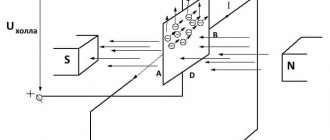
The principle of operation of the sensor is based on the Hall effect, when the magnetic field of a conductor changes when a special screen with slots passes through it.
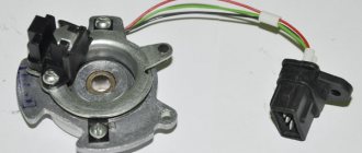
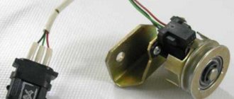
In practice, it looks like this: the Hall sensor of VAZ 2108, 2109, 21099 cars is installed on the distributor base plate and consists of two parts - a magnet and a Hall element with an amplifier. Voltage to the Hall sensor is supplied from the switch (pin 5) via the red current wire. The "ground" also comes from the switch: a black and white wire from pin 3. The magnet creates a magnetic field, the Hall element receives it, creates a voltage that amplifies the amplifier, and through a green pulse the voltage is applied to the switch. (conclusion 6).
To change the magnetic field, a shield with four slots is used, which rotates as the ignition distributor shaft (distributor) passes between the magnet and the receiving part of the Hall sensor. When the screen slot passes through the groove of the sensor, the magnetic field has a certain value, and as a result, the sensor supplies an electric current of a certain voltage (9-12 V) to the switch. When the shield tooth passes through the sensor groove, the magnetic field is shielded and does not enter the sensor receiver, and the voltage supplied to the switch drops (0-0.5 V).
As a result, the switch turns off the electric current supplied to the ignition coil, the magnetic field inside it is greatly compressed and, passing through the turns of the winding, creates an EMF of 22-25 kV (high voltage current). The current flows through the armored wires to the distributor and then to the spark plugs, creating a discharge that ignites the fuel mixture. The passage of each of the four screen teeth into the sensor groove corresponds to the compression stroke in one of the four engine cylinders.
Notes and additions
— The operating principle of many other automotive sensors is based on the Hall effect, for example, the injection speed sensor VAZ 21083, 21093, 21099.
More articles about car sensors VAZ 2108, 2109, 21099
The Hall sensor is one of the most important elements of the contactless ignition system for gasoline engines. The slightest malfunction of this part leads to serious malfunctions in the engine. Therefore, in order to avoid diagnostic errors, it is important to know how to check the Hall sensor and, if necessary, be able to replace it.
We have divided this material into two parts: theoretical (purpose, design and principle of operation of the Hall sensor) and practical - signs of malfunction, test methods and replacement methods.
At the end of the article, watch a video tutorial on how to replace the Hall sensor yourself.
And before checking the Hall sensor for faults, let's understand its purpose and operating principles.
What is a Hall sensor and how does it work
The Hall sensor (also known as a camshaft position sensor) is one of the main elements of the distributor (switch-distributor). It is located next to the distributor shaft, on which a magnetically conductive plate, similar to a crown, is attached. There are as many grooves in the plate as there are cylinders in the engine. There is also a permanent magnet inside the sensor.
The principle of operation of the Hall sensor is as follows: when the shaft rotates, metal blades alternately pass through a slot in the sensor. As a result, a pulse voltage is generated, which is supplied through a switch to the ignition coil and, converted into high voltage, is supplied to the spark plugs.
The Hall sensor has three outputs:
- you connect to the "mass"
- the second one is suitable for a plus with a voltage of about 6V,
- From the third output, the converted pulse signal is supplied to the switch.
Electrical diagram of VAZ 21083
1- block headlight; 2- electric motors for headlight cleaners; 3- fog lights; 4- engine compartment lamp switch; 5 - sound signal; 6- electric motor of the engine cooling system fan; 7- fan motor activation sensor; 8- front brake pad wear sensor; 9- generator; 10 - solenoid valve for turning on the headlight washers; 11- solenoid valve for turning on the rear window washer; 12- solenoid valve for turning on the windshield washer; 13- glass washer motor; 14- oil pressure warning lamp sensor; 15- oil level sensor; 16- washer fluid level sensor; 17 - fuel consumption sensor; 18- carburetor solenoid valve; 19- carburetor limit switch; 20- starter enable relay; 21- spark plugs; 22- ignition distributor sensor; 23 - vehicle speed sensor; 24- carburetor solenoid valve control unit; 25- diagnostic block; 26- ignition coil; 27- reverse light switch; 28 - coolant temperature indicator sensor; 29- starter; 30 - top dead center sensor of the 1st cylinder; 31- switch; 32- battery; 33- coolant level sensor; 34- relay for turning on fog lights; 35- brake fluid level sensor; 36- mounting block; 37-plug socket for a portable lamp; 38- door lock control unit; 39- engine compartment lamp; 40- electric motor for windshield wiper; 41- glove compartment lighting lamp; 42- heater fan electric motor; 43- additional resistor of the heater electric motor; 44- heater fan switch; 45- heater backlight lamp; 46- gearmotors for electric windows of the front doors; 47- gearmotors for blocking door locks; 48- ignition switch; 49- right door power window switch; 50- left door power window switch; 51- ignition relay; 52- steering column switch; 53- trip computer; 54- cigarette lighter; 55 - instrument lighting regulator; 56- parking brake warning lamp switch; 57- brake light switch; 58 - indicator lamp for turning on the heated rear window; 59- rear window heating switch; 60 - fog light switch; 61 - control lamp for turning on fog lights; 62 - indicator lamp for turning on the rear fog light; 63- rear fog light switch; 64- side direction indicators; 65 - lamp switch on the door pillars; 66- fog light circuit fuse; 67 - external lighting switch; 68 - instrument cluster VAZ 2108; 69- carburetor air damper warning lamp switch; 70- hazard switch; 71- lampshade; 72- connector for connecting to an individual lighting lamp; 73- rear lights; 74- license plate light; 75 - rear window wiper motor; 76 - rear window heating element; 77 - level indicator and fuel reserve sensor.
The numbering order of the plugs in the blocks is: A – mounting block, instrument cluster, steering column switch, ignition switch and windshield wiper; B – headlight and rear window cleaners; B – speed and fuel consumption sensor and in the ignition distributor; G – gear motors for power windows and gear motors for locking door locks.
Full size diagram:
Signs of a Hall sensor malfunction
Hall sensor malfunctions manifest themselves in different ways. Even an experienced technician will not always immediately determine the cause of an engine malfunction.
Here are some of the most common symptoms:
- The engine starts poorly or does not start at all.
- At idle, there are interruptions and jerks in the engine operation.
- The car may shake when driving at higher speeds.
- The power unit is blocked while driving.
If any of these signals appear, you must first check the functionality of the Hall sensor.
Also, other ignition system malfunctions found in cars should not be excluded from view.
Purpose of DC in the car ignition system
Having understood the principle of operation of the Hall element, let's consider how this sensor is used in the contactless ignition system of the VAZ line of cars. To do this, let's look at Figure 5.
Rice. 5. Principle of the SBZ device
Designations:
- A – sensor.
- B – magnet.
- C – plate made of magnetically conductive material (the number of protrusions corresponds to the number of cylinders).
The operating algorithm of such a scheme is as follows:
- When the chopper-distributor shaft rotates (moving synchronously with the crankshaft), one of the protrusions of the magnetically conductive plate takes a position between the sensor and the magnet.
- As a result of this action, the magnetic field strength changes, which causes the DC to operate. It sends an electrical impulse to the switch that controls the ignition coil.
- The voltage required to form a spark is generated in the Coil.
It would seem nothing complicated, but the spark must appear at a certain moment. If it forms earlier or later, it will cause a malfunction of the engine, even stopping it completely.
Manifestation of malfunction and possible causes
Irregularities in the operation of household farms can be detected by the following indirect signs:
- There is a sharp increase in fuel consumption. This is due to the fact that the fuel-air mixture is injected more than once during one crankshaft rotation cycle.
- Manifestation of unstable engine operation. The car may begin to “twitch” and a sharp deceleration occurs. In some cases, it is not possible to reach a speed of more than 50-60 km/h. The engine stalls during operation.
- Sometimes the failure of the sensor can lead to the transmission being locked, without the ability to shift it (in some models of imported cars). To correct the situation, a restart of the engine is required. In case of regular such cases, one can confidently state that the DP has failed.
- Often, a breakdown can manifest itself in the form of the disappearance of the ignition spark, which, accordingly, will make it impossible to start the engine.
- The self-diagnosis system may experience regular failures, for example, the check engine light will come on when it is idling, and the light will go out when the speed increases.
It is not at all necessary that the listed factors are caused by the failure of the DP. There is a high probability that the malfunction is caused by other reasons, namely:
- ingress of debris or other foreign objects onto the DP housing;
- the signal wire has broken;
- water has entered the DP connector;
- the signal wire is shorted to ground or the on-board network;
- the shielding sheath on the entire harness or individual wires is torn;
- damage to the wires supplying power to the DC;
- the polarity of the voltage supplied to the sensor is reversed;
- problems with the high-voltage circuit of the ignition system;
- problems with the control unit;
- the gap between the DC and the magnetic conductive plate is incorrectly set;
- Perhaps the reason lies in the high amplitude of the end runout of the camshaft gear.
How to check the Hall sensor
A simple way to check the camshaft position (Hall) sensor is shown in the following video.
There are several ways to check the operation of the Hall sensor. Each motorist will be able to choose the most suitable option for himself:
- Get a working sensor for testing from a neighbor or when the car is demolished and install it in the place of the original one. If the engine problems go away, you will need to purchase a new part.
- Using a tester, you can measure the voltage at the sensor output. In a working device, the voltage will vary from 0.4V to 11V.
- You can create a simulation of a Hall sensor. To do this, remove the three-pin block from the distributor. Then turn on the ignition and connect terminals 3 and 6 of the switch with a piece of wire. The appearance of a spark indicates a sensor failure.
If after inspection it is discovered that the Hall sensor is faulty, it must be replaced with a new one.
Car modifications
VAZ-2108 . The base model of the car, it was equipped with a 1.3-liter carburetor engine, was equipped with both a 4- and 5-speed gearbox.
VAZ-21081 . Modification of a car with a derated 1.1 liter engine and a 4-speed gearbox.
VAZ-21083 . Modification of a car with a 1.5 liter carburetor engine. This car was equipped with a 5-speed gearbox.
VAZ-21083-00 . A modification of the VAZ-21083 car as standard, an index of this length began to be assigned in 2001.
VAZ-21083-01 . Modification of the VAZ-21083 car in the “norm” configuration.
VAZ-21083-02 . Modification of the VAZ-21083 car in the “luxury” configuration.
VAZ-21083-20 . Modification of the VAZ-21083, but with an injection 1.5 liter engine. The car was equipped with a 5-speed gearbox.
VAZ-21083-21 . Like the previous model, but in the “norm” configuration.
VAZ-21083-22 . Modification of the VAZ-21083 car with an injection engine and a 5-speed gearbox in the “luxury” configuration.
VAZ-21083-37 . A sports model with a 1.5-liter fuel-injected engine and a 5-speed gearbox. Designed for participation in the NGS "Lada Cup"
VAZ-210834 "Tarzan" . A prototype of an all-wheel drive SUV, developed in 1998 based on model 21083. The car was made as follows: on the frame of the VAZ-21213 Niva, on which the suspension, steering, engine, gearbox and transfer case were already installed, the body from the VAZ-21083 was installed . The junctions between the frame and the body were covered with plastic covers that look like thresholds. The wheel arches were also enlarged, on which linings were installed, and the bumpers were changed.
VAZ-21084 . Pilot production batch of cars with a larger 1.6-liter engine. It was a VAZ-21083 engine, but with a block increased in height by 1.2 millimeters, in which the head was slightly modified and a new crankshaft and camshafts were installed. The piston was also modified, the new pistons were cut by 1.8 millimeters in height, and their diameter was 82 millimeters.
VAZ-21085. Modification with an injection 16-valve engine from a VAZ-2112 with a volume of 1500 cm3 and a power of 92 horsepower. The car was equipped with a 5-speed gearbox.
VAZ-21086 . Export VAZ-2108 with right-hand drive for countries with left-hand traffic.
VAZ-21087 . Export deformed modification of the VAZ-21081 for countries with left-hand traffic.
VAZ-21088 . Export modification of the VAZ-21083 model with right-hand drive.
VAZ-2108-91 . A modified V8 with a two-section VAZ-415 rotary piston engine, 1.3 liters and 140 horsepower.
VAZ-2108 X. The development of this modification began in 1985 by order of Aeroflot. A total of 10 cars were produced, which were designed to measure runway friction coefficient. Based on the information received, the braking distance of aircraft is predicted, and in the case of a wet runway, the speed at which aquaplaning begins. The dispatcher transmits the data from these measurements on board the landing aircraft.
Hall sensor replacement
Replacing the Hall sensor is easy. Even a novice car enthusiast can handle this work with his own hands.
The video below shows in sufficient detail the process of replacing the sensor in the distributor of a UAZ vehicle.
Typically, replacing a Hall sensor consists of several steps:
- First of all, the distributor is removed from the car.
- Then the distributor cap is removed and the timing mark is aligned with the crankshaft mark.
- Having remembered the location of the distributor, you need to unscrew the fasteners with a wrench.
- If there are clips and caps, these should also be removed.
- The shaft is pulled out of the distributor.
- All that remains is to disconnect the terminals of the Hall sensor and unscrew it.
- By pulling out the regulator, the faulty part is carefully removed through the resulting gap.
- The new Hall sensor is installed in the reverse order.
Checking the performance of the Hall sensor allows you to do much more than just determine the cause of engine failure. Thanks to simple techniques, the driver will save time on repairs and also eliminate unnecessary waste of money.
Location
In VAZ 2109 cars with a carburetor, the Hall sensor is responsible for closing and opening the contact group. When the window screen rotates, a signal is sent to the device, which is converted into an electrical signal. Through the switch, the signal is transmitted to the ignition coil, where it is converted into an electrical discharge, that is, a spark.
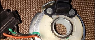
In a car with a carburetor, the sensor is located on the ignition distributor under the dust cover. It is secured to the base plate with two screws or rivets, depending on the valve type.
Relay and fuse diagram 2108
The relay and fuse box is located under the hood, in the compartment in front of the windshield on the left side.
Fuse block 2114-3722010-18
K1-relay for turning on headlight cleaners VAZ 2108; K2-relay-breaker for direction indicators and hazard warning lights; K3 - windshield wiper relay; K4-relay for monitoring the health of lamps; K5-power window relay; K6 - relay for turning on sound signals; K7-relay for turning on the electric heating of the rear window; K8-relay for high beam headlights; K9-relay for low beam headlights; F1-F16 - fuses.
Fuse block 2114-3722010-60
K1 - Headlight wiper relay, K2 - Turn signal and hazard warning relay, K3 - Windshield wiper relay, K4 - Brake light and parking light relay, K5 - Power window relay, K6 - Horn relay , K7 - Relay for turning on the heated rear window, K8 - Relay for turning on the high beam headlights, K9 - Relay for turning on the low beam headlights, F1 - F16 - VAZ 2108 fuses, F1 - F20 - Spare fuses.
Symptoms of a problem
If the Hall sensor is faulty, the VAZ 2109 engine experiences the following problems:
- the power unit does not start;
- interruptions in engine operation in different modes: jerking, disruption of the smoothness of the path;
- absence or violation of the minimum;
- the engine suddenly stops;
- loss of power.
Engine compartment of VAZ 2109
Troubleshooting Methods
To eliminate a malfunction in the carburetor, it is necessary to accurately determine that the cause of the malfunction is a faulty device. To do this, you need to check the Hall sensor on the VAZ 2109.
How to check the old one?
There are several ways to check the performance of the Hall sensor:
- The easiest way is to install a new one instead of the old one. If the car starts, the problem is solved; if not, then you need to look for the cause of the malfunction in other components of the ignition system.
- Measure the output voltage with a tester. With a working device, the value should be in the range from 0.4 to 11 volts.
- Simulation of the operation of the device: the three-pin lock is removed, the ignition is turned on, the third and sixth outputs are combined. If the spark goes out, this indicates a malfunction of the device.
Test device
There is another proven way to check without using a voltmeter.
It requires:
- connect the coil terminal to the spark plug;
- connect the wire on the spark plug to ground;
- remove the carriage with the sensor and connect the connector;
- turn on the ignition;
- use a screwdriver to bypass the device being tested, if the spark plug appears on the spark plug, the device is in good condition.
If the check reveals a malfunction of the regulator, it is necessary to replace the VAZ 2109 Hall sensor.
New replacement device
Types and scope of application
Despite the variety of elements that use the Hall effect, they can be divided into two types:
- Analogue, using the principle of converting magnetic induction into voltage. That is, the polarity and voltage directly depend on the characteristics of the magnetic field. Currently, this type of devices is mainly used in measuring technology (for example, as current, vibration, rotation angle sensors).
Hall effect current sensors can measure both AC and DC current - Digital. Unlike the previous type, the sensor has only two stable positions, indicating the presence or absence of a magnetic field. That is, operation occurs when the intensity of the magnetic field has reached a certain value. It is this type of device that is used in automotive technology as a sensor for speed, phase, camshaft position, as well as crankshaft, etc.
It should be noted that the digital type includes the following subtypes:
- unipolar - triggering occurs at a certain field strength, and after it decreases, the sensor returns to its original state;
- bipolar - this type reacts to the polarity of the magnetic field, that is, one pole turns the device on, and the opposite pole turns it off.
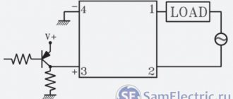
Example of using an analog element
Let us consider, as an example, the design of a current sensor whose operation is based on the Hall effect.
Simplified circuit of a current sensor based on the Hall effect
Designations:
- A is a conductor.
- B – open magnetic conductor ring.
- C – analog Hall sensor.
- D – signal amplifier.
The operating principle of such a device is quite simple: the current passing through the conductor creates an electromagnetic field, the sensor measures its magnitude and polarity and produces a proportional voltage UDT, which is supplied to the amplifier and then to the indicator.
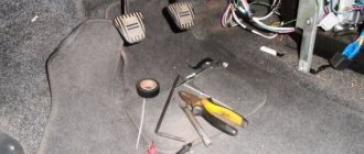
Replacement process
Not sure how to replace your device? — The procedure requires a set of tools.
To replace, it is necessary to remove the distributor from the group of additional equipment:
- first you need to disconnect the negative terminal from the battery;
- then you should disconnect the armored wire from the distributor, and also disconnect the hose from the vacuum corrector;
- then you need to remove the gas cable and put it aside;
- Having unscrewed the nut securing the bracket holding the wires, it must be removed from the stud and moved away so that it does not interfere;
- then make a straight line mark on the accessory drive housing and distributor to set the previous ignition timing when reinstalling;
- then you need to disconnect the block with wires;
- Having removed the cap from the hole in the clutch bell, turn the flywheel with a screwdriver so that the piston of the first cylinder takes the TDC position;
- Now, having unscrewed the two fastening nuts, you can disassemble the distributor.
The process of replacing the Hall sensor on a VAZ consists of the following steps:
- First, unscrew the distributor cap.
- Then remove the slider by slightly pulling it up.
- Next you need to disassemble the dust cover.
- After unscrewing the mounting bolt, you need to remove the plug.
- Next, unscrew the bolts holding the sensor plate.
- After unscrewing the bolts securing the vacuum corrector and removing the locking ring, it is necessary to disassemble the corrector and the rod.
- Once you open the clamp, you should take out the wires.
Unlock the clamp and remove the wires
After replacing the device, it is necessary to check the operation of the VAZ 2109 carburetor.