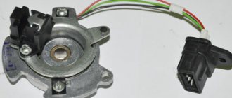
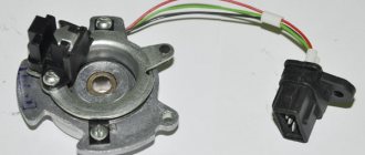
The Hall sensor is one of the most important elements in a car. It allows you to record information about the angle of deflection of the camshaft and crankshaft. With the help of charged particles, a magnetic field is formed, which is transformed through a metal tooth. The metal tooth already converts the signal, which is transmitted to the electronic control unit. Thanks to the received signals, the electronic control unit determines the top and bottom dead centers, and then regulates the supply of the fuel-air mixture.
On machines that can change the gas distribution mechanism, the Hall sensor allows you to determine the amount of distribution of the fuel mixture. Three terminals are connected to it:
- A terminal that is attached to the ground of the vehicle;
- A terminal that is fixed to the “plus” and has a voltage of 6 volts;
- The terminal that sends the converted signal to the electronic control unit.
If the Hall sensor malfunctions, the car has a number of specific problems that may indicate the need for replacement:
- The internal combustion engine may not start or may have problems starting;
- Engine idling may be accompanied by jerking or interruptions;
- When driving at high speeds, the car may twitch;
- The car may stall periodically while driving.
Hall sensor and other reasons: no spark on Audi 80 b4?
Updated: 2016-11-27 Author: audi39 Number of comments: 0
When faced with a lack of spark in an Audi 80 b4, car owners cannot always determine the cause of this problem immediately. When the engine begins to malfunction, power is lost, fuel consumption changes: in these cases, it is necessary to test the spark plugs.
Checking spark plugs on an Audi 80 can be done in the following ways:
- Checking for spark. After unscrewing the spark plug, you need to put a high-voltage wire on it and lean it against the engine. Checking for a spark occurs when the starter turns over.
- Using a multimeter. This method will only help determine the serviceability of the wires. The point is to measure resistance. If the indicator is below an acceptable value, the wire is faulty and needs to be replaced.
- With a special test gun. This device looks like a test bench for testing spark plugs under pressure. To check, you need to insert the part into the seat and cover it with a lid. Next, click on the button. If the indicator light on the device signals and a spark appears on the electrode, we can conclude that the spark plug is in good condition.
- Using a piezoelectric element. This mechanism can be made independently using a piezo module from a lighter. We press this device to the spark plug, and screw the running wire to its tip. We press the button. If the spark does not pass, replace the spark plug.
- Remove the wires one by one. This method involves disconnecting the wires going from the spark plug to the breaker-distributor one by one. Before removing the armor wire, you need to listen to the sound of the engine and remember it. After disconnecting the wire from the spark plug, listen to the sound of the engine again. We compare the first and second, if the sound has not changed, then a faulty spark plug has been found.
Distribution by type of Hall sensors
Hall effect sensors are divided into two main types. The first type is digital, the second is analog. They have significant differences in operation and design features.
Digital sensors
Digital DCs have only two positions, either zero or one. That is, when a certain magnitude of the magnetic field appears, the register is triggered. Such sensors are based on a device called a Schmitt trigger. It also has two stable positions - logical 0 and logical 1.
Sensors of this type are divided into three types:
- unipolar;
- bipolar;
- omnipolar.
Unipolar. The controller operates only if it is exposed to a magnetic field with a positive polarity of the south pole. The sensor is triggered and released only under this condition. Bipolar. This type of controller operates when exposed to both the south and north poles of the magnetic field. The peculiarity of the work is that the sensor is triggered from the south pole, and released from the north pole.
Omnipolar. The main feature is that they turn on and off when exposed to any of the poles of the magnetic field.
Analog sensors
Their uniqueness lies in the fact that, unlike digital ones, these controllers can output not two signal levels, but an infinite number. The functional feature is based on the conversion of magnetic field induction into voltage. Consists of a controller and a signal amplifier.
The principle of operation of the electric ignition system of the Audi 80 b4
A Hall sensor is installed under the distributor, to which the voltage goes. This sensor acts as a control wire that gives an impulse to the ECU. From the electronic control unit, adjustments and the required delays are sent, using data read from other engine sensors, to the switch, which is located next to the ignition coil. The switch acts as a transistor. When voltage is applied to the switch, the chain closes or opens, as a result, voltage is supplied to the coil and a spark is formed.
Each operation must be carried out with the ignition on. Measurements are taken with a multimeter.
Examination
The health of the Hall sensor can be checked in the following ways:
- By installing a known-good sensor in place of the one being tested. If the problems disappear when you start the engine, then the “original” sensor is faulty and needs to be repaired or replaced.
- Measurement of the sensor output voltage with a tester. A working device will show voltages ranging from 0.4 to 11 V.
- By creating an imitation of the sensor by removing the three-pin block from the distributor, connecting wires 3 and 6 of the switch output and turning on the ignition. A spark that appears indicates a breakdown of the sensor.
Checking the serviceability of the ignition coil
The first thing you need to check is the coil. It fails very rarely, but it is necessary to test it to rule out possible causes. In addition, it is not difficult to check; we immediately test the main winding, then the secondary one. On the top of the coil are the standard pin designations.
On the multimeter, select the lowest resistance reading. We measure the main winding, lean the tester terminals against the elements of the coil with external threads. The values should be within 1 - 1.5 Ohms.
The next measurement is carried out on the resistance in the secondary electrical winding. In this case, we will apply the probes to the external thread and the element that is located in the center of the coil cover. The measurements should be within 7 kOhm.
Are all values confirmed? This means the coil is normal. Let's move on to the next verification step. The values vary - replace the coil.
Examining the Switch
This device breaks down quite often. Therefore, it is necessary to test both the switch itself and its management. First of all, you need to remove the cover and measure the presence of voltage passing through it. You need to measure with the lid removed.
We lean the probes against the outer legs. The value should be close to the battery voltage, i.e. about 12 V. If there is no voltage, the most likely problem will be in the contacted ignition switch block or in the wiring that is connected to it.
Next, we check the passage of voltage through the ECU switch. With the cover removed, we lean the multimeter probes against the two outer legs and turn the starter. During these actions, voltage should appear on the device.
If voltage is present, then we further test the switch itself. It is necessary to put a cover on it, remove the rubber band for sealing and using a simple wire with the ignition on, we supply 12V from the battery to the second terminal. At the same time, the high voltage electrical wire from the coil must be applied with the other edge to any area of the body. At the hour at which voltage is applied, a spark is forced to appear. So we improvise the process of the ECU signal and the operation of the Hall device, and then straight away, throwing everything away, the control voltage arrives.
If there is no spark, it is necessary to replace the switch with a working one.
Hall sensor malfunctions
Let's move on. When there was no voltage at the second terminal, and the serviceability of the switch was checked, we came to the logical conclusion that the problem could be as follows:
- Hall sensor problem
- Problem with the electronic control unit
- There is a problem with the wiring that connects the Hall - the electronic control unit - the switch.
Let's start off easy. Let's see if voltage is supplied to the Hall sensor. To do this, remove the cover and start the ignition. Next, we measure the voltage by connecting the multimeter probes to the side terminals of the sensor. The device should show 10-11 V. If everything is normal, move on.
The next step will be to inspect the connected wiring Hall - electronic control unit - switch. You will need to remove the cover from the sensor and supply voltage to the second terminal from the battery with a spare wire. In the meantime, we lean the wire from the ignition coil with the other edge against a section of the body. When voltage is applied, the Hall sensor is improvised and a spark should appear. The presence of a spark indicates that the electronic control unit and wiring are in good condition. And most likely the problem lies in the Hall sensor itself.
Testing the sensor. The cover is inserted into the connector itself, remove the insulation from it and install the multimeter probes to the second and third legs of the cover. We rotate the starter, but it is not always possible to correctly determine the impulse. It is easier to install the head on the crankshaft pulley and slowly rotate the engine. The voltage on the multimeter is forced to change to 0 and 5-7 V. If this does not happen, then the problem is in the sensor and it needs to be replaced.
Causes of failure in the video:
How to replace
In order to replace the Audi 80 B3 Hall sensor, it is necessary to remove the cover and the distributor itself. After this, we set the mark of the gas distribution mechanism and the crankshaft at the same level and note what position the distributor was currently in. Next, using a key, we unscrew the fasteners and, if there are locking mechanisms, we also dismantle them. Afterwards it is necessary to dismantle the shaft and disconnect the contacts of the hall sensor. We unscrew the mechanism, pull the regulator towards us and take out the faulty device. Next, we install a working device and perform assembly in the opposite direction.
It is not recommended to repair the Hall sensor; it does not break down often - once every several hundred thousand kilometers. But its breakdown can cause significant inconvenience for the car owner. There are craftsmen who carry out repairs, but such sensors do not last long and soon also require replacement. Therefore, it is better to purchase a new device, because its cost is relatively inexpensive, around 1,500 rubles. But in the next few years, the owner of his car will not have to think about replacement.
So, I tormented all the stores in the city in search of a normal starter at an adequate price and seemed to have found it. When the very first small-scale dirty trick arrived, which had an awesome voltage drop, the thought crept into my mind to completely check all the ignition elements on my tank (well, what if, as they say). I dug up a bunch of manuals on the Internet, some of them are written very crookedly, some seem to be aimed at frying the machine’s brains... In general, it’s a mess. Having studied these manuals long and hard, I chose 100% working and safe methods for myself. And now I will tell you about them, maybe someone will find it useful like me (otherwise I was terribly stupid before this). I warn you, I will describe it in such a way that a person who climbed under the hood for the first time could understand it!
Everything is described provided that the injection works flawlessly, the wiring has not been burned or eaten, the engine is working, there is gasoline in the tank (yes, sometimes because of this the car also does not start))) in short, when everything works properly except the ignition.
Perform all actions only with full awareness of what you are doing!
It is best to look for a malfunction in the ignition system systematically along the chain: 1. Check whether the battery is charged and whether the generator is working. (use a tester/multimeter for this) 2. Check the fuses in the central switch. (special attention should be paid to fuses numbered 13, 21, 25, 27, 28 and 32, depending on the type of engine. You can see what these fuses are responsible for here. You can check it both visually and with a tester in dial mode. I prefer a tester because it is more reliable
. If a faulty fuse is found, replace it) 3. Perform a visual inspection. (in some cases, the malfunction is eliminated at this step. What are we looking for? Faulty wires, unconnected plugs, electrical breakdowns. If everything is in order, but the car does not start, then move on) 4. Check the ignition coil, Hall sensor or speed sensor, or ignition timing sensor depending on the engine. (I will write about this in detail below) 5. If the fault was not found in the previous steps, then you need to interrogate the memory of the fault memory.
Now let's take a closer look at step 4:
Checking the ignition coil
1. To check the resistance with the ignition off, disconnect all wires from the ignition coil. We measure the primary and secondary windings. (in the figure these are 1-15 and 1-4)
2. Measure the resistance between ignition coil terminals 1 (-) and 15 (+) with an accurate ohmmeter. 3. Standard resistance: 0.5 - 1.5 Ohm. 4. The next measurement is between terminals 1 (-) and 4 (distributor output). 5. Here the ohmmeter should show 5 - 9 kOhm. 6. If the above parameters are not achieved, the ignition coil should be replaced. 7. Using these measurements, it is impossible to determine a short circuit between the windings. Therefore, if, despite the good results obtained, you still consider the ignition coil to be the cause of the problem, you must take the removed ignition coil to a specialist for rechecking.
Checking the electronic switch next to the coil
1. Check the power supply to the switch. 2. Remove the chip from the switch.
3. Connect a voltmeter to the disconnected plug between pin 1 and pin 3. (if you don’t have a voltmeter, but you need to check whether the voltage is coming in or not, you can use a diode with a 1 kOhm resistor, you can’t use a light bulb, only a diode!)
4. Turn on the ignition. 5. The voltmeter should show a minimum of 11.5 V. 6. If the device does not show any voltage at all or is too weak, then the reason is in the wiring to the ignition switch. 7. If everything is normal, then check whether the signal is coming to the switch. 8. On the removed switch chip, connect the diode to connectors 2 (anode) and 3 (cathode). 9. Turn the starter, if everything is in order then the diode should blink, if not, read on. 10. We remove the middle contact from the chip, insert the chip back into the switch, remove the high-voltage wire from the coil to the distributor from the latter side and hold it so that the distance to ground is no more than 10 mm.
11. Turn on the ignition, apply a “-” or “+” signal to the 2nd contact, depending on the principle on which your distributor operates, a spark should appear. (For example, it appeared for me when a + pulse was applied to the middle contact of the switch) 12. If there is no spark, and there is a “+” on the 1st contact of the switch chip, “-” on the 3rd one, and the previously tested coil is working, then the switch is dead - replace it. 13. If a spark appears, the switch is working. 14. We return the previously removed middle contact to the chip and insert it back into the switch.
Checking the Hall sensor (hereinafter referred to as DH)
1. Check the power supply to the household. 2. Remove the chip from the DH.
3. Connect a voltmeter to the disconnected plug between pin 1 and pin 3. (if you don’t have a voltmeter, but you need to check whether the voltage is coming in or not, you can use a diode with a 1 kOhm resistor; you can’t use a light bulb, only a diode!) 3. Turn on the ignition. 4. The voltmeter should show a minimum of 9 V. 5. Otherwise, the control unit or wiring is faulty. 6. If everything is normal, then we check the serviceability of the DH. 7. Remove the rubber boot from the chip so that the contacts are accessible and connect the diode to the 2nd (anode) and 3rd (cathode) connectors. (the chip is plugged into the DC connector) 9. Turn the starter, if everything is in order, the diode should blink, if not, read on. 10. Connect a voltmeter to terminals 2 and 3. (the chip is plugged into the DH connector) 11. Turn on the ignition and slowly crank the engine by hand so that the perforated diaphragm (trigger) of the distributor rotates, enters the Hall sensor and exits it. 12. Monitor the measuring device: it should show 0-0.5 V if the diaphragm is outside the Hall sensor. When the diaphragm is inside the Hall sensor, the reading should be at least 4 V. 13. If there are no pulses, then the DC is faulty. (it often happens that it is not the sensor itself that has died, but the wires going to it)
I also came across this article on how to check that the dx works for me...
Mini check of the ECU and the line from the DC to the coil
1. Remove the plug from the DC. 2. Remove the high-voltage wire from the coil to the distributor cover from the latter side and hold it so that the distance to ground is no more than 10 mm. 3. Turn on the ignition. 4. Apply a “+” or “-” signal to the middle contact of the DC plug. (read which one exactly above, it worked for me when I supplied a plus) 5. In this case, the isk should appear and the fuel pump should start working, this means that the ECU sees a signal from the DC and when it comes, it turns on the fuel pump to supply fuel. 6. If nothing happens when a signal is applied to the middle contact, then there may be a malfunction in the ECU. (I’m not sure about the malfunction in the ECU and this point should be regarded only as my conjecture)
Hello everyone, having personally encountered the problem of a missing spark on a squirrel, I decided to write a short review on this topic, because there is little clear information to understand on the Internet, so I decided to describe the simplest test of the entire ignition system modularly. I’ll probably omit the point that you don’t have a spark, because the easiest way is to attach a wire from the coil next to the ground or an already unscrewed spark plug, in general this is the simplest and I won’t focus on this. For a general understanding of the ignition supply system: we have a hall sensor (located under the distributor), voltage is supplied to it and there is a control wire, which then sends a signal to the computer, which accordingly makes adjustments and the necessary delays by polling some engine sensors and sends a control signal to the switch (located near the ignition coil), the switch is an ordinary transistor which, when voltage is applied, closes/opens the circuit and accordingly supplies voltage to the coil and we have a spark.
Reminder: all manipulations with connections should be performed with the ignition turned off. All measurements are carried out with a conventional tester.
Let's check the coil
1)
The very first thing to start with is checking the coil. They usually fly extremely rarely, but it is easy to check, so we check the primary and secondary windings of the coil. The photo shows the typical designation of the terminals; in principle, they will also be marked on top and on the coil itself.
We measure the resistance of the primary winding, tester probes on pin 1 and pin 15 (the lowest threshold for measuring resistance is selected on the tester) - it should be within 1 - 1.5 Ohms. We measure the resistance of the secondary winding, tester probes for pins 1 and 4 - it should be around 7 kOhm. Is the coil working? - Go ahead. The indications are different, there is a break or short circuit - we change the coil.
Testing the switch
2)
Let's check the switch control and the switch itself; it breaks down quite often. First, let’s remove the chip from it and measure whether voltage is coming to it. Measure on the removed chip (pinout relative to the numbers of the switch itself.
Probes for legs 1 and 3 - should be around 12 V (approximate voltage of your battery). If there is no voltage, most likely the problem will be in the contact group of the ignition switch or in the wires themselves that go to it. Next, let’s check whether the voltage is coming to the switch and the ECU; again, on the removed chip, insert the tester probes into connectors 1 and 2 as in the photo and turn the starter - some voltage should jump through. 2.1)
If there is voltage, check the switch itself.
To do this, we put the chip on the switch itself, remove the rubber seal of the chip and take a regular wire with the ignition on and apply 12V to the 2nd terminal of the battery. At this time, we lean the high-voltage wire from the coil with the second end against some point of the body and at the moment when you apply voltage to the 2nd terminal, a spark should jump ( so roughly speaking, we simulate the operation of the hall sensor and the ECU signal and directly exclude everything by applying the control voltage
) and of course, if you don’t have a spark, then the switch needs to be replaced.
Hall sensor problems
3)
We go further if, after all, no voltage came to the switch chip as we previously checked on the 2nd contact, and after that we were convinced that the switch was working.
Accordingly, our problem remains either in the hall sensor, or with the computer, or with the wiring connecting the hall-ecu-switch combination. Let's start with something simple, check whether power is coming to the sensor itself, remove the chip - turn on the ignition, measure the voltage by connecting the tester probes to the 1st and 3rd terminals of the hall sensor, it should be about 10-11 V. There is voltage - that's good. 3.1)
Next, let’s check the hall-ecu-switch wiring connection; for this, on the removed hall sensor chip, we supply voltage from the battery with an additional wire to the 2nd terminal, at this moment we place the high-voltage wire from the coil with the second end next to a part of the body and at the moment the voltage is applied to The 2nd contact should spark a spark (
this is how we simulate the operation of the hall sensor itself
). If there is a spark, then the computer and wiring are normal and the problem is most likely in the sensor itself.
3.2)
Now let's check the hall sensor itself. The chip is connected to the connector itself, we move the insulation from the chip and connect the tester probes to the 2nd and 3rd connectors of the chip. You can turn the starter, but given the inertia of the testers, it is not always possible to reliably understand the impulse. It’s easier to put the head on the crankshaft pulley and slowly crank the engine - the voltage on the tester should change by 0 and 5-7 V depending on the position of the shutter in front of the hall sensor inductance coil. The problem with the hall sensor is very common, although often the chip itself breaks off and the connector wires themselves are cut by the shutter, so if there are no pulses from the sensor, first I advise you to disassemble the distributor and check the integrity of the wires from the coil itself to the connector; if all is well, then you will have to change it, It costs quite a bit and the entire distributor is usually sold at disassembly.
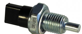
The need to check the Hall sensor arises when problems arise with the car’s ignition system, and therefore it is necessary to ensure that all its components are in good working order, in particular the idle air sensor. So let’s take a closer look at the principle of operation, signs of malfunction and how to check the Hall sensor with your own hands.
How to easily check the Hall sensor yourself: tools and instructions
Good day to all! Today I’ll tell you how to check a Hall sensor, what methods exist for assessing the condition of a device, and what you should pay attention to.
Motorists and those who ride a scooter and have a contactless ignition system or electronic ignition in their vehicle design have probably heard about this sensor or controller. It is also often called the camshaft position sensor or simply the camshaft position sensor.
The device is even found on phones. But since we have an automotive website, we will talk about the Hall sensor specifically in relation to cars and vehicles.
Before touching on the topic of verification methods, it would not be amiss to understand the very essence of the device in question, its functions and operating principle.
What it is
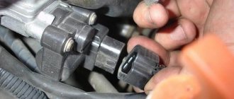
A Hall sensor is a controller that is located in the distributor and is one of its key components. The distributor, in turn, is a breaker-distributor.
The Hall sensor (HL) is located directly near the distributor shaft, where a special magnetically conductive plate is attached. Outwardly, it resembles a crown. This plate has exactly the same number of slots as the number of cylinders in a particular power plant. Therefore, if you have a car with 6 cylinders, then there will be exactly 6 slots. A permanent magnet is installed directly inside the controller.
Now regarding the principle of operation. If you understand this issue a little, you won’t see anything complicated here.
When the shaft rotates, the metal blades pass alternately through the slots in the controller in question, that is, in the DC. As a result of rotation, a pulse voltage is generated.
This voltage, due to the presence of a switch, goes directly to the ignition system coil. This is where the conversion process to high voltage takes place. As a result, it ends up on the spark plugs. The design of the DC provides for the use of 3 different terminals at once. The first serves to connect to ground, and the second receives a plus, receiving a voltage with a nominal value of about 6 V. There is also a third terminal from which the pulse signal goes to the switch after conversion.
Verification methods
You can use several diagnostic methods for the sensor located on the distributor.
Depending on the available means and capabilities, the motorist can check the current condition of the Hall controller with his own hands, evaluate its performance and make the appropriate decision on replacement.
As soon as you notice one or more of the symptoms presented, you should get checked. You can do it in several ways. I propose to consider them separately.
Wedge with wedge
The simplest and most effective method that does not require you to equip yourself with a tester or multimeter. But you will need a known-good similar Hall sensor.
The essence of diagnosis is outrageously simple. You remove the old controller and install a new one in its place. If after the manipulation the symptoms go away and engine operation returns to normal, then simply leave the new part in place. If you borrowed a DH from a friend or neighbor in the garage, remove the device, say thank you, and go to the auto parts store.
Voltmeter and multimeter
Using a voltmeter or a classic tester, you can easily check the condition of the device.
I think every motorist can use the tester. The task is to measure the voltage at the sensor output.
If the DC is in good condition, the tester will produce values in the range of 0.4-11 V.
A universal multimeter is used in exactly the same way. You just need to select the voltmeter mode on it.
Sensor simulation
Quite an interesting and effective method. But here you will have to do a little work with your own hands.
The principle of imitation is as follows. First, remove the block from the DH, which has 3 plugs. Next, start the ignition on the car, then connect outputs 3 and 6 to each other.
If a spark appears during such manipulation, then most likely the DC has failed.
Without testers
When testers are not available, testing can be done using a slightly different method.
Here you need to carry out step-by-step manipulations:
- the spark plug is connected to the wire terminal from the coil;
- the threaded part of the spark plug is connected to the ground;
- the carriage with the sensor is dismantled;
- connector is connected;
- the ignition is turned on;
- a metal object is held near the sensor;
- When a spark appears on the spark plug, the DH is operational.
Just be extremely careful when doing such manipulations with your own hands.
Homemade tester
You can assemble an analogue of the tester from practically available materials.
The testing device consists of a regular LED, a 1 ohm resistance and two pieces of flexible wiring that need to be soldered to the leg.
Wires are connected to terminals 1 and 3 of the DC plug box. If the polarity is correctly selected, the LED should light up. If not, try swapping. Now you need to do the following:
- the first wire on the first terminal remains in place;
- the wire from the third terminal is connected to the second terminal;
- the camshaft turns (using a starter or manually);
- The behavior of the diode is monitored.
If the diode starts blinking, then everything is fine with the ignition sensor, and there is no need to change it.
There are really quite a lot of verification methods. Choose according to your taste.
Have you ever had to check a Hall sensor? What diagnostic methods did you use and what was the result?
Subscribe, leave comments, ask questions and don’t forget to tell your friends about us!
Engine control system sensors (Hall and others) on an Audi 80
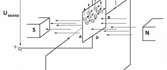
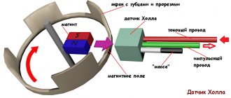
The Hall sensor takes its name from the name of the inventor who discovered the galvanomagnetic phenomenon in 1879.
Its essence lies in the occurrence of a potential difference when a conductor is placed in a magnetic field, which causes the flow of direct electric current to it.
The sensor uses the effect described above in the conditions of a conductor installed under voltage inside the device, which is affected by a magnetic field that crosses it across and creates an electromotive force.
The operating principle of the device is based on detecting the presence or absence of a magnetic field. When the induction force reaches a certain value, the sensor indicates the presence of a field.
If the indicator is below the set value, the sensor indicates its absence.
The sensitivity of the device is determined by the ability to detect a magnetic field of varying inductance, and can vary depending on the necessary requirements.
An automobile Hall sensor is designed to measure pulses, on the basis of which the electronics of the ignition control unit commands the formation of a spark at the required moment. Structurally, the device consists of the following parts:
Diagram of the fan control unit VAG 357 919 506
- Permanent magnet.
- Steel screen with several cut holes.
- Semiconductor wafers.
A connector containing 3 terminals comes out of the sensor:
- The first output is connected to ground.
- The second is for connecting 6 V voltage.
- The third one supplies the converted pulse signal to the switch.
In most cases, the sensor is located on the distributor. It detects the moment a spark is given and is used instead of contacts. There is a digital modification of the sensor, which can be bipolar or unipolar. The first type is triggered when the polarity changes, and the second when a field appears.
Signs of a Hall sensor malfunction
Malfunctions of the Hall sensor can have various symptoms, based on which even an experienced technician is not always able to immediately identify the failure. The most typical symptoms of sensor failure are as follows:
- The engine starts poorly or does not start at all.
- When driving a car at high speeds, jerking occurs due to engine operation.
- Engine idling is characterized by jerks and interruptions.
- The engine stalls when driving.
Examination
The health of the Hall sensor can be checked in the following ways:
- By installing a known-good sensor in place of the one being tested. If the problems disappear when you start the engine, then the “original” sensor is faulty and needs to be repaired or replaced.
- Measurement of the sensor output voltage with a tester. A working device will show voltages ranging from 0.4 to 11 V.
- By creating an imitation of the sensor by removing the three-pin block from the distributor, connecting wires 3 and 6 of the switch output and turning on the ignition. A spark that appears indicates a breakdown of the sensor.
How to check the Hall sensor?
It is recommended to carry out the test using a simple device that every driver can do with his own hands. He will need a resistance of 1 kOhm and a simple LED. A resistance is soldered to its leg, two pieces of any length of flexible wire convenient for operation are soldered to it, and the device is ready. Checking the Hall sensor is preceded by determining the presence of power supply to it:
- the distributor cap is removed;
- the plug box from the distributor is disconnected;
- the tester is connected to terminals 1 and 3, then the ignition is turned on.
If the car's electrical wiring is functioning normally, the tester will show a voltage of 10 volts or higher.
After this, we connect the designed device to the same terminals - the LED lights up if the polarity has been chosen correctly. Otherwise, you need to swap the ends of the wires. The subsequent verification scheme is as follows:
- We do not touch the wire connected to the 1st terminal, but we transfer the end from the 3rd to the free 2nd terminal;
- rotate (manually or with a starter) the camshaft.
If you notice that the LED blinks during this process, then the ignition sensor does not need to be replaced. It is also possible to check the Hall sensor with a multimeter. It is connected to the ignition output contact, setting the device to voltmeter mode. The device arrow should move in the range of 0.4-3 Volts (an indicator of the health of the sensor).
Expert opinion
Ruslan Konstantinov
Automotive expert. Graduated from Izhevsk State Technical University named after M.T. Kalashnikov, specializing in “Operation of transport and technological machines and complexes.” More than 10 years of professional car repair experience.
Replacing the support bearing of a VAZ 2110 on your own
Malfunctions of the Hall sensor manifest themselves in different ways; even experienced specialists are not able to accurately determine the failure. There are a number of symptoms, but they indicate problems with the sensor indirectly, because These signs happen for different reasons:
- the engine does not start;
- at idle speed fluctuates;
- while driving, when the speed increases, the car jerks;
- The engine stalls for no reason.
If such symptoms occur, it is necessary to also check the Hall sensor. In addition to the method indicated in the article, there are several more.
For example, the simplest thing is to ask someone for a working sensor and simply replace it on your car; if the problems go away on their own, then the sensor is faulty. If you have a multimeter at hand, checking is easier than ever.
To do this, you need to set the voltage measurement game mode on the device and test the indicators at the output of the sensor; if it is working properly, the voltage will vary from 0.4 to 11 V.
Another common method involves checking in the absence of sparking (if there is power in the ignition system) and involves simulating a sensor. The block is removed from the distributor and the ignition is turned on. Next, using a piece of wire, contacts 3 and 2 on the block are closed; if a spark appears on the central channel of the ignition coil, it means that the Hall sensor is faulty and requires replacement.
Hall sensor repair
The design of the Hall sensor is quite simple, and the device rarely fails. But when it breaks down, the car becomes immobilized, and the part requires urgent replacement.
Since the sensor is quite expensive, especially for foreign cars, it makes sense to try to repair it yourself.
For example, you can take a Volkswagen car device, which is installed on various models of cars from this automaker.
The most unreliable part of the sensor is the S441A logic element, which is the sensitive part of the device, which fails. The purpose of repair is to replace it. The procedure itself consists of the following steps:
- Purchasing a failed element or its equivalent.
2. Checking the part for functionality. For this purpose, an LED and a resistor (1 or 2 kOhm) are connected in series and attached to the “+” and “output” contacts. The current value should vary from 3 to 30 V, and the serviceability of the element is checked with a magnet: when exposed to it, the LED is activated.
3. Use a drill and a metal drill to make a hole in the center of the Hall sensor, cut the wires “flush” with a knife, and use a file to lay grooves from the hole made to the outputs of the remote wires.
4. Placing the active element in the completed window and checking its functionality. So, when the contacts are connected and the curtain passes through the slots, the LED should light up, and when the magnetic flux closes, it should go out.
5. If the circuit refuses to work, the element is turned over and tested again (the polarity of the location matters).
6. If the test was successful, the element leads are routed in the grooves of the housing. In the window itself, the wires that go to the connecting connector of the old sensor are soldered. Pay attention to the correct sequence of wires and their coincidence with the markings of the distributor connector (“+”, “0”, “-”).
7. Having completed soldering, check visually and with a tester for the absence of short circuits in the sensor. If the test is successful, seal the technological hole with heat-resistant glue.
8. The sensor is put in place and the circuit is checked for the absence of short circuits: none of the wires should contact the housing.
The sensors of many cars are restored in the same way. In addition to Volkswagen, devices for Daewoo, AUDI, Mitsubishi, etc. can be repaired, since their operating principle is the same in all cases.
Replacing the Hall Sensor Golf 2
replacing the original Hall sensor
Renault Logan: removing and replacing the heater motor
- for Volkswagen Golf 3
- To begin, remove the connectors using:
- Move them to the side so as not to interfere, remove the distributor cover (I think the wires should not be disconnected from it).
- Remove the slider and protective cover.
- At the top where the distributor is connected to the part of the engine, I suggest putting 2-3 hazards on so as not to knock out the ignition, but I recommend checking this later.
- Remove two screws.
Gently use your hands to rotate the distributor along its axis. Replacement of rear ABS sensor (Volkswagen Golf 4, Volkswagen Bora, etc.). Knowledge base “Brake system”, Forums of Volkswagen technical sites.
Then slide the distributor off the mounting pad using two screwdrivers. (Work with two screwdrivers at once to avoid misalignment.)
Clean it from dirt. Wipe off the oil.
Carefully install the distributor axis onto the edges of the defect, without squeezing the distributor itself, leaving a small gap between the edges of the defect and the distributor.
replacement sensor room, Volkswagen Golf 3, 1.3, 1993
- When inflammation tasks begin, in systems where it is used a Hall sensor
- , there is such a question.
- READ Replacing the Fan Sensor on VAZ 2107
Simple check of the sensor room! Simple test of the Hall sensor!
- In this video I set up the sensor. hall
- , and ignition timing vacuum, the cause of failure. my channel
- Hold the distributor shaft over the glass with one hand, put the drift on the pin with the other, knock the pin out with your third hand (partner) (it will tighten).
- The end of the pin cannot be knocked out, the main thing is that it comes out of the axis.
- You remember how the pin wheel is positioned to put it in the opposite position, otherwise your slider will rotate 180 degrees.
- Remove the axle with glass, remember the order in which all the washers are on the axle, unscrew the Hall sensor .
- rub the hall sensor
- needle files in the places where they are shown in the photo (if you have sandpaper, the task is easier, but you need to fine-tune the needle files).
- This is where you sand very carefully to avoid damaging the wires.
As a result, we grind it until the sensor snaps into place and the glass touches it.
I have a Golf 3 94 year old engine and here is a random hall sensor. Carefully pull the terminals using pliers (preferably blunt ones) from the VAZ connector and insert them into the VAG connector. Follow the polarity!
READ Replacing Fog Light Lamp Renault Megane 2
attached Hall sensor . Replacing the rear ABS sensor (Volkswagen Golf 4. It is advisable to place the washers wider under the screws. Replace them.
In this case, we will replace the original idle speed sensor of a Golf 3 with a 1.6 ABU engine with a hall from a VAZ 2108.
If you do not have the opportunity to install the original idle speed sensor (030905065B), since it costs about 1300 rubles. Alternatively you can use alternative. sensor VAZ hall
for 80 rubles
VAZ resistance sensor hall .
- Between (-) and (0) approximately 13.52 meg.
- Between (-) and () approximately 14.65 megamm.
To work you will need the following tool:
- 5 hex keys.
- Hammer (approximately 200-500 grams).
- Phillips PH2 screwdriver.
- Two middle slot screwdrivers.
- Drill diameter 3.9 mm.
- Average defect and much more.
- Files are flat and semicircular.
Hall sensor replacement
Replacing the Hall sensor is a fairly simple operation that even a novice car enthusiast can perform independently. All actions are carried out in the following order:
- Dismantling the distributor.
- Remove the distributor cover and align the timing marks with the crankshaft mark.
- Fix the position of the distributor, then use a wrench to unscrew the fasteners.
- Remove the stoppers and clips.
- Remove the shaft from the distributor.
- Disconnect the terminals on the sensor and unscrew it.
- Carefully pull out the faulty device through the gap created when the regulator was pulled back.
- Installation of a new Hall sensor is carried out in the reverse order.
How to replace
Having figured out how to check the Hall sensor, you can begin to replace it if, as a result of the diagnostic operation, its malfunction is determined.
This operation is performed in the following sequence:
- Remove the ignition distributor cover.
- Remove slider.
- Remove the DH connector fastening.
- Unscrew the screws of the support plate.
- Remove the sensor.
The new part is installed in the reverse order. After completing the operation, you will need to set the ignition timing. This operation is carried out using marks located on the crankshaft pulley, plastic casing and camshaft using a special strobe device.
After completing all the necessary adjustment work, you should start the engine, warm it up to operating temperature and drive the car for several kilometers. The engine must operate steadily both during acceleration and when driving at a constant crankshaft speed.
Self-repair of distributor (Hall sensor)
The information is applicable to repairing many vehicles.
The idea is not new, and not mine, but I decided to show it in pictures. It happens that the Hall Sensor stops working normally - then the car may either not start at all, or it starts according to the mood and works at random intermittently (that is, there is a spark, then there is no). It can be repaired very cheaply (a chip costs less than $1).
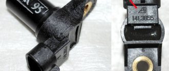
Removed sensor from Audi 2.0 5-cylinder engines. 2.3 (this particular sensor from Audi 100 C4, AAR engine) looks like this:
To check it, you need to connect the +12 battery to the red wire, “-“ to the brown wire, and between green and red - a multimeter in direct voltage (DC) measurement mode (or an LED that will light up and go out). In this case, the multimeter will show about 12V, and when the gap between the magnet and the sensor is blocked with a metal plate - 0V. Moreover, even if you tap on the sensor, everything should work stably. Faulty ones will either not work at all, or depend on a blow to them and turn on every other time. A faulty sensor must be replaced.
You can buy a new sensor assembly that will fit perfectly Huco 13 8156
- but its price tag is higher than the price of a new assembled distributor (Chinese
Patron P41-0002
) - and this will not make you very happy. We need a cheap solution and we have it.