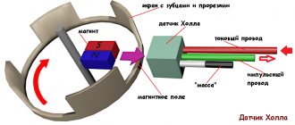
An electromagnetic device called a Hall sensor (hereinafter referred to as Hall sensor) is used in many devices and mechanisms. But its greatest application was found in the automotive industry. In almost all models of the domestic automobile industry (VAZ 2106, 2107, 2108, etc.), the non-contact ignition system for a gasoline engine is controlled by this sensor. Accordingly, when it fails, serious problems arise with the operation of the engine. In order not to make mistakes when diagnosing, it is necessary to understand the principle of operation of the sensor, know its design and testing methods.
Briefly about the principle of operation
The principle of operation of the ignition sensor is based on the Hall effect, which received its name in honor of the American physicist who discovered this phenomenon in 1879. By applying a constant voltage to the edges of a rectangular plate (A and B in Fig. 1) and placing it in a magnetic field, Edwin Hall discovered a potential difference at the other two edges (C and D).
Fig.1. Demonstration of the Hall effect
In accordance with the laws of electrodynamics, the Lorentz force acts on charge carriers, which leads to a potential difference. The Hall voltage value is quite small, ranging from 10 µV to 100 mV, it depends on both the current strength and the electromagnetic field strength.
Until the middle of the last century, the discovery did not find serious technical application until the production of semiconductor elements based on silicon, ultra-pure germanium, indium arsenide, etc., with the necessary properties, was established. This has opened up opportunities for the production of small-sized sensors that can measure both field strength and current flowing through a conductor.
Which to choose
Manufacturer Number Cost in rub.
| LADA | 21080-3706800-00 | 590 |
| AVTOVAZ | 21080370680082 | 240 |
| GALLANT | GLSS133 | 230 |
| AUTO ELECTRONICS | 21080370680000 | 195 |
| AVTOVAZ | 21080370680001 | 190 |
| REMCOM | RK02008 | 150 |
Factory products may have different endings in numbers, for example, 1, 2, 3 and so on. It's not fake. This is simply a product produced at a related enterprise of the Tolyatti auto giant.
Types and scope of application
Despite the variety of elements that use the Hall effect, they can be divided into two types:
- Analogue, using the principle of converting magnetic induction into voltage. That is, the polarity and voltage directly depend on the characteristics of the magnetic field. Currently, this type of devices is mainly used in measuring technology (for example, as current, vibration, rotation angle sensors).
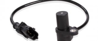
Hall effect current sensors can measure both AC and DC current - Digital. Unlike the previous type, the sensor has only two stable positions, indicating the presence or absence of a magnetic field. That is, operation occurs when the intensity of the magnetic field has reached a certain value. It is this type of device that is used in automotive technology as a sensor for speed, phase, camshaft position, as well as crankshaft, etc.
It should be noted that the digital type includes the following subtypes:
- unipolar - triggering occurs at a certain field strength, and after it decreases, the sensor returns to its original state;
- bipolar - this type reacts to the polarity of the magnetic field, that is, one pole turns the device on, and the opposite pole turns it off.
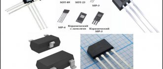
Appearance of a digital Hall sensor
As a rule, most sensors are a component with three pins, two of which are supplied with bi- or single-pole power, and the third is a signal one.
Example of using an analog element
Let us consider, as an example, the design of a current sensor whose operation is based on the Hall effect.
Simplified circuit of a current sensor based on the Hall effect
Designations:
- A is a conductor.
- B – open magnetic conductor ring.
- C – analog Hall sensor.
- D – signal amplifier.
The operating principle of such a device is quite simple: the current passing through the conductor creates an electromagnetic field, the sensor measures its magnitude and polarity and produces a proportional voltage UDT, which is supplied to the amplifier and then to the indicator. https://www.youtube.com/watch?v=fmLs9WsKx3I
Purpose of DC in the car ignition system
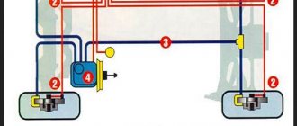
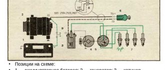
Having understood the principle of operation of the Hall element, let's consider how this sensor is used in the contactless ignition system of the VAZ line of cars. To do this, let's look at Figure 5.
Rice. 5. Principle of the SBZ device
Designations:
- A – sensor.
- B – magnet.
- C – plate made of magnetically conductive material (the number of protrusions corresponds to the number of cylinders).
The operating algorithm of such a scheme is as follows:
- When the chopper-distributor shaft rotates (moving synchronously with the crankshaft), one of the protrusions of the magnetically conductive plate takes a position between the sensor and the magnet.
- As a result of this action, the magnetic field strength changes, which causes the DC to operate. It sends an electrical impulse to the switch that controls the ignition coil.
- The voltage required to form a spark is generated in the Coil.
It would seem nothing complicated, but the spark must appear at a certain moment. If it forms earlier or later, it will cause a malfunction of the engine, even stopping it completely.
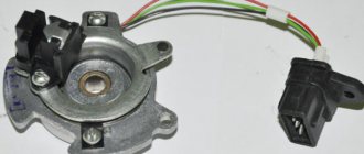
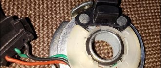
Appearance of the Hall sensor for SBZ VAZ 2110
Verification methods
You can use several diagnostic methods for the sensor located on the distributor.
Depending on the available means and capabilities, the motorist can check the current condition of the Hall controller with his own hands, evaluate its performance and make the appropriate decision on replacement.
As soon as you notice one or more of the symptoms presented, you should get checked. You can do it in several ways. I propose to consider them separately.
Wedge with wedge
The simplest and most effective method that does not require you to equip yourself with a tester or multimeter. But you will need a known-good similar Hall sensor.
The essence of diagnosis is outrageously simple. You remove the old controller and install a new one in its place. If after the manipulation the symptoms go away and engine operation returns to normal, then simply leave the new part in place. If you borrowed a DH from a friend or neighbor in the garage, remove the device, say thank you, and go to the auto parts store.
Manifestation of malfunction and possible causes
Irregularities in the operation of household farms can be detected by the following indirect signs:
- There is a sharp increase in fuel consumption. This is due to the fact that the fuel-air mixture is injected more than once during one crankshaft rotation cycle.
- Manifestation of unstable engine operation. The car may begin to “twitch” and a sharp deceleration occurs. In some cases, it is not possible to reach a speed of more than 50-60 km/h. The engine stalls during operation.
- Sometimes the failure of the sensor can lead to the transmission being locked, without the ability to shift it (in some models of imported cars). To correct the situation, a restart of the engine is required. In case of regular such cases, one can confidently state that the DP has failed.
- Often, a breakdown can manifest itself in the form of the disappearance of the ignition spark, which, accordingly, will make it impossible to start the engine.
- The self-diagnosis system may experience regular failures, for example, the check engine light will come on when it is idling, and the light will go out when the speed increases.
It is not at all necessary that the listed factors are caused by the failure of the DP. There is a high probability that the malfunction is caused by other reasons, namely:
- ingress of debris or other foreign objects onto the DP housing;
- the signal wire has broken;
- water has entered the DP connector;
- the signal wire is shorted to ground or the on-board network;
- the shielding sheath on the entire harness or individual wires is torn;
- damage to the wires supplying power to the DC;
- the polarity of the voltage supplied to the sensor is reversed;
- problems with the high-voltage circuit of the ignition system;
- problems with the control unit;
- the gap between the DC and the magnetic conductive plate is incorrectly set;
- Perhaps the reason lies in the high amplitude of the end runout of the camshaft gear.
Replacement
To make your own repairs, you need to be prepared. It is recommended to use a well-lit garage, and to dismantle the parts you will need a simple set of tools: a marker, a 10 mm wrench, a Phillips and flathead screwdriver. We will consider an example of replacing the hall sensor on a VAZ 2109 with dismantling the distributor. The step-by-step process is as follows:
- Secure the vehicle in gear or with the handbrake.
- Disconnect the negative terminal on the battery.
- Disconnect the high-voltage wires, marking with a marker which one was located.
- Remove the vacuum regulator hose.
- Disconnect the power supply from the hall sensor.
- Unscrew the top nut securing the distributor and wire bracket.
- Unscrew the bottom and rear mounting nuts.
- Use a marker to mark the location of the distributor so that you can install it back without unnecessary displacement and without adjusting the ignition timing.
- Move the distributor to the right along the studs.
- Take it to a well-lit workbench.
- Unscrew the screws of the ignition distributor cover and remove it.
- Remove the slider and plastic boot.
- Unscrew the plug screw.
- Remove the screws of the support plate.
- Remove the vacuum corrector (2 screws).
- Take out the block and wires.
- Remove the support plate with the sensor.
- Unscrew the two mounting screws on the DH and remove it.
- Install a new sensor.
- Collect everything in reverse chronology.
READ Honda CR-V checking the oil level in the automatic transmission
When disassembling the distributor, it is recommended to clean it of dirt using: injector cleaner, gasoline or acetone. It is most convenient to wash parts with a narrow paint brush. Inspect the ignition distributor cap very carefully. There should be no cracks on its body, and the contacts and ember should be in good condition.
How to check the performance of the Hall sensor?
There are different ways to check the serviceability of the SBZ sensor; we will briefly talk about them:
- We simulate the presence of DH. This is the easiest way to quickly check. But its effectiveness can only be discussed if a spark does not form when there is power at the main components of the system. To test, follow these steps:
- disconnect the three-wire plug from the distributor;
- we start the ignition system and at the same time “short” the wire with ground and the signal from the sensor (pins 3 and 2, respectively). If there is a spark on the ignition coil, it can be stated that the SBZ sensor has lost its functionality and needs to be replaced.
Please note that in order to detect sparking, the high-voltage wiring must be close to ground.
- Using a multimeter to check. This is the most well-known method, and is given in the car manual. You need to connect the probes of the device, as shown in Figure 7, and measure the voltage.
Connection diagram of a multimeter for checking DC
On a working sensor, the voltage will fluctuate in the range from 0.4 to 11 volts (do not forget to switch the multimeter to DC measurement mode). It should be noted that checking with an oscilloscope will be much more effective. It is connected in the same way as a multimeter. An example of an oscillogram of a working DC is shown below.
Oscillogram of a working Hall sensor SBZ
- Installation of a known working HH. If there is another sensor of the same type available, or it is possible to borrow it for a while, then this option also has a place to exist, especially if the first two are difficult to do.
There is another verification option, which is similar in principle to the second method. It can be useful if you don't have measuring instruments at hand. For testing, you will need a 1.0 kOhm resistor, an LED, for example, from a lighter flashlight, and several wires. From this entire set we assemble the device in accordance with Figure 9.
Rice. 9. LED tester for checking DH
We carry out testing according to the following algorithm:
- Check the power supply to the sensor. For this purpose, we connect (observing polarity) our tester to terminals 1 and 3 of the DC. Turn on the ignition, if everything is normal with the power supply, the LED will light up, otherwise you will need to check the power circuit (after making sure that the LED is connected correctly).
- Let's check the sensor itself. To do this, we “transfer” the wire from the first terminal to the second (signal from the DC). After this, we begin to turn the camshaft (by hand or with a starter). The blinking of the LED will indicate the serviceability of the DC. Otherwise, just in case, we check that the polarity is correct when connecting the LED, and if it is done correctly, we replace the sensor with a new one.
Search on the site
This is the Hall generator.
Everything is very simple. The next step is to carefully unsolder the legs of the element from the test circuit and connect it to the standard connector contacts.
You turn on the ignition.
The sensor circuit includes a power supply that converts unipolar supply voltage into bipolar power supply to the circuit. Pull out the pin using pliers. In a working device, the voltage will vary from 0.4 V to 11 V. Thanks to simple techniques, the motorist will save his time on repairs, and also eliminate unnecessary waste of money.
The impulses arise due to the fact that the slots do not go through the same distance, but through different ones, that is, they alternate. Replacing the sensor: instructions for motorists To install a new ignition sensor, you need to correctly remove the one that has failed. Resistors R1, R2 set the output current of our pulse sensor.
Disconnect the distributor cover. The third wire is used to transmit a signal, the polarity of which changes relative to the common power wire. Connect a voltmeter to the sensor output. The use of such a sensor will require monitoring the speed of the output shafts of gearboxes, monitoring the direction of rotation of two or more synchronized mechanisms, and accounting for fluid flow.
Magnetic field sensors. Hall sensors in MK circuits
We check the work again with a tester and at this point the work on repairing the Hall sensor can be considered complete. If it is impossible to install a working sensor, you can use a simple device that will duplicate its operation. But the Hall generator is most widely used in the automotive industry - for measuring the position of camshafts and crankshafts, as a non-contact electronic ignition and for other purposes. The first devices turned out to be quite bulky and not very ergonomic.
The use of neodymium magnets, the strongest permanent magnets, allows you to fit a sufficient number of small-sized magnets on the disk. Typically, replacing a Hall sensor consists of several steps: First of all, the distributor is removed from the machine. Also, do not exclude other ignition system malfunctions found in cars. The new Hall sensor is installed in the reverse order. The easiest way is to replace the device with a working one. installation of ignition with a hall sensor on a motorcycle. BASHKIRIA STERLITAMAK