02/09/2022 6 410 VAZ 2108
Author: Ivan Baranov
The Hall sensor of the VAZ 2108 is one of the important components that ensures the normal operation of the power unit. The purpose of this component is to transmit control signals to the switch, which converts these signals and supplies them to the ignition coil. We will tell you in more detail about malfunctions, as well as replacing the device, in this article.
[Hide]
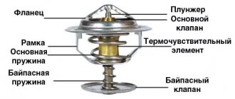
Design and principle of operation
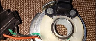
The controller design consists of the following parts:
- magnet;
- rotor;
- chip;
- plastic housing;
- conclusions;
- magnetic circuits.
The sensor operates based on the Hall effect. The principle of operation of the element is as follows:
- The rotor has four teeth that rotate while the engine is running.
- Pulses are constantly read.
- The received information in the form of a signal is sent to the switch.
- The pulse arrives at the installed coil.
- An increased voltage of 22–25 kV is supplied to the spark plugs.
The type of functioning is not complicated.
Types and scope of application
Despite the variety of elements that use the Hall effect, they can be divided into two types:
- Analogue, using the principle of converting magnetic induction into voltage. That is, the polarity and voltage directly depend on the characteristics of the magnetic field. Currently, this type of devices is mainly used in measuring technology (for example, as current, vibration, rotation angle sensors).
Hall effect current sensors can measure both AC and DC current - Digital. Unlike the previous type, the sensor has only two stable positions, indicating the presence or absence of a magnetic field. That is, operation occurs when the intensity of the magnetic field has reached a certain value. It is this type of device that is used in automotive technology as a sensor for speed, phase, camshaft position, as well as crankshaft, etc.
Connection diagram
The figure shows a basic electrical drawing for the VAZ 2108 and 2109 with pinout of contacts.
The ignition system operates as follows:
- The wire transmits voltage to the sensor from the switch through the red wire.
- A magnet creates a field.
- An impulse is supplied to the switch through the green wire.
Using a Hall element, the voltage directed to the high-voltage coil is regulated.
Hall sensor for VAZ 2108 and 2109 cars
The Tolyatti auto giant has been producing the first front-wheel drive VAZ family (Sputnik and Samara) for exactly 20 years. Over the years, cars have evolved slightly. For example, the carburetor was replaced by an injector, and the ignition system also changed. On the first and second generations of the car, even without an ECU, a hall sensor was installed, which frayed a lot of nerves for VAZ owners. Next, we will tell you where the hall sensor is located, what signs indicate its malfunction, as well as how to check and replace it.
Symptoms of a problem
Over time, the device becomes unusable. This can be recognized by the following signs:
- the engine runs poorly or stalls;
- the engine does not idle;
- car detonation is observed;
- While driving, the engine turns itself off.
Problems are not always serious. Sometimes the cause is simple oxidation of the contacts. It is enough to move them to restore engine operation. Such symptoms appear due to weakening of the sensor fasteners. To do this, it needs to be tightened. It happens that the reason lies in a short circuit in the wiring.
How can you tell if the sensor is broken?
Before checking the Hall sensor on the VAZ-2109, you need to determine whether it is to blame for all the troubles? The problem is that many of the symptoms of ignition system failures are similar to those that occur when the carburetor or timing drive malfunctions. Here are the main symptoms of a Hall sensor malfunction on the VAZ-2109:
- The engine refuses to start.
- There are interruptions in engine operation. Moreover, they occur in all modes. The smoothness of the ride is disrupted and jerking is felt.
- The idle speed is broken - the speed is unstable or the engine simply stops.
- Unexpected engine stops.
- Significant reduction in power.
If you notice one or more symptoms, you should check the ignition system. It is much easier to disassemble than a carburetor. Therefore, when troubleshooting, it is worth moving from the lesser “evil” to the greater.
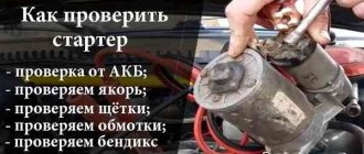
How to check
If you suspect a sensor malfunction, you can diagnose it as follows:
- Using a working element. The power is disconnected from the main sensor and connected to a new device. Then the central ignition wire is removed and placed on a metal surface. This is done to visually record the spark. The ignition turns on. To simulate the operation of the screen, a thin metal object is moved near the magnet. If a spark appears noticeably, it means that the original sensor was faulty.
- Using a multimeter. First, it is switched to voltmeter operating mode. The meter wires are connected to the element. When you move a metal object inside the sensor, the operation of the screen will be simulated. If the device shows a voltage change ranging from 0.4 V to 11 V, then the element is working.
- By creating a simulation of a new sensor. Power is disconnected from the element. The central wire of the distributor is removed and placed on ground to observe the spark. At the next stage, contacts “3” and “6” are closed and a spark is observed. A sensor malfunction is confirmed if it slips.
If such a check indicates a breakdown, then the element must be discarded and a new one installed.
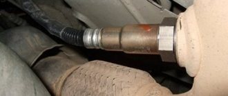
Checking the Hall sensor on VAZ 2108, 2109, 21099 cars
The hall sensor is installed in the ignition distributor of VAZ 2108, 2109, 21099 vehicles. It is designed to determine the moment of spark formation in the vehicle ignition system (analogous to the contacts in the contact ignition system). If the Hall sensor fails, the car engine will either not start at all or will start and stall. If such problems occur with the car engine, the Hall sensor should be checked.
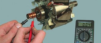
Hall sensor check
You can check it without removing it from the distributor. To carry it out, you will need a voltmeter or a similar device with a voltmeter mode and a pair of pins.
— We pierce the insulation of the green and white-black wires in the sensor connecting block with pins
The white-black wire is ground, the green wire is an impulse to the switch.
— Connect the voltmeter leads to the pins
— Turn on the car ignition
— Slowly rotate the engine crankshaft
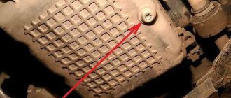
You can use a screwdriver to turn the flywheel splines in the hatch on the clutch housing.
— We monitor the voltmeter readings
When the crankshaft and the distributor slider rotate, respectively, the voltmeter readings should alternately drop to almost zero (0.4 V ) and rise to the voltage in the bot network or slightly lower ( 9-12 V ). If this happens, the Hall sensor is working and you should look for the fault somewhere else.
Checking the Hall sensor using a voltmeter
Notes and additions
If you don’t have a voltmeter, you can replace the Hall sensor with a known good one and evaluate the engine’s performance with it. To do this, you will have to remove, disassemble and reassemble the distributor, which is more labor-intensive.
— It is advisable to disconnect the wiring block from the Hall sensor with the ignition off, otherwise it may fail.
Source
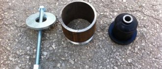
Replacement
When the check shows a malfunction of the sensor, then for removal you need to prepare a 10 mm wrench and a screwdriver. Procedure steps:
- Power is turned off from the device.
- The distributor is removed from the car.
- The device is placed on a workbench and the cover is removed.
- Carefully remove the boot with the slider.
- The plug screw is unscrewed.
- Remove the support plate screws.
- The vacuum corrector is dismantled. To do this, unscrew 2 screws.
- All wires are available.
- The sensor is removed along with the support plate.
- A new element is installed and installation is carried out in the reverse order.
During the replacement process, the entire internal space of the distributor must be thoroughly cleaned of dirt. As with flushing the carburetor, acetone is used for this.
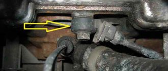
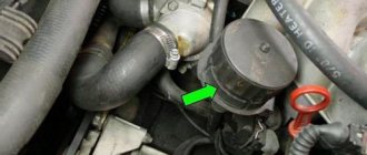
Where installed
The hall sensor is located inside the ignition distributor (distributor). The magnetic element is secured to the support plate, under the slider boot, with two screws. 3 wires come from it: red, green and black (positive, pulse, negative) and are connected to the block, which is secured with 1 screw at the exit from the distributor body. The pinout of the wires is in exactly this order.
Prices
For VAZ 2108–2109, the original number of the Hall device is product with article number 21080-3706800-00. If it is not available, pay attention to analogues. Possible options are presented in the table.
| vendor code | Manufacturer organization | Price in rubles |
| 21080-3706800-00 (original) | LADA | 590 |
| 21080370680082 (analog) | AVTOVAZ | 240 |
| GLSS133 (analog) | GALLANT | 230 |
| 21080370680000 (analog) | AUTO ELECTRONICS | 195 |
| 21080370680001 (analog) | AVTOVAZ | 190 |
| RK02008 (analog) | REMCOM | 150 |
The presented analogues are high-quality products that can be installed on a car.
Diagnostics of malfunctions of the ignition module of injection VAZ 2107
The ignition of the injection VAZ 2107 is completely electronic and is considered quite reliable. However, problems can arise with it too. The module plays an important role in this.
Signs of a malfunctioning ignition module
Symptoms of a faulty module include:
- the Check engine warning light on the dashboard lights up;
- floating idle speed;
- engine tripping;
- dips and jerks during acceleration;
- change in sound and color of exhaust;
- increased fuel consumption.
However, these signs can also appear in case of other malfunctions - for example, in case of problems with the fuel system, as well as in case of failure of some sensors (oxygen, mass air flow, detonation, crankshaft position, etc.). If the engine starts to operate incorrectly, the electronic controller puts it into emergency mode, using all available resources. Therefore, when the engine operation changes, fuel consumption increases.
In such cases, you should first of all pay attention to the controller, read information from it and decipher the error code that has occurred. To do this, you will need a special electronic tester, available at almost any service station.
If the ignition module fails, error codes in engine operation may be as follows:
- P 3000 - no sparking in the cylinders (for each cylinder the code may look like P 3001, P 3002, P 3003, P 3004);
- P 0351 - break in the winding or windings of the coil responsible for cylinders 1–4;
- P 0352 - a break in the winding or windings of the coil responsible for 2–3 cylinders.
At the same time, the controller can produce similar errors in the event of a malfunction (break, breakdown) of high-voltage wires and spark plugs. Therefore, before diagnosing the module, you should check the high voltage wires and spark plugs.
Main malfunctions of the ignition module
The main malfunctions of the VAZ 2107 ignition module include:
- a break or short to ground in the wiring coming from the controller;
- lack of contact in the connector;
- short circuit of the device windings to ground;
- break in the module windings.
Checking the ignition module
To diagnose the VAZ 2107 injection module, you will need a multimeter. The verification algorithm is as follows:
- Raise the hood, remove the air filter, find the module.
- We disconnect the block of the wiring harness coming from the controller from the module.
- We set the multimeter to measure voltage in the range 0–20 V.
- Without starting the engine, turn on the ignition.
- We connect the negative (usually black) probe of the multimeter to ground, and the positive one to the middle contact on the harness block. The device must display the voltage of the on-board network (at least 12 V). If there is no voltage or it is less than 12 V, the wiring or the controller itself is faulty.
- If the multimeter shows a voltage of at least 12 V, turn off the ignition.
- Without connecting the connector with wires, disconnect the high-voltage conductors from the ignition module.
- Switch the multimeter to resistance measurement mode with a measurement limit of 20 kOhm.
- To check the device for an open circuit in its primary windings, we measure the resistance between contacts 1a and 1b (the outermost ones in the connector). If the resistance of the device tends to infinity, there is indeed an open circuit in the circuit.
- We check the module for breaks in the secondary windings. To do this, we measure the resistance between the high-voltage terminals of the first and fourth cylinders, then between the terminals of the second and third cylinders. In operating condition, the module resistance should be about 5–6 KOhm. If it tends to infinity, the circuit is broken and the module is faulty.