Principle of operation
Hydraulic dual-circuit brakes with diagonal distribution are predominantly efficient and reliable. This is due to the fact that if one circuit fails, the second will allow your car to brake.
The circuit system is arranged as follows - one of them is responsible for the left rear and right front wheel, and the second circuit is responsible for the left front and right rear wheel.
This way, you will be able to brake without damaging the brakes or causing other problems with the system.
Braking system design
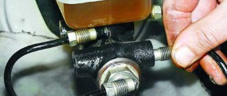
The most important component of the VAZ 2110 brake system circuit is a vacuum booster and a dual-circuit regulator. The latter is responsible for creating pressure in the rear brake devices.
The brake drive is equipped with a piping system, which is divided into two circuits, brake devices and hoses. They allow the front and rear wheels to brake.
To activate the braking system, a special pedal is located inside the passenger compartment at the driver’s feet. In the VAZ 2110 car it is located in the middle.
The main elements of the hydraulic drive are:
- Vacuum booster. Its design helps create pressure directed towards the master cylinder piston. This creates a braking effect.
- Pressure regulator drive. Through it, the brake fluid is directed to the rear devices of the braking system.
- Directly the brake pressure regulator of the VAZ 2110. Its function is to be responsible for the pressure force. The unit reduces or increases this indicator, depending on the load on the rear axle of the car.
- Master cylinder with reservoir and pistons. On the filler neck of this tank there is a sensor that monitors the emergency level of brake fluid.
- Front wheel brake mechanism. Its design includes cylinders, pads and a disc, plus a special alarm that warns of wear or malfunction of the lining.
- Rear wheel brake mechanism. Here the system is not disk, but drum. At least, this is the design the factory envisages. Some VAZ 2110 owners believe that drum mechanisms are not reliable and efficient enough, and therefore install disk devices in their place.
Which master brake cylinder is better for the VAZ-2110
The main brake cylinder of the VAZ-2110 can be repaired, but not always.
Currently, many companies produce analogues of the VAZ-2110 GTZ. Most of them are a higher quality product than recommended by the manufacturer.
Products from Fenox or Kraft are in great demand.
For aesthetes, we can recommend a product from Bosch, which costs three times more. In addition, many manufacturers produce parts with or without a tank.
Fenox
Brake cylinder FENOX T2043C3
For example, the company Fenox GTZ has the following article numbers:
- FENOX T2043C3 – this part is without a tank;
- FENOX T2043.5C3 – with tank.
Since the difference between these modifications is small, it is better to purchase a GTZ with a tank, especially if the old one contains dirt that is very difficult to remove.
Why do you need a pressure regulator?
Not every owner of a domestic “ten” will understand why the brake pressure regulator on a VAZ 2110 needs to be replaced. Simply, this name is not familiar to everyone. A popular designation for a regulator is a sorcerer.
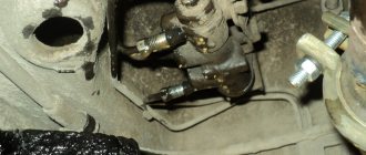
This very sorcerer is located on the rear suspension of your car. It has a lever with a movable position. Depending on the moment of load on the spring, its position changes.
The voltage generated during actuation is directed and distributed to the brake piston. Pressing the piston pedal reduces the load on the rear pads. If the brake system is working properly, the loads are distributed evenly.
In order for the unit to function efficiently and without errors, it is necessary to adjust the brake pressure regulator on your VAZ 2110. This way you can prevent untimely wheel locking.
The device of the brake system on the VAZ 2110
On a VAZ 2110 car, the brake system has a hydraulic dual-circuit drive. It’s no secret that you can’t go far in a car without brakes and safety in this case is close to zero.
Today we will talk to you about how the brake system works on the domestic VAZ 2110 car, or, more simply, the “ten”, we will analyze its main malfunctions, as well as ways to eliminate potential and existing problems.
Improvement of the braking system
Many VAZ 2110 owners agree that the factory brake system is far from perfect. Therefore, they decide to modernize and improve the unit using technical tuning.
A popular solution to the issue of brake efficiency is to replace drum mechanisms with disc ones. Of course, in the case of the “ten” we are talking about the rear wheels. When replacing brakes, be sure to take into account the fact that the rear wheels must brake more softly and somewhat later than the front wheels. This way the car won't skid and you won't fly off the road.
Another option is to remove the factory brake master cylinder and vacuum booster. Instead, units from Priora are excellent. Such tuning will eliminate vibrations and also allow you to use the brake pedal effectively and without excessive effort.
Regardless of the changes made to the brake system, after each modification it is mandatory to pump the brakes.
Master brake cylinder
Now let's talk about the master brake cylinder on a VAZ 2110 car. If you do not want to allow the brakes to fail while driving, they should be checked periodically, and if problems arise, take appropriate action immediately.
A common reason for replacing the master brake cylinder of a VAZ 2110 is precisely the fact that the brakes are lost.
Symptoms of a problem
Of course, brakes can completely lose their effectiveness for various reasons, but now we are talking specifically about the master cylinder. If the reason lies therein, then it can be determined by the following signs:
- The master cylinder shows signs of brake fluid leakage;
- The pedal has an idle motion, that is, when it is pressed, no force is created;
- The brake pedal simply won't press.
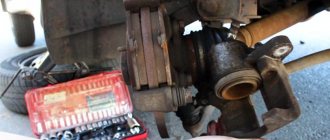
Replacement
The most difficult process is disassembly. Therefore, let's talk about it in more detail.
- Carefully disconnect the master cylinder from the pipeline.
- Disconnect the block, which is equipped with wiring, from the emergency brake fluid indicator. The connection to the “ten” is made by terminals.
- Cover the pipe and assembly openings with something to prevent brake fluid from leaking. It will pollute the interior space, which is undesirable.
- Now remove the cylinder along with the reservoir. To do this, simply unscrew the fastening nuts that connect the element to the vacuum booster.
- After removing the brake fluid level sensor, drain the brake fluid present from the cylinder and the cylinder itself.
- If there is no serious need, you should not remove the tank. But for complete assembly, the tank is removed and then installed in place in strict order.
- Before reassembly, each element is washed with purified brake fluid. A good alternative is isopropyl alcohol.
- Do not forget to dry the parts with a compressor and wipe with a clean, dry cloth.
- Carefully avoid contact of the main cylinder with fuel or kerosene.
- Pay special attention to the O-rings. If you wash them with special alcohol, do not keep the rings in this liquid for more than 20 seconds. After processing, immediately dry and wipe the seals.
- Treat the surface of the piston and mirror to remove all rust.
- When replacing the master cylinder, new O-rings must be installed, regardless of their current condition.
- Check the elasticity of the piston springs under load. Refer to the VAZ 2110 repair manual, which indicates the appropriate loads and forces for testing.
- When free, the length of the spring should be 59.8 millimeters. If the indicator deviates from the norm, be sure to replace the springs.
Leveling up
If you think that after replacing the brake master cylinder you can safely go out on the roads, then you are mistaken. In fact, a complete repair of brake cylinders on a VAZ 2110 includes bleeding.
Problems and their solutions
There are several common problems associated with brakes on a VAZ 2110 car. The reasons for their occurrence may be different, but the solution is always the same - timely and high-quality repairs.
- The brakes have completely lost their effectiveness, pressing the pedal does not cause any reaction. In such a situation, it is categorically impossible to drive anywhere under your own power, even if we are talking about a trip to a service station? How do you brake? About a wall or pillar? Call a tow truck and start repairs. In some situations, the problem can be solved on the spot, but these are temporary measures.
- During braking, strong vibrations are observed, most often in the steering column. At the same time, when you press the pedal, it is difficult to hold the steering wheel in your hands. There may be several reasons for this: If you have non-ventilated discs installed, similar situations may arise during rain or when braking through a puddle. Such devices do not like moisture, so to get rid of vibrations, replace the disks with ventilated ones;
- Another cause of vibrations is faulty drums. If there are dark spots on the working surface of the drums, the unit wears unevenly. Immediate repair or complete replacement of mechanisms is required;
- Be sure to check for signs of deformation on the front brake discs. They often cause vibrations.
- The vacuum booster air filter may be clogged, causing the brake pedal to feel stiff;
As you can see, the brake system of the VAZ 2110 car is far from perfect in its factory version, but it performs its functions effectively and reliably. All possible malfunctions can easily be fixed independently, but in some situations it is advisable to contact a professional service station.
Basic faults
Despite the simplicity of the design and the small number of moving elements, the GTZ often ceases to perform its functions normally due to malfunctions.
It is not difficult to detect a breakdown of the GTZ. The first signals of a malfunction will be given by the brake pedal. Any change in its behavior when pressed (lightness, increase in force, etc.) indicates a breakdown. But it will signal the emergence of problems throughout the system. Checking the system on the highway allows you to more accurately identify the malfunction (the car accelerates, and then emergency braking is performed). And then the traces determine how the system works. Afterwards, all that remains is to visually inspect all the components of the drive for leaks.
The main malfunctions of the master brake cylinder are:
- Depressurization.
- Air leak.
- One of the pistons is jammed.
The master cylinder loses its seal, usually due to severe wear or damage to the sealing collars. In this case, liquid can flow between the chambers and also come out of the housing. This allows air to enter the system. As a result, the pressure decreases significantly and the effectiveness of the braking system deteriorates.
Video:Replacing the master brake cylinder VAZ 2108 2109 2110
Air leaks in the system may occur due to blockage of the ventilation hole in the tank lid. Because of this, when the liquid moves, a vacuum is formed in the tank, which is compensated by air penetrating through the cuff. As a result, airing of the system causes a decrease in the efficiency of the system.
Piston jamming can occur for two reasons - debris entering the cylinder through the tank or the formation of rust on the internal surfaces of the housing. This causes one of the circuits to stop working.
Restoring the performance of the gas turbine engine is possible only in case of wear or damage to the seals or clogging. Special repair kits are sold for repairs.
Often, washing the cylinder and replacing rubber elements allows you to completely restore functionality. But there are also cases when such measures do not help and the problem can only be solved by replacing the assembly.
Hydraulic brake circuit diagram
1 – front wheel brake mechanism; 2 – pipeline of the “left front–right rear brake” circuit; 3 – main cylinder for hydraulic brakes; 4 – pipeline of the “right front–left rear brake” circuit; 5 – master cylinder reservoir; 6 – vacuum booster; 7 – rear wheel brake mechanism; 8 – elastic lever of the pressure regulator drive; 9 – pressure regulator; 10 – pressure regulator drive lever; 11 – brake pedal; A – flexible hose of the front brake; B – flexible rear brake hose
The car uses a working brake system with diagonally separated circuits, which ensures high active safety of the car. One hydraulic drive circuit ensures the operation of the right front and left rear brake mechanisms, the other - the left front and right rear.
If one of the circuits of the service brake system fails, the second circuit is used to stop the vehicle with sufficient efficiency.
The hydraulic drive includes a vacuum booster 6 and a dual-circuit pressure regulator 9 for the rear brakes.
The parking brake system is driven by the brake mechanisms of the rear wheels.
Master brake cylinder. Purpose, device
The main element of the hydraulic drive is the brake master cylinder (MBC). It is thanks to him that the mechanical action is converted into brake fluid pressure. It also separates the entire braking system along its contours, which is very important.
The main condition for the normal functioning of the hydraulic drive is the tightness of the system. If the pipelines break down due to a leak, the entire system will stop working. To avoid a complete failure of the system, it was divided into two circuits independent of each other. Each of them combines two brake mechanisms. As a result, if the pipeline of one of the circuits is damaged, the second remains sealed and the mechanisms to which it is connected continue to perform their function. And although the efficiency of the system decreases, the car still retains the ability to brake.
The design and operating principle of a dual-circuit gas turbine engine are quite interesting. And although they may differ in appearance, the internal structure of all main cylinders is almost the same.
There is a cavity made inside the body and channels for connection with pipelines (leading to the brake mechanisms) and a reservoir from where fluid is supplied. In this cavity there are two pistons installed one behind the other. They act on the liquid. To ensure that the pistons return to their original position after the pedal is released, they are both spring-loaded. Moreover, the spring stop of the first piston is the second one. The spring of the second piston rests against the end wall of the housing cavity.
Since each of the pistons is responsible for supplying liquid only to its own circuit, the entire cavity is divided into two chambers (one is located between the pistons, the second is between the piston and the housing wall). To ensure the tightness of each of them, rubber sealing elements are installed on the pistons.
Each of the working chambers is connected to the tank by two channels - compensation and bypass. Thanks to them, the amount of fluid in the system is replenished and the formation of vacuum and air in the system is prevented when the pedal is released. Also, two pipelines are connected to the chamber, each of which leads to its own brake mechanism.
Video: Brake master cylinder
The tank can be attached directly to the GTZ body or be remote (in this case it is connected to the cylinder by pipelines). The liquid from it is supplied to both circuits, but there is a partition inside the tank that separates the liquid between the circuits. This is necessary so that in the event of a depressurization of the system, all the liquid does not leak out.
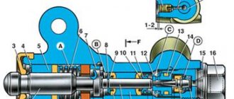
Vacuum booster
1 – vacuum booster housing;
2 – amplifier housing cup; 3 – rod; 4 – adjusting bolt; 5 – rod seal; 6 – sealing ring of the master cylinder flange; 7 – diaphragm return spring; 8 – amplifier pin; 9 – tip mounting flange; 10 – valve; 11 – hose tip; 12 – diaphragm; 13 – amplifier housing cover; 14 – sealing cover; 15 – piston; 16 – protective cover of the valve body; 17 – air filter; 18 – pusher; 19 – pusher return spring; 20 – valve spring; 21 – valve; 22 – valve body bushing; 23 – rod buffer; 24 – valve body; A – vacuum chamber; B – atmospheric chamber; C, D – channels The rubber diaphragm 12 together with the valve body 24 divides the cavity of the vacuum amplifier into two chambers: vacuum A and atmospheric B. Chamber A is connected to the engine inlet pipe through the check valve of the tip 11 and a hose.
The 24 valve body is plastic. At the exit from the cover, it is sealed with a corrugated protective cover 16. The valve body contains the main cylinder drive rod 3 with a support sleeve, rod buffer 23, valve body piston 15, valve assembly 21, pusher and valve return springs 19 and 20, air filter 17 , pusher 18.
When you press the pedal, the pusher 18, the piston 15, and after them the valve 21 move until it stops against the seat of the valve body. In this case, cameras A and B are separated. As the piston moves further, its seat moves away from the valve and through the resulting gap, chamber B is connected to the atmosphere. The air entering through filter 17, the gap between the piston and the valve and channel D creates pressure on the diaphragm 12. Due to the difference in pressure in chambers A and B, the valve body moves along with the rod 3, which acts on the piston of the main cylinder.
When the pedal is released, valve 21 moves away from the body seat and through the resulting gap and channel C of chambers A and B communicate with each other.
Pressure regulator drive
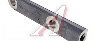
1 – pressure regulator; 2, 16 – pressure regulator mounting bolts; 3 – bracket for the pressure regulator drive lever; 4 – pin; 5 – pressure regulator drive lever; 6 – axis of the pressure regulator drive lever; 7 – lever spring; 8 – body bracket; 9 – pressure regulator mounting bracket; 10 – elastic lever of the pressure regulator drive; 11 – earring; 12 – earring bracket; 13 – washer; 14 – retaining ring; 15 – bracket pin; A, B, C – holes
Pressure regulator
1 – pressure regulator housing;
2 – piston; 3 – protective cap; 4, 8 – retaining rings; 5 – piston sleeve; 6 – piston spring; 7 – body bushing; 9, 22 – support washers; 10 – sealing rings of the pusher; 11 – support plate; 12 – pusher bushing spring; 13 – valve seat sealing ring; 14 – valve seat; 15 – sealing gasket; 16 – plug; 17 – valve spring; 18 – valve; 19 – pusher bushing; 20 – pusher; 21 – piston head seal; 23 – piston rod seal; 24 – plug; A, D – chambers connected to the main cylinder; B, C – chambers connected to the wheel cylinders of the rear brakes; K, M, N – clearances The pressure regulator regulates the pressure in the hydraulic drive of the brake mechanisms of the rear wheels depending on the load on the rear axle of the car. It is included in both circuits of the brake system and through it brake fluid flows to both rear brake mechanisms.
Pressure regulator 1 (Fig. Pressure regulator drive) is attached to bracket 9 with two bolts 2 and 16. At the same time, front bolt 2 simultaneously secures fork bracket 3 of lever 5 of the pressure regulator drive. A double-arm lever 5 is hinged on the pin of this bracket with a pin 4. Its upper arm is connected to an elastic lever 10, the other end of which is pivotally connected to the rear suspension arm bracket through an earring 11.
Bracket 3 together with lever 5 can be moved relative to the pressure regulator due to the oval holes for the fastening bolt. This regulates the force with which lever 5 acts on the regulator piston (see subsection 6.4.2). The regulator has four chambers: A and D (Fig. Pressure regulator) are connected to the main cylinder, B to the left, and C to the right wheel cylinders of the rear brakes.
In the initial position of the brake pedal, piston 2 (see Fig. Pressure regulator) is pressed by lever 5 (see Fig. Pressure regulator drive) through leaf spring 7 to pusher 20 (see Fig. Pressure regulator), which is pressed against the saddle under this force 14 of valve 18. In this case, valve 18 is pressed away from the seat and a gap H is formed, as well as a gap K between the piston head and seal 21. Through these gaps, chambers A and D communicate with chambers B and C.
When you press the brake pedal, fluid flows through gaps K and H and chambers B and C into the wheel cylinders of the brake mechanisms. As the fluid pressure increases, the force on the piston increases, tending to push it out of the housing. When the force from the liquid pressure exceeds the force from the elastic lever, the piston begins to move out of the body, and after it, under the action of springs 12 and 17, the pusher 20 moves together with the sleeve 19 and rings 10. In this case, the gap M increases, and the gaps H and K decrease . When the gap H is completely selected and the valve 18 isolates chamber D from chamber C, the pusher 20, together with the parts located on it, stops moving after the piston. Now the pressure in chamber C will vary depending on the pressure in chamber B. With a further increase in the force on the brake pedal, the pressure in chambers D, B and A increases, piston 2 continues to move out of the body, and sleeve 19 together with o-rings 10 and plate 11 under increasing pressure in chamber B, it shifts towards plug 16. At the same time, the gap M begins to decrease. Due to the decrease in the volume of chamber C, the pressure in it, and therefore in the brake drive, increases and will be practically equal to the pressure in chamber B. When the gap K becomes zero, the pressure in chamber B, and therefore in chamber C, will increase less degree than the pressure in chamber A due to throttling of the liquid between the piston head and seal 21. The relationship between the pressure in chambers B and A is determined by the ratio of the difference in the areas of the head and piston rod to the area of the head.
As the vehicle load increases, the elastic lever 10 (see Fig. Pressure regulator drive) is loaded more and the force from lever 5 on the piston increases, that is, the moment of contact between the piston head and seal 21 (see Fig. Pressure regulator) is achieved at greater pressure in the main brake cylinder. Thus, the effectiveness of the rear brakes increases with increasing load.
If the brake circuit “left front – right rear brake” fails, the o-rings 10, bushing 19, under the fluid pressure in chamber B, will move towards the plug 16 until the plate 11 rests on the seat 14. The pressure in the rear brake will be regulated by part of the regulator, which includes piston 2 with seal 21 and bushing 7. The operation of this part of the regulator, in the event of a failure of the said circuit, is similar to the operation with a working system. The nature of the change in pressure at the outlet of the regulator is the same as with a working system.
If the brake circuit “right front – left rear brake” fails, the pressure of the brake fluid forces the pusher 20 with the bushing 19 and sealing rings 10 toward the piston, pushing it out of the housing. The M gap increases and the H gap decreases. When valve 18 touches seat 14, the increase in pressure in chamber C stops, that is, the regulator in this case works as a pressure limiter. However, the achieved pressure is sufficient for reliable operation of the rear brake.
There is a hole in housing 1, closed by plug 24. Liquid leakage from under the plug when it is squeezed out indicates a leak in rings 10.
Brake system VAZ 2110
Home • VAZ • 2110 • Brake system
Brake system structure of the VAZ 2110: 1 – main cylinder of the hydraulic brake drive, 2 – pipeline of the “right front – left rear brake” circuit, 3 – flexible hose of the front brake, 4 – reservoir of the master cylinder, 5 – vacuum booster, 6 – pipeline of the “left” circuit front - right rear brake, 7 - rear wheel brake mechanism, 8 - elastic pressure regulator drive lever, 9 - flexible rear brake hose, 10 - pressure regulator, 11 - pressure regulator drive lever, 12 - brake pedal, 13 - front brake mechanism wheels.
The service brake system of the VAZ 2110 is hydraulic, dual-circuit (with diagonal separation of the circuits), with a pressure regulator, a vacuum booster and an indicator of insufficient brake fluid level in the reservoir. If one of the brake system circuits fails, the second circuit provides braking of the vehicle, although with less efficiency.
The brake mechanisms of the front wheels of the VAZ 2110 are disc (on VAZ 21103, 21113 and 2112 cars - ventilated), with a single-piston floating caliper and a brake pad wear indicator. The brake mechanisms of the rear wheels of the VAZ 2110 are drum brakes, with two-piston wheel cylinders and automatic adjustment of the gap between the shoes and the drum. The automatic clearance adjustment device is located in the wheel cylinder.
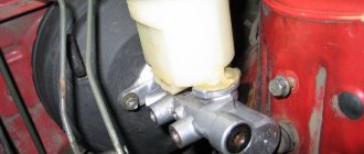
The main brake cylinder of the VAZ 2110 is attached to the vacuum booster housing on two studs. A translucent polyethylene tank with an emergency fluid level sensor is inserted into the holes in the upper part of the cylinder on rubber seals. The tank has markings for maximum and minimum fluid levels. Two screws are screwed into the bottom of the cylinder to limit the movement of the pistons. The screws are sealed with copper gaskets. In the front part of the cylinder (along the direction of the car) there is a plug screwed in that serves as a stop for the return spring, also sealed with a copper gasket. The pistons in the master cylinder are arranged in series, the one closest to the vacuum booster operates the right front and left rear brake mechanisms, and the one closest to the plug operates the left front and right rear. The high-pressure rubber sealing rings (cuffs) of the master brake cylinder and rear wheel cylinders are interchangeable (nominal diameter - 20.64 mm). The low pressure sealing ring is grooved, installed on the piston in contact with the vacuum booster rod.
The VAZ 2110 vacuum booster is located between the pedal assembly and the main brake cylinder and is attached to the pedal assembly bracket with two studs. The amplifier is of a non-separable design; if it fails, it should be replaced. The simplest way to check the serviceability of the amplifier: on a car with the engine turned off, press the brake pedal several times and, holding the pedal down, start the engine. If the amplifier is working properly, when the engine starts running, the pedal should move forward. Failure of the VAZ 2110 brake system or insufficient efficiency of the vacuum booster can also be caused by a leak in the hose that takes vacuum from the intake manifold.
The rear brake pressure regulator of the VAZ 2110 is attached with two bolts to a bracket in the left rear part of the body. One of these bolts (front) also secures the fork bracket of the pressure regulator drive lever of the VAZ 2110. Due to the ovality of the holes for its fastening, the bracket together with the lever can be moved relative to the pressure regulator, changing the force with which the lever acts on the regulator piston. As the load on the rear axle of the vehicle increases, the elastic lever is also loaded, transmitting force to the pressure regulator piston. When you press the brake pedal, the fluid pressure tends to push the piston outward, which is prevented by the force from the elastic lever. When the system comes into balance, a valve located in the regulator isolates the rear brake cylinders from the master cylinder, preventing further increases in braking force on the rear axle and preventing the rear wheels from locking up ahead of the front wheels. As the load on the rear axle increases, when the traction of the rear wheels with the road improves, the regulator provides more pressure in the wheel cylinders and vice versa - as the load decreases, the pressure drops. There is a hole in the regulator body that is closed with a plug. Leakage of brake fluid from this hole indicates leakage of the regulator O-rings.
The floating front brake caliper includes a caliper and a VAZ 2110 wheel cylinder, which are secured together with two bolts. The other two bolts secure the bracket to the pins installed in the holes in the pad guide. Lubricant is placed in these holes. Rubber protective covers are installed between the pins and the pad guide. The brake pads are pressed against the guide grooves by springs. The inner pad has a lining wear indicator. The cylinder contains a piston with a rectangular rubber sealing ring. Due to the elasticity of this ring, a constant optimal gap between the brake pads and the disc is maintained.
Brake discs of the VAZ 2110 are cast iron. The minimum permissible disc thickness during wear is 17.8 mm for ventilated discs and 10.8 mm for non-ventilated discs, the maximum runout along the outer radius is 0.15 mm.
The rear wheel brake cylinders of the VAZ 2110 are equipped with a device for automatically maintaining the gap between the shoes and the drum. The main element of the device is a steel spring split ring mounted on the piston with an axial clearance of 1.25-1.65 mm. The thrust rings (two per cylinder) are inserted with an interference fit, providing a shear force along the cylinder surface of at least 35 kgf, which exceeds the force of the brake pad tension springs. When the brake linings wear, the thrust rings shift under the action of the pistons by the amount of wear. If the piston mirror is damaged by mechanical impurities that have entered the brake fluid or formed due to corrosion (the presence of water in the brake fluid), the rings may sour in the cylinder and one or even both pistons will lose mobility. In this case, the brake cylinders of the VAZ 2110 must be replaced.
The drive of the parking brake system of the VAZ 2110 is mechanical, cable, to the rear wheels. It consists of a lever, an adjusting rod, an equalizer for two cables, a pad drive lever and a spacer bar.
Vacuum brake booster VAZ 2110
Vacuum unit structure of the VAZ 2110: 1 – vacuum amplifier housing; 2 – amplifier housing cup; 3 – rod; 4 – adjusting bolt; 5 – rod seal; 6 – sealing ring of the master cylinder flange; 7 – diaphragm return spring; 8 – amplifier stud; 9 – tip mounting flange; 10 – valve; 11 – hose tip; 12 – diaphragm; 13 – amplifier housing cover; 14 – sealing cover; 15 – piston; 16 – protective cover of the valve body; 17 – air filter; 18 – pusher; 19 – pusher return spring; 20 – valve spring; 21 – valve; 22 – valve body bushing; 23 – rod buffer; 24 – valve body; A – vacuum chamber; B – atmospheric chamber; C, D – channels.
Brake pressure regulator drive VAZ 2110
Drive device for the VAZ 2110 brake regulator: 1 – pressure regulator; 2, 16 – pressure regulator mounting bolts; 3 – pressure regulator drive lever bracket; 4 – pin; 5 – pressure regulator drive lever; 6 – axis of the pressure regulator drive lever; 7 – lever spring; 8 – body bracket; 9 – mounting bracket for the pressure regulator; 10 – elastic lever for the pressure regulator drive; 11 – earring; 12 – earring bracket; 13 – washer; 14 – retaining ring; 15 – bracket pin; A, B, C – holes.
Pressure regulator VAZ 2110
Diagram of the brake pressure regulator VAZ 2110: 1 – pressure regulator housing; 2 – piston; 3 – protective cap; 4, 8 – retaining rings; 5 – piston sleeve; 6 – piston spring; 7 – body bushing; 9, 22 – support washers; 10 – sealing rings of the pusher; 11 – support plate; 12 – pusher bushing spring; 13 – valve seat sealing ring; 14 – valve seat; 15 – sealing gasket; 16 – plug; 17 – valve spring; 18 – valve; 19 – pusher bushing; 20 – pusher; 21 – piston head seal; 23 – piston rod seal; 24 – plug; A, D – chambers connected to the main cylinder; B, C – chambers connected to the wheel cylinders of the rear brakes; K, M, N – gaps.
Main brake cylinder VAZ 2110
The structure of the main brake cylinder of the VAZ 2110: 1 – main cylinder body; 2 – low pressure sealing ring; 3 – drive piston of the “left front–right rear brake” circuit; 4 – spacer ring; 5 – high pressure sealing ring; 6 – pressure spring of the sealing ring; 7 – spring plate; 8 – piston return spring; 9 – washer; 10 – locking screw; 11 – drive piston of the “right front–left rear brake” circuit; 12 – connecting sleeve; 13 – tank; 14 – brake fluid emergency level sensor; A – gap.
Brake mechanism of the front wheel of a VAZ 2110
The design of the front brake mechanism of the VAZ 2110: 1 – brake disc; 2 – pad guide; 3 – caliper; 4 – brake pads; 5 – cylinder; 6 – piston; 7 – pad wear indicator; 8 – sealing ring; 9 – protective cover of the guide pin; 10 – guide pin; 11 – protective casing.
Brake mechanism of VAZ 2110 rear wheel
Diagram of the rear brakes of the VAZ 2110: 1 – hub fastening nut; 2 – wheel hub; 3 – lower tension spring of the pads; 4 – brake pad; 5 – guide spring; 6 – wheel cylinder; 7 – upper tension spring; 8 – expansion bar; 9 – finger of the parking brake drive lever; 10 – parking brake drive lever; 11 – brake mechanism shield.
VAZ 2110 rear brake wheel cylinder device
Diagram of the rear brake cylinder of the VAZ 2110: 1 – pad stop; 2 – protective cap; 3 – cylinder body; 4 – piston; 5 – seal; 6 – support plate; 7 – spring; 8 – crackers; 9 – thrust ring; 10 – thrust screw; 11 – fitting; A – slot on the thrust ring.
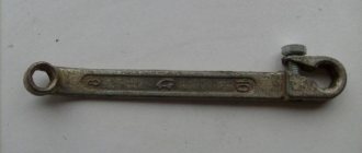
Handbrake drive VAZ 2110
Handbrake device VAZ 2110: 1 – lever fixation button; 2 – parking brake drive lever; 3 – protective cover; 4 – traction; 5 – cable equalizer; 6 – adjusting nut; 7 – lock nut; 8 – cable; 9 – cable sheath.
Brake fluid level sensor VAZ 2110
Design of the brake fluid reservoir cap of the VAZ 2110 with a level sensor: 1 – protective cap; 2 – sensor housing; 3 – sensor base; 4 – sealing ring; 5 – clamping ring; 6 – reflector; 7 – pusher; 8 – bushing; 9 – float; 10 – fixed contacts; 11 – moving contact.
Master cylinder with reservoir
1 – main cylinder body;
2 – low pressure sealing ring; 3 – drive piston of the “left front–right rear brake” circuit; 4 – spacer ring; 5 – high pressure sealing ring; 6 – pressure spring of the sealing ring; 7 – spring plate; 8 – piston return spring; 9 – washer; 10 – locking screw; 11 – drive piston of the “right front–left rear brake” circuit; 12 – connecting sleeve; 13 – tank; 14 – brake fluid emergency level sensor; A – clearance Master cylinder with sequential arrangement of pistons. A tank 13 is mounted on the master cylinder body, in the filler neck of which a sensor 14 for emergency brake fluid level is installed. The high pressure O-rings 5 and the rear wheel cylinder rings are interchangeable.
GTZ VAZ 2110 signs of malfunction, purpose of the device, performance check replacement
Despite the fact that these two units are inextricably linked with each other, in our material we will consider them separately. This will allow you to understand in detail all the nuances and features of the operation and repair of the two devices.
I – main cylinder body; 2 – low pressure sealing ring; 3 – drive piston of the “left front-right rear brake” circuit; 4 – spacer ring; 5 – high pressure sealing ring; 6 – pressure spring of the sealing ring;
7 – spring plate; 8 – piston return spring; 9 – washer; 10 – locking screw;
II – drive piston of the “right front-left rear brake” circuit; 12 – connecting sleeve; 13 – tank; 14 – brake fluid emergency level sensor; A – gap
Front wheel brake
1 – brake disc;
2 – pad guide; 3 – caliper; 4 – brake pads; 5 – cylinder; 6 – piston; 7 – pad wear indicator; 8 – sealing ring; 9 – protective cover of the guide pin; 10 – guide pin; 11 – protective casing The front wheel brake mechanism is disc, with automatic adjustment of the gap between the pads and the disc, with a floating caliper and a brake pad wear indicator. The bracket is formed by a caliper 3 and a wheel cylinder 5, which are tightened with bolts. The movable bracket is bolted to pins 10, which are installed in the holes of the guide 2 of the pads. Lubricant is placed in these holes, rubber covers 9 are installed between the pins and the pad guide. Brake pads 4 are pressed against the grooves of the guide by springs, the inner one of which has a lining wear indicator 7.
A piston 6 with a sealing ring 8 is installed in the cavity of the cylinder 5. Due to the elasticity of this ring, the optimal gap between the pads and the disk is maintained.
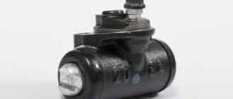
Wheel cylinder
1 – block stop;
2 – protective cap; 3 – cylinder body; 4 – piston; 5 – seal; 6 – support plate; 7 – spring; 8 – crackers; 9 – thrust ring; 10 – thrust screw; 11 – fitting; A – slot on the thrust ring The brake mechanism of the rear wheel (Fig. Brake mechanism of the rear wheel) is drum, with automatic adjustment of the gap between the shoes and the drum. The automatic clearance adjustment device is located in the wheel cylinder. Its main element is a split thrust ring 9 (Fig. Wheel cylinder), installed on the piston 4 between the shoulder of the thrust screw 10 and two nuts 8 with a gap of 1.25–1.65 mm.
The thrust rings 9 are inserted into the cylinder with tension, providing a shear force of the ring along the cylinder mirror of at least 343 N (35 kgf), which exceeds the force on the piston from tension springs 3 and 7 (see Fig. Brake mechanism of the rear wheel) of the brake pads.
When, due to wear of the linings, the gap of 1.25–1.65 mm is completely removed, the shoulder on the thrust screw 10 (see Fig. Wheel cylinder) is pressed against the shoulder of the ring 9, as a result of which the thrust ring moves after the piston by the amount of wear. When the braking stops, the pistons are moved by the force of the tension springs until the cracks stop against the shoulder of the thrust ring. This automatically maintains the optimal clearance between the pads and the drum.
Parking brake system drive
The mechanically actuated parking brake system acts on the brake mechanisms of the rear wheels. The parking brake drive consists of lever 2, adjusting rod 4, equalizer 5, cable 8, lever 10 (see Fig. Rear wheel brake mechanism), manual pad drive and expansion bar 8.
1 – protective cap; 2 – sensor housing; 3 – sensor base; 4 – sealing ring; 5 – clamping ring; 6 – reflector; 7 – pusher; 8 – bushing; 9 – float; 10 – fixed contacts; 11 – moving contact
Mechanical brake fluid emergency level sensor. The sensor body 2 with a seal 4 and the base 3 with a reflector 6 are pressed by a clamping ring 5 to the end of the tank neck.
A pusher 7 passes through the hole in the base, connected to the float 9 by means of a sleeve 8. There is a moving contact 11 on the pusher, and fixed contacts 10 are located on the sensor body. The contact cavity is sealed with a protective cap 1. When the level of brake fluid in the reservoir drops to the maximum permissible, the moveable the contact moves down onto the fixed contacts and closes the circuit of the hazard warning lamp on the instrument panel.
The principle of operation of the braking system
The operation of a hydraulic drive is based on the property of a liquid not to be compressed by external influences. Thanks to this, the liquid perfectly performs the role of a force transmitter without any losses, but provided that there is no gas in its composition.
The principle of operation of a hydraulic brake system is very simple: the driver presses the brake pedal, thereby beginning to act on the brake fluid located in sealed pipelines. Since it does not compress, the force leads to its movement through pipelines, the ends of which are connected to working mechanisms. Because of this, the pressure in the cavities of the mechanisms increases, and the pistons of the mechanisms come out of their seats, pressing the pads against the discs or drums - the movement slows down. When you stop pressing the pedal, the pressure drops (the fluid returns) and the pistons of the mechanisms return to their original position.
Video: How the braking system works
Device
Hydraulic brakes are installed on the machine and operate generally reliably. They are double-circuit and have a diagonal distribution. That is, if one part suddenly fails, then braking by another circuit is possible. For the sake of safety, the VAZ 2110 brakes operate diagonally, one circuit is the right front and left rear wheels, the other is also diagonal.
This device allows you to brake efficiently (without skidding and other troubles) even in the event of a malfunction, if the brakes in one of the circuits are lost.
Let's consider the design of the brake system. The hydraulic drive includes a vacuum booster, as well as a dual-circuit regulator that creates pressure in the rear brakes.
In addition, the hydraulic drive is equipped with pipelines divided into two circuits, hoses and brake mechanisms that provide braking to the front and rear mechanisms.
The hydraulic drive is activated by a pedal located in the cabin (middle). Here are the main components of the hydraulic drive:
- Vacuum booster.
It is designed in such a way that it creates pressure on the master cylinder piston, and thus causes braking; Vacuum brake booster - Pressure regulator drive.
It is through it that the working brake fluid flows to the rear brake mechanisms; Brake pressure regulator drive - The pressure regulator itself.
Already from the name it is clear that this device is responsible for the force of pressure, its decrease or increase. He does this depending on how loaded the rear axle of the car is; Pressure regulator - Main cylinder with pistons, equipped with a reservoir.
The filler neck of the tank is equipped with an emergency fuel level sensor; Master brake cylinder - Brake mechanism for the front wheel.
Its main parts are the disc, pads and wheel cylinders. The mechanism also provides an indicator to prevent complete wear and malfunction of the linings; Front wheel brake - Brake mechanism for the rear wheel.
Unlike the front disc brakes, the rear ones are drum brakes. This is the factory configuration. However, many car owners believe that their device does not provide high-quality braking, and change them to disc ones. Rear wheel brake
The brakes require attention. Without waiting for the warning light to come on, indicating a critical level of fuel fluid or wear of the linings, and even more so, without allowing the brakes to completely disappear, you need to carry out preventive checks.
Particular attention should be paid to all connections and hoses, since the “escaped” brake fluid will not make it possible to brake, and from here it’s not far from tragedy.
2110 brake design
A dual-circuit hydraulic system with a vacuum brake booster is not uncommon on cars developed in the 80s. Easy to maintain, without unnecessary electronic bells and whistles, like ABS, cheap spare parts and pads. The front brakes are disc, and on models 2112, in the hatchback body, they are also ventilated with a larger diameter. This is because on the twelfth only 16-valve engines were installed and more effective brakes were needed to stop this incredible hundred-horsepower power. And also in order to cope with the Opel engine of 150 horsepower, which was also sometimes used for modification by dozens.
The rear brakes are tens of drum type, and the parking brake is mechanical. Everything is like in the good old classics. The car has a vacuum brake booster and the system is divided into two circuits. If one of them fails, the second one remains operational, so there won’t be a dozen left without brakes. The circuits work in a diagonal pattern - front-rear wheel diagonally. Also, the brake system of the VAZ 2110, the diagram of which is presented above, has a pressure regulator for uniform distribution of braking force, depending on the load of the rear axle. Both brake circuits are connected through the regulator.
Alarm Signals
The following symptoms are quite unsafe, please note:
- If the brakes are completely gone, then it’s clear that you can’t go any further, even to a service station! If independent repairs on site are beyond your capabilities, or simply impossible, you need to call a tow truck;
- When braking there is a strong vibration, especially felt in the steering column. You press the pedal, and it’s just hard to hold the steering wheel in your hands. There can be several reasons for vibration: • Many argue that vibration can occur due to the fact that there are non-ventilated disks. Their design is such that they really don’t like it when braking occurs in the rain, or even right in a puddle. No repair will help here - you need to replace the disks with ventilated ones; • Vibration may also occur if there is a problem with the rear drums. If upon inspection you find dark spots on the working surface, this indicates uneven wear. The vibration is usually very strong. Such drums need urgent repairs, and possibly replacement with disc brakes; • Check the front brake discs for deformation. At the same time, vibration is also observed.
- The brake pedal is too tight. There may also be several reasons for this: • A clogged air filter for the vacuum booster can cause the pedal to become stiff; • Check the vacuum booster itself. Its possible malfunctions are destruction of the diaphragm, tip, sticking of the check valve, damage to the hose connecting the intake manifold to the amplifier. In all these cases, a stiff pedal syndrome may occur, and repair of any of the indicated faults is necessary; • Also, the pedal may become stiffer as the pads wear, check them too.
- Hisses when you press the brake. If it hisses exactly when you press the pedal, you need to urgently check the vacuum booster, and then decide whether it needs repair or replacement. But if it hisses when you release the brake, then this is a normal phenomenon. Unless, of course, the hiss is too obvious.