Battery disconnect switches became quite widespread about 40 years ago. They were installed on Soviet and imported cars.
The switch had 2 main tasks. This is the organization of a rather simple but effective anti-theft system, as well as protection against current leakage while the vehicle is parked.
Currently, the tasks facing such devices have not changed. At the same time, many motorists continue to be interested in the possibility of installation.
KOMITART - entertainment and educational portal
Sections of the site
- " To home
- » Radio amateur
- » APEX AUDIO
- " Power supplies
- » Guitar accessories
- » Do it yourself
- » For motorists
- » Service-Manual
- » PREAMPLIFIERS
- » Free programs
- " Computer
- » Books
- " Women things
- We cook deliciously and quickly
- » Games on the site
- " Humor
- » Miscellaneous - interesting
DirectAdvert NEWS
GNEZDO NEWS
friends of site
Statistics
Pay attention to technological nuances
A good switch is equipped with fuses and serves to de-energize the car battery. It is this circumstance that poses an additional problem for potential hijackers. If you decide to purchase a power switch, make sure it is new. Don't use a used one! In this state, the VM will easily damage the electrical system of the machine.
When the battery is de-energized, there is a high probability that the car computer will turn off. This, in turn, threatens failures, such as erasing from memory information necessary for full operation. How to prevent such a development of events, what energy source to buy and how to connect it - these issues should be discussed with professionals.
Read more: All-wheel drive on the Tiguan
A simple circuit of a ground switch for a car.
A simple circuit of a ground switch for a car.
How to make a ground switch for a car yourself
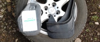
Many motorists, when parking their car for a long time, want to disconnect the battery from the on-board network, and in order not to constantly remove the terminals, they independently install all kinds of mechanical switches in the engine compartment, because such switches are not provided in serial passenger cars.
The contacts of mechanical switches must be designed to carry a current of several hundred amperes and have a very low transition resistance, so the use of conventional network switches or toggle switches in this situation is not acceptable. For these purposes, there are special car mass switches, for example, VK-318, or in some articles found on websites, the RAD-1 remote mass switch device is mentioned, although we were unable to find information on the RAD on the Internet. (Maybe, of course, we were looking in the wrong place, but still...).
The circuit that we want to propose does not have mechanical contacts, and its main advantage is that this mass switch can be controlled remotely using a small toggle switch or a button with fixed positions, installed in any place convenient for you. It can be installed inside the car, and in order to turn off the mass it is not necessary to open the hood lid.
This diagram was published a long time ago in one of the radio engineering magazines, so we will not reinvent the wheel and redraw it in our own way, it is quite informative and intelligible, so we are posting a scan of the circuit diagram in the original as is without changes.
The figure shows that a powerful thyristor and diode are installed on an aluminum corner with dimensions indicated. On the vertical side (as shown in the picture) there is a hole through which it is attached in the engine compartment to the car body, not very far from the battery.
The thyristor works like a key; when the toggle switch is turned on, it will be open. But there is one “but”... As you know, a thyristor can pass current only in one direction (from the anode to the cathode), and in order for the battery to receive recharging from the generator while driving, a diode with the opposite polarity is installed in parallel with the thyristor.
Attaching the angle to the car body must have good electrical contact, and the wire connecting the thyristor to the tip must have a fairly impressive cross-section; you can use the one that connects the negative terminal of the battery to the car body; otherwise, there are no critical requirements. Some craftsmen advise placing the device in a metal box and painting it in the color of the car body.
The parameters of some powerful thyristors are shown in the following image, to enlarge which click on the picture.
The parameters of silicon diffusion diodes of the D2XX series are given below:
Parameters of silicon diffusion diodes of the D2XX series
Varieties
There are several options for used mass switches.
They are:
- thyristor;
- manual;
- remote electromechanical (relay-based).
Manual devices are mainly used on trucks and special equipment. Such systems can operate under conditions of high currents of up to 1000 A. They are also successfully used in passenger cars.
The most convenient disconnectors are those that are located on the battery terminals and are intended specifically for passenger cars. The remote type of switch can be installed on trucks and passenger cars. Control is carried out from the cabin using a special hidden button.
Powerful thyristors rated at 160-320 A are also suitable for passenger cars. The control can also be hidden. But thyristors do not always withstand high currents when starting an internal combustion engine.
Installing the mains switch
Battery main switch (“mass switch”). Should be located as close to the battery as possible. If a switch is used with only one pole (only one wire opens), then the switch must be installed on the power wire (“positive” wire) regardless of the date of manufacture of the vehicle (clause 9.2.2.8.1 of ADR).
The main battery switch must have an enclosure (attention! this requirement does not apply to the protective casing, but to the direct enclosure (housing) of the main switch itself) with protection degree IP 65 (complete protection from dust and protection from strong jets of water from any direction) in accordance with standard IEC 60529. Compliance with the requirements of the IEC standard is confirmed by markings applied directly to the switch body.
The connection point of the electrical cable at the main switch contacts must have degree of protection IP 54 ( partial protection against dust and protection against splashing water from any direction). This means that the contacts cannot be exposed . However, this degree of protection is not required if the contacts are enclosed in a shell, which may be an additional switch casing or a battery container; in the latter case (battery container), the contacts can simply be insulated, for example, with rubber caps. (clause 9.2.2.8.5 ADR)
The control device (key, switch control button) must be installed in the vehicle cabin in a place accessible to the driver and be clearly marked. It must be protected against accidental operation by means of a protective cover, double switch or other suitable means. (clause 9.2.2.8.2 ADR). Typically, a toggle switch with a cover, two buttons that must be pressed simultaneously, a rotary toggle switch with locking, etc. are used as a control device.
If the remote control device (toggle switch) is electrically operated, the electrical circuits of this device must be protected by a fuse or circuit breaker or safety barrier located as close as possible to the power source. (clause 9.2.2.8.2, in accordance with 9.2.2.9.1 (c) ADR).
Malfunction or dismantling of the main battery switch and its remote control device in cases where their presence is mandatory is unacceptable. (20.14.15 Appendix No. 8 TR CU) Applies to all categories of vehicles transporting dangerous goods, including PACKED, BULK and TANK
What else is important to know?
If you decide to install such a scheme, you should first consider several important points.
- If there are devices and instruments in the car that require adjustment, in the event of a power failure, they will need to be periodically restored. This usually concerns setting the time, date, etc.
- Opening the ground does not reset the odometer and does not reset the ECU settings, so there is no need to worry about this.
- If your alarm system has an autonomous siren, it may be triggered in the event of a ground fault.
- If the alarm does not have an autonomous power source, disconnecting the battery leads to automatic deactivation of the security system. It just won't work.
- On vehicles with an injection type engine, if the ground is disconnected, the power to the controller is also turned off. This leads to the deletion of all accumulated information.
- Periodically check the condition of the contacts and take resistance measurements. It is better to lubricate them with lithol, and also renew the lubricant.
- Some experts agree that it is better not to use the switch for cars manufactured after 2000. If it accidentally operates while the ignition is on, the immobilizer may become unstuck. The motorist will lose the ability to access his own car. To restore work, you need the help of specialists and an impressive amount of money.
- Disabling the mass leads to the loss of previously made settings in the multimedia system.
All this directly indicates that not everyone needs a mass switch and not always. And if you use it, then only when absolutely necessary.
Think carefully about the feasibility and necessity of using a car battery disconnect switch. Sometimes it makes sense to make a device yourself. But most are of the opinion that it is better to use factory solutions and involve experienced auto electricians. The choice is yours.
Scheme of remote vehicle ground switch
In [1] there was a description of an electronic ground switch for a car battery. However, in my opinion, the main disadvantage of this switch is that it cannot be used if a short circuit occurs in the on-board network. In addition, the ground switch does not have an on indicator. But this is often necessary.
I offer my circuit for an electronic ground switch (VM). The device is turned on and off using two buttons. A simplified VM diagram is shown in Fig. 1, and a complete diagram is shown in Fig. 2. Introduced into it
filter for high-voltage interference resulting from the operation of the generator and ignition. The filter is assembled on elements C1, C2 and VD1. Capacitors C1 and C2 suppress voltage ripples in the generator rectifier, and the zener diode VD1 (with a stabilization voltage of 18 V) eliminates voltage surges that occur in the vehicle’s on-board network during operation of the ignition system and electric motors. The VM has two sockets for connecting IR remote control and alarms triggered by various sensors (door switches, swing sensor, etc.).
Capacitors SZ. C5 - spark extinguishing. They are designed to eliminate sparking of relay contacts and push-button switches. Diode VD3 is also designed to eliminate sparking of the contacts of the SB2 button, which appears as a result of the self-induction EMF of the relay winding K1.
The power part of the device is assembled on elements VD2 and VS1. The battery charge current flows through the diode VD2, and the discharge current flows through the thyristor VS1.
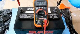
Basic parameters of the VM (when using radioelements indicated in the diagram):
Operating voltage: - maximum, V. 16.6 - minimum, V. 10.5 Current consumption (own) - in the on state, A. 0.12 - in the off state, mA. 15 Reverse current, mA, no more. 15 Direct, maximum permissible current: - charging, A. 80-bit, A. 160 Voltage drop on the circuit (between terminal + battery and ground), V, no more. 0.25 Maximum permissible pulse voltage, V. 200
Let's consider the operation of the device.
When the contacts of the SB1 button are closed, relay K1 is activated and self-blocking with its contacts K1.2. At the same time, contacts K1.1 close, which causes the thyristor VS2 to open. It, in turn, turns on the thyristor VS1. Thyristor VS1 connects the battery to the car body, which causes LED HL1 to light.
When you press the SB2 button, the current through the coil of relay K1 is interrupted and its contacts open. At the same time, the anodes and cathodes of the thyristors are closed, which causes their forced
closing. The device actually does not need to be set up. But a situation is possible when the vehicle’s “mass” will not turn off. Then you will have to reduce the resistance of resistor R2 to 6 Ohms, and perhaps swap the groups of contacts of the SB2 button.
The device is not critical to details. Instead of thyristor VS1, you can use any powerful thyristor, designed for a maximum forward current of at least 160 A and a reverse voltage of at least 200 V. Any diode with a current of at least 35 A and rev>200 V is suitable as VD2. In addition, it is necessary that The diode's cathode was connected to the body. Diodes VD3, VD4 can be replaced with D226A (B, C, D) Zener diode D817D - with any other one with UCT=14. 20 V and 1STmax^400 mA - Resistor R2 should be a wirewound, and R3 should be designed for a power dissipation of 1.2 W.
Relay K1 is suitable for any relay that has four groups of switching contacts, an operating voltage of 9.11 V and holding contacts when the voltage drops to 5.6 V.
Tips and tricks
How to install PTF on a VAZ 2114 and change the light bulbs in them
Here are the basic recommendations for correctly installing the main switch:
- if there are electronic devices in the car (all new cars now have them) that require adjustment, after turning off the mass, you will have to re-set the time and other settings;
- if the security system design has an autonomous siren, then the siren turns on and starts making a sound when the “mass” is turned off;
- if the car alarm design does not have an autonomous siren, then after turning off the mass of the car, the entire security system of the car is also turned off;
- When the mass is turned off in injection cars, the controller is turned off, in which all accumulated information is erased.
After some time, depending on operating conditions (in particular, high humidity), the contacts of the device undergo corrosion, which leads to an increase in current resistance. Transient high resistance is sensitive for a conventional or gear starter, so it is advisable to lubricate the contacts with lithol or special petroleum jelly.
Scheme of remote vehicle ground switch
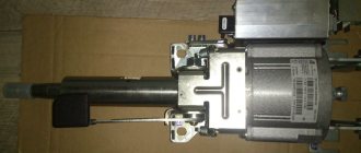
LiAZ-5256. REMOTE BATTERY SWITCH
Remote switch for batteries (“ground”) type 1420.3737 or VK860-B
designed to disconnect batteries from the bus power supply network during long-term parking and in emergency situations. At the same time, the power supply to some consumers connected via a two-wire circuit is not disconnected when the batteries are disconnected from ground. The lower side lights, direction indicator lights, hazard warning lights and emergency switch, electro-pneumatic door control valves, liquid heater, and portable lamp sockets do not turn off. If you need to completely disconnect, you need to remove the positive terminal of the battery.
The design of the VK860-B switch is described below (Fig. 16-5).
The remote switch consists of an electromagnet, a housing with a contact part and a manual activation device protected by a cover. When power is supplied to the winding 3 of the electromagnet, the armature 4 and the rod 5 screwed into it transmit force to the rod 6 of the contact device, which moves downwards. The latch 7, falling into the recess of the lever 8 with a special profile, sitting on the axis 9, fixes the switch contacts in the closed position. In this case, the springs 10 are compressed.
The next time power is applied to the winding 3 of the electromagnet, the rod 5 transmits force to the lever 8, which, turning around its axis, recesses the latch 7 in the rod 6, and the movable contacts 13, under the action of the springs 10, open the circuit, moving to the original fixed position. In this case, the latch 7 takes a different stable position.
The current switch is located on the left panel of the battery compartment.
Control of switch 1 (Fig. 16-6) - remote via relay K4 in block 12, from two
push-button switches, one of which 13 is located on the instrument panel in the cockpit, and the other 14 is located on the panel in the engine compartment. There is a warning lamp on the instrument panel (in switch button 13 or on the speedometer scale), indicating that the batteries are connected to the bus's power supply network. It is possible to turn off the “mass” only when the devices are turned off by switch 6 in the engine compartment (the warning lamp of the lamp 7 is not lit), otherwise there is a special lock in the control system - a short-circuit relay in block 12. It is possible to disconnect the batteries regardless of the position of the switch 6 of the devices by turning the emergency lever switch 11 to the second non-locking position, for which relay K5 is used in block 12.
In the event of a failure of the remote control system for the switch, the ground can be turned off manually by pressing the button located directly on the electromagnet of switch 1 under the protective cover.
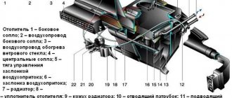
Rice. 16-5. Remote switch for batteries (“ground”) type VK860-B: 1 — manual control button; 2 — protective cover; 3 - electromagnet winding; 4 — electromagnet armature; 5 — electromagnet rod; 6 — contact device rod; 7 — clamp; 8 — lever; 9 - axis; 10 — springs; 11, 12 — contact bolts; 13 - moving contacts
Rice. 16-6. Control circuit for the remote switch of batteries ("ground"): I - remote switch 1420.3737 or VK860-B of batteries ("ground") (in the battery compartment); 2, 3 — 6CT-190TP batteries; 4 — ammeter shunt 75 ShS-50-0.5 (on the rear distribution board); 5 — thermobimetallic fuse 292.3722 (on the engine compartment panel, push-button); 6 — switch 4602.3710 for instruments in the engine compartment; 7 — lamp 124.3803 of the control lamp for turning on the instruments (on the engine compartment panel); 8 — fuse block 11.3722 (on the engine compartment panel); 9 — thermobimetallic fuse 292.3722 (on the fuse panel in the cabin, push-button, rear); 10 — instrument and starter switch 2101.3704 (“lock”); II - emergency switch VK354-01; 12 — power supply control unit 553.3747 (on the rear distribution board, front unit): short-circuit relay 11.3747.010-21; K4, K5 - relay 11.3747.010-11; 13 — switch 3842.3710-08.39 with a control lamp (green) (control of the remote “mass” switch from the cab); 14 — switch VK322 (control of the remote “ground” switch from the engine compartment)
Terminal care
To maintain battery terminals in working condition, it is necessary to take proper care of them in a timely manner. To do this, do the following:
- Remove the battery;
- Prepare a strong solution of baking soda. The terminals are lowered into it. You should keep them in the solution for about 5 minutes. During this time, bubbles can be seen rising from the metal. The terminals are removed when the bubbles stop flowing;
- The removed terminals are inspected; they should not be severely damaged by corrosion. Wipe the terminals;
- Apply special lubricant or technical petroleum jelly to the contact points.
Prevention should be carried out at least 2 times a year. Experienced motorists recommend doing this in spring and autumn. Article on the topic “How to lubricate battery terminals.”
LiveInternetLiveInternet
- Registration
- Entrance
—Applications
- All (7)
- Postcards
Reborn catalog of postcards for all occasions - Wall Wall
: mini-guest book, allows visitors to your diary to leave messages for you. In order for messages to appear on your profile, you need to go to your wall and click the “Update” button - always no analogues at hand
^_^ Allows you to insert a panel with an arbitrary Html code into your profile. You can place banners, counters, etc. there - Play your music
84 channels of radio streaming with theme music. Choose your music and listen - Music player
Tips and tricks
Here are the basic recommendations for correctly installing the main switch:
- if there are electronic devices in the car (all new cars now have them) that require adjustment, after turning off the mass, you will have to re-set the time and other settings;
- if the security system design has an autonomous siren, then the siren turns on and starts making a sound when the “mass” is turned off;
- if the car alarm design does not have an autonomous siren, then after turning off the mass of the car, the entire security system of the car is also turned off;
- When the mass is turned off in injection cars, the controller is turned off, in which all accumulated information is erased.
After some time, depending on operating conditions (in particular, high humidity), the contacts of the device undergo corrosion, which leads to an increase in current resistance. Transient high resistance is sensitive for a conventional or gear starter, so it is advisable to lubricate the contacts with lithol or special petroleum jelly.
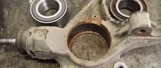
PROBLEMS WITH MASS WIRE
The studs for fastening the common wires are often painted along with the body, and therefore the contact on them is not always reliable. In addition, they are fastened at the factory through a nut - first the nut is screwed onto the stud, then the minus is installed, and only then the wires are attracted to ground with another nut. The bottom nut is often poorly tightened, which is why electrical problems arise.
Often, mass-produced studs rust and the integrity of the contact is compromised.
It is a good idea to place a castle washer between the bottom nut and the body on the stud. The washer will have reliable contact with the body, and electrical problems will not arise due to poor mass.
Castle nut is a good option for connection
Video
In this video, the skillful hands of experienced drivers make a button for remotely switching off the car's weight with their own hands.
Tips and recommendations on how to choose a weight for a car.
This video shows the choice of location, how to install and connect the button from a Kamaz car to a Mercedes car.
And this is for those who want to do it completely with their own hands.
There are several ways to create a mass switch. Anyone who bought mass buttons or made them themselves, write in the comments.
0
Author of the publication
offline 1 month
Long-term parking: what to remove and is it possible to disconnect one terminal
The battery is hard-wired to the car network. When the ignition is turned off, all consumers still do not turn off. The radio, alarm, and on-board computer take energy from the battery. In a few days, the battery will not be able to discharge. And after a month or more, the charge drops to such an extent that at least a recharge is needed.
To prevent the battery from draining, you need to disconnect the battery. The question arises, which terminal to remove from the battery when parked for a long time.
It would be more correct to remove both terminals on the battery, then it will be isolated from the effects of the car’s electrical equipment.
You can also remove the positive one, but then the car’s network will turn off. The weight of the body will affect the negative terminal, which will lead to faster self-discharge.
How to make your own VMA
How to connect an LED switch: rules for connecting an illuminated switch
According to the type of action, the mains switch can be mechanical (triggered by screwing in/unscrewing a screw, which is a circuit closure) or electrical, actuated by pressing a button or key.
VMAs are also distinguished by the method of installation: there are open-type devices, as well as switches with hidden installation.
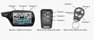
Classification of power switches by initiation method: manual (tactile pressing with fingers) and remote (switching off using a key fob). Most of the models presented in the retail chain are electric, activated by a combination of buttons located on the dashboard or in any other place accessible to the driver.
The instructions for such devices indicate which key combination should be used to break or turn on the circuit. This VMA can be used as an anti-theft agent.
Here is a diagram of the simplest ground switch.
It should be noted that the very procedure of turning off the mass on some cars is fraught with various consequences, such as resetting to zero some parameters stored in volatile memory. Moreover, in the latest generation of premium-level cars, even a short-term shutdown of the on-board power supply is a serious violation of the vehicle operating rules.
For those car enthusiasts who prefer to do everything themselves, we will describe another simple scheme for manufacturing a VMA.
It does not provide for the presence of mechanical contacts, being completely electronic. Thus, with the help of this device it will be possible not only to disconnect the battery mass, but also to use it as an anti-theft agent.
The device circuit includes two main components: an SCR and a diode.
The role of the thyristor in this circuit is to perform the function of an electronic relay, the turning off/on of which depends on the appearance of electrical pulses on the control electrode.
The S41 shutdown button, if you want to use the device as an anti-theft device, should be mounted in a hidden place. When the contacts are closed, an initiating pulse appears in the circuit, which, upon reaching the trinistor, unlocks it. As a result, the resistance of the semiconductor device drops and the circuit closes.
How can I make sure that the battery still has the ability to replenish its charge from the generator? It is for this purpose that a diode is provided in the circuit, which is connected to the thyristor in parallel. In the figure, both parts are mounted on a duralumin plate or angle; stranded wires, preferably copper, should be used to connect the components.
Preparing to disconnect the battery
Although the removal and installation procedure is a completely familiar process for all car enthusiasts, you should pay attention to safety rules, how to properly remove the terminals from the battery, in what sequence, how to disconnect the battery so as not to harm the car
Necessary equipment
If you know which wire to remove from the battery first, disconnecting is not a difficult process, provided you follow certain rules:
- remove the battery cover;
- Use a metal brush to remove accumulated dust;
- determine which key is needed to remove the terminal;
- prepare a screwdriver, a set of keys, usually they are 8, 10 or 13 mm in size.
Safety precautions
It is better to wear gloves when disconnecting the battery. When removing a battery, an experienced driver should always know which terminal to remove first and how to remove the terminals from the battery in order to comply with safety precautions. The vents release hydrogen, which is explosive. A small spark from a short circuit can cause an explosion. It is better to carry out the removal work outdoors or in a ventilated area.
Before turning off the device, you need to carry out a number of mandatory procedures:
- turn off the ignition;
- guaranteed to turn off all electronics;
- close the windows and doors, if the device is located in the trunk, close the hood;
- turn off the mains switch, if there is one;
- decide which terminal should be removed from the battery first;
- when contacts are oxidized, do not hit them with pliers or a hammer, otherwise the plates will be destroyed;
- remove the terminal from the battery with negative polarity, in this case it is necessary to position the negative wire with the connector in such a way that it does not dangle, does not interfere with further actions and cannot return to its original place;
- remove the positive connector;
- After removing the battery, do not throw or hit the battery to avoid liquid leakage inside;
- The removed device cannot be stored at low temperatures so that the plates do not fall off.
The procedure for removing battery terminals for foreign cars is the same as for domestic cars.