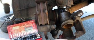
The domestic car VAZ 2110 is equipped with a brake system with separated diagonal contours, which ensures high operational safety. The first type of circuit is aimed at operating the front right and rear left brake devices.
The second type circuit provides the operation of the front left and rear right devices. The presence of two circuits makes it possible to replace them in the event of failure of one of them.
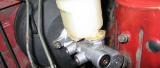
If the system's efficiency drops sharply, this most often indicates a malfunctioning brake master cylinder. To correct the situation, you need to repair or replace a component such as the master cylinder.
In order to carry out the work correctly and not make mistakes, you need to understand the operation of the car’s braking system. You can read more about it here:
Why do the brakes disappear in the VAZ-2110?
If the brakes on a VAZ-2110 leave much to be desired, you should not blame the head cylinder (GTC) immediately, especially since there are several additional reasons for mechanism failures:
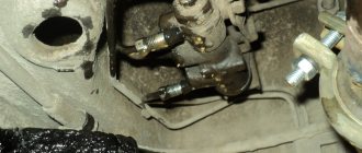
- The working cylinder is leaking; this process can occur gradually or quickly.
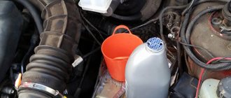
- Look at how much brake fluid is in the reservoir. The brake line may have broken, causing fluid to leak.
- The same thing sometimes happens with rubber hoses. They can rot or break through.
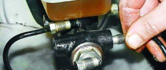
In fact, determining whether the master cylinder is to blame for brake failure or not is simple - examine its appearance. If there are traces of leaks, then your fears are not in vain.
Also pay attention to the following signs of a gas turbine engine malfunction:
- The brake pedal remains in the same position when pressed and applied.
- Alternatively, it moves idle, that is, nothing changes in the operation of the brakes.
Pressure regulator
1 – pressure regulator housing; 2 – piston; 3 – protective cap; 4, 8 – retaining rings; 5 – piston sleeve; 6 – piston spring; 7 – body bushing; 9, 22 – support washers; 10 – sealing rings of the pusher; 11 – support plate; 12 – pusher bushing spring; 13 – valve seat sealing ring; 14 – valve seat; 15 – sealing gasket; 16 – plug; 17 – valve spring; 18 – valve; 19 – pusher bushing; 20 – pusher; 21 – piston head seal; 23 – piston rod seal; 24 – plug; A, D – chambers connected to the main cylinder; B, C – chambers connected to the wheel cylinders of the rear brakes; K, M, N – gaps
The pressure regulator regulates the pressure in the hydraulic drive of the rear wheel brakes depending on the load on the rear axle of the vehicle. It is included in both circuits of the brake system and through it brake fluid flows to both rear brake mechanisms.
Pressure regulator 1 (Fig. Pressure regulator drive) is attached to bracket 9 with two bolts 2 and 16. At the same time, front bolt 2 simultaneously secures fork bracket 3 of lever 5 of the pressure regulator drive. A double-arm lever 5 is hinged on the pin of this bracket with a pin 4. Its upper arm is connected to an elastic lever 10, the other end of which is pivotally connected to the rear suspension arm bracket through an earring 11.
Bracket 3 together with lever 5 can be moved relative to the pressure regulator due to the oval holes for the fastening bolt. This regulates the force with which lever 5 acts on the regulator piston (see subsection 6.4.2). The regulator has four chambers: A and D (Fig. Pressure regulator) are connected to the main cylinder, B to the left, and C to the right wheel cylinders of the rear brakes.
In the initial position of the brake pedal, piston 2 (see Fig. Pressure regulator) is pressed by lever 5 (see Fig. Pressure regulator drive) through leaf spring 7 to pusher 20 (see Fig. Pressure regulator), which is pressed against the saddle under this force 14 of valve 18. In this case, valve 18 is pressed away from the seat and a gap H is formed, as well as a gap K between the piston head and seal 21. Through these gaps, chambers A and D communicate with chambers B and C.
When you press the brake pedal, fluid flows through gaps K and H and chambers B and C into the wheel cylinders of the brake mechanisms. As the fluid pressure increases, the force on the piston increases, tending to push it out of the housing. When the force from the liquid pressure exceeds the force from the elastic lever, the piston begins to move out of the body, and after it, under the action of springs 12 and 17, the pusher 20 moves together with the sleeve 19 and rings 10. In this case, the gap M increases, and the gaps H and K decrease . When the gap H is completely selected and the valve 18 isolates chamber D from chamber C, the pusher 20, together with the parts located on it, stops moving after the piston. Now the pressure in chamber C will vary depending on the pressure in chamber B. With a further increase in the force on the brake pedal, the pressure in chambers D, B and A increases, piston 2 continues to move out of the body, and sleeve 19 together with o-rings 10 and plate 11 under increasing pressure in chamber B, it shifts towards plug 16. At the same time, the gap M begins to decrease. Due to the decrease in the volume of chamber C, the pressure in it, and therefore in the brake drive, increases and will be practically equal to the pressure in chamber B. When the gap K becomes zero, the pressure in chamber B, and therefore in chamber C, will increase less degree than the pressure in chamber A due to throttling of the liquid between the piston head and seal 21. The relationship between the pressure in chambers B and A is determined by the ratio of the difference in the areas of the head and piston rod to the area of the head.
As the vehicle load increases, the elastic lever 10 (see Fig. Pressure regulator drive) is loaded more and the force from lever 5 on the piston increases, that is, the moment of contact between the piston head and seal 21 (see Fig. Pressure regulator) is achieved at greater pressure in the main brake cylinder. Thus, the effectiveness of the rear brakes increases with increasing load.
If the brake circuit “left front – right rear brake” fails, the o-rings 10, bushing 19, under the fluid pressure in chamber B, will move towards the plug 16 until the plate 11 rests on the seat 14. The pressure in the rear brake will be regulated by part of the regulator, which includes piston 2 with seal 21 and bushing 7. The operation of this part of the regulator, in the event of a failure of the said circuit, is similar to the operation with a working system. The nature of the change in pressure at the outlet of the regulator is the same as with a working system.
If the brake circuit “right front – left rear brake” fails, the pressure of the brake fluid forces the pusher 20 with the bushing 19 and sealing rings 10 toward the piston, pushing it out of the housing. The M gap increases and the H gap decreases. When valve 18 touches seat 14, the increase in pressure in chamber C stops, that is, the regulator in this case works as a pressure limiter. However, the achieved pressure is sufficient for reliable operation of the rear brake.
There is a hole in housing 1, closed by plug 24. Liquid leakage from under the plug when it is squeezed out indicates a leak in rings 10.
Is it always possible to repair the GTZ?
The main brake cylinder of the VAZ-2110 can indeed be repaired, but not always, so when starting repairs, keep the following features in focus:
- It is impossible to repair the part without a repair kit created specifically for repairing the VAZ-2110.
- It is impossible to repair the damage if there are scratches on the interior mirror.
Drivers believe that repairs are a more profitable undertaking than buying a new mechanism for restoring the brakes of a VAZ-2110. Although experts do not agree with this, explaining: if a part breaks once, another repair is not far off, and so on ad infinitum. That’s why it doesn’t hurt to gain knowledge of what it looks like to replace the master brake cylinder of a VAZ-2110 with your own hands in a garage.
Diagnostics and repair
From the signs listed above, it is easy to understand that in most cases there is only one source of problems - rubber products that have become unusable. The cuffs crack and swell, as a result they leak liquid and close the discharge holes. Hence the recommendation: all “rubber bands” of the brake system should be changed at intervals of approximately 100 thousand km, without waiting for critical wear.
Reference. Many auto mechanics express the opinion that after replacing the cuffs, the main hydraulic cylinder will not last long. The statement is true if the car owner purchased cheap, low-quality spare parts or installed new o-rings in the cylinder, where internal wear has formed in the walls.
Before checking the GTZ for operability, make sure there are no other faults:
- Inspect the wheel assemblies from the inside for leakage of brake fluid from the working cylinders.
- Check the integrity of the expansion tank and the fluid level in it.
- Start the engine and at idle speed, press the vacuum take-off pipe to the amplifier. If the engine speed has increased noticeably, there is an air leak and the master cylinder is most likely working.
List of required tools
Repairing a car is not as difficult as it seems; special tools will come to the rescue:
- screwdriver with flat and Phillips tips;
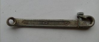
- key designed for 10, 17 dimensions;
- container filled with brake fluid - ½ liter is enough;
- brake fluid;
- ordinary medical syringe.
When replacing a part yourself, you need to enlist the help of a friend who can periodically press the brake pedal.
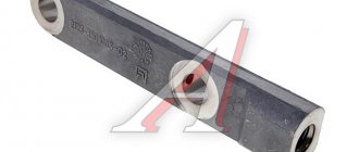
Parking brake system drive
The mechanically actuated parking brake system acts on the brake mechanisms of the rear wheels. The parking brake drive consists of lever 2, adjusting rod 4, equalizer 5, cable 8, lever 10 (see Fig. Rear wheel brake mechanism), manual pad drive and expansion bar 8.
1 – protective cap; 2 – sensor housing; 3 – sensor base; 4 – sealing ring; 5 – clamping ring; 6 – reflector; 7 – pusher; 8 – bushing; 9 – float; 10 – fixed contacts; 11 – moving contact
Mechanical brake fluid emergency level sensor. The sensor body 2 with a seal 4 and the base 3 with a reflector 6 are pressed by a clamping ring 5 to the end of the tank neck.
A pusher 7 passes through the hole in the base, connected to the float 9 by means of a sleeve 8. There is a moving contact 11 on the pusher, and fixed contacts 10 are located on the sensor body. The contact cavity is sealed with a protective cap 1. When the level of brake fluid in the reservoir drops to the maximum permissible, the moveable the contact moves down onto the fixed contacts and closes the circuit of the hazard warning lamp on the instrument panel.
General information about electrical equipment of VAZ 2110, 2112, 21102
Steering VAZ 2110 (2112)
How to remove an old VAZ-2110 cylinder
Replacing the master brake cylinder of a VAZ-2110 involves first removing the old model. The subsequent installation of the new model depends on how well this process goes. To avoid mistakes and miscalculations, follow these instructions:
- Disconnect the brake fluid indicator related to the GTZ from the expansion tank located in the VAZ-2110.
- Unscrew the closing valve of the expansion tank.
- Using a syringe, pump out the liquid, and then unscrew the pipeline from the general brake system.
- If you have a 10 key, disconnect 4 tubes, 2 on each side.
- Gently push the tubes to the side so that they do not interfere with the removal of the cylinder.
- Next, your task is to get to the bolts that secure the part to the vacuum brake booster. To do this, unscrew the screws using a Phillips head screwdriver. These screws are responsible for holding and securing the engine compartment upholstery.
- Bend the upholstery material and 2 nuts will become available to you.
- Remove the GTZ by removing it from the studs directly with the tank.
- If the tank also needs to be replaced, then the old sample is slightly pryed with a screwdriver and removed, and a new one is put in its place.
Wheel cylinder
1 – block stop; 2 – protective cap; 3 – cylinder body; 4 – piston; 5 – seal; 6 – support plate; 7 – spring; 8 – crackers; 9 – thrust ring; 10 – thrust screw; 11 – fitting; A – slot on the thrust ring
The rear wheel brake mechanism (Fig. Rear wheel brake mechanism) is drum-type, with automatic adjustment of the gap between the shoes and the drum. The automatic clearance adjustment device is located in the wheel cylinder. Its main element is a split thrust ring 9 (Fig. Wheel cylinder), installed on the piston 4 between the shoulder of the thrust screw 10 and two nuts 8 with a gap of 1.25–1.65 mm.
The thrust rings 9 are inserted into the cylinder with tension, providing a shear force of the ring along the cylinder mirror of at least 343 N (35 kgf), which exceeds the force on the piston from tension springs 3 and 7 (see Fig. Brake mechanism of the rear wheel) of the brake pads.
When, due to wear of the linings, the gap of 1.25–1.65 mm is completely removed, the shoulder on the thrust screw 10 (see Fig. Wheel cylinder) is pressed against the shoulder of the ring 9, as a result of which the thrust ring moves after the piston by the amount of wear. When the braking stops, the pistons are moved by the force of the tension springs until the cracks stop against the shoulder of the thrust ring. This automatically maintains the optimal clearance between the pads and the drum.
Installation of a new VAZ-2110 cylinder
Features of installing brake parts are included in the following list:
- If there is a need to replace the tank, this must be done before installing the cylinder.
- To install the master cylinder, follow the reverse order of the instructions for removing the defective attachment.
What does the cylinder installation look like:
- Try to get the pusher rod into the hole located on the master cylinder.
- Then slide onto the 2 studs, tightening the mounting nuts tightly with a 17mm wrench.
- All that remains is to connect the pipeline tubes, but do not tighten them too tightly.
- Open the reservoir cap and pour brake fluid inside.
- Place the engine compartment trim in its original place and secure the result with self-tapping screws. At this point, the replacement of the VAZ-2110 master brake cylinder can be considered successfully completed.
- Now it’s time to properly bleed the system - put your partner in the car, make a couple of pedal strokes, press and release some brake fluid along with the air. The goal is to ensure that there are no air bubbles when opening the fitting.
Video instructions for installing a new part to replace the old one on a VAZ car can be viewed below:
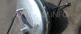
Vacuum booster
1 – vacuum booster housing;
2 – amplifier housing cup; 3 – rod; 4 – adjusting bolt; 5 – rod seal; 6 – sealing ring of the master cylinder flange; 7 – diaphragm return spring; 8 – amplifier pin; 9 – tip mounting flange; 10 – valve; 11 – hose tip; 12 – diaphragm; 13 – amplifier housing cover; 14 – sealing cover; 15 – piston; 16 – protective cover of the valve body; 17 – air filter; 18 – pusher; 19 – pusher return spring; 20 – valve spring; 21 – valve; 22 – valve body bushing; 23 – rod buffer; 24 – valve body; A – vacuum chamber; B – atmospheric chamber; C, D – channels The rubber diaphragm 12 together with the valve body 24 divides the cavity of the vacuum amplifier into two chambers: vacuum A and atmospheric B. Chamber A is connected to the engine inlet pipe through the check valve of the tip 11 and a hose.
The 24 valve body is plastic. At the exit from the cover, it is sealed with a corrugated protective cover 16. The valve body contains the main cylinder drive rod 3 with a support sleeve, rod buffer 23, valve body piston 15, valve assembly 21, pusher and valve return springs 19 and 20, air filter 17 , pusher 18.
When you press the pedal, the pusher 18, the piston 15, and after them the valve 21 move until it stops against the seat of the valve body. In this case, cameras A and B are separated. As the piston moves further, its seat moves away from the valve and through the resulting gap, chamber B is connected to the atmosphere. The air entering through filter 17, the gap between the piston and the valve and channel D creates pressure on the diaphragm 12. Due to the difference in pressure in chambers A and B, the valve body moves along with the rod 3, which acts on the piston of the main cylinder.
When the pedal is released, valve 21 moves away from the body seat and through the resulting gap and channel C of chambers A and B communicate with each other.
Disassembly
To replace and repair a damaged master brake cylinder, you need to remove it from the VAZ 2110; to do this, you should carry out several steps:
- Carefully disconnect all pipelines from a part such as the main cylinder;
- Disconnect the block equipped with wires from the emergency brake fluid indicator. They are connected by terminals;
- It is necessary to prevent fluid leakage and contamination of the mechanism; to do this, it is necessary to cover the openings of the unit and pipelines;
- Next, you need to remove it along with the tank; to do this, unscrew the fastening nuts that secure it to the vacuum type amplifier;
- After the VAZ 2110 fluid level sensor is removed, you need to drain all the brake fluid from the cylinder and basque;
We can only add to this that if there is no great need, you should not remove the reservoir from the master cylinder. To completely disassemble it, you need to remove the tank. Assemble and then install in place in exactly the reverse order.
Before you begin assembling the unit, all components must be washed with purified brake fluid or isopropyl alcohol. After this, everything must be carefully dried using a compressor, and then each of them must be wiped with a dry, clean cloth.
The main thing is not to get mineral oils directly or indirectly on the components; it is also dangerous for the front components of the main type brake cylinder, kerosene and diesel fuel to get on them.
If you find that the brake pedal has increased travel, it is recommended to bleed the brakes. The intricacies of the procedure can be found in this article: https://vazweb.ru/desyatka/tormoza/kak-prokachat-tormoza.html
Replacement instructions
Replacement or repair of the unit can only be carried out after dismantling the main brake cylinder and disconnecting it from the vacuum booster. Removal proceeds as follows:
- The first step is to disconnect the negative terminal from the battery. The next step will be the dismantling of the GTZ pipelines. Before this, it is necessary to remove all working fluid from the cylinder reservoir;
- There is an emergency indicator next to the GTZ - you also need to disconnect the block with wires secured by terminals from it;
To inspect the parts and subsequently replace it, it is necessary to disassemble the brake master cylinder on a table or workbench. Having determined which parts need to be changed, you can begin repairing. Ready-made repair kits for the VAZ 2110 are sold on the automotive market. Before assembling all parts, the body must be washed.
IMPORTANT: rubber structural elements must not be wiped with oil or gasoline, as these liquids will lead to deformation of the rubber products.
Source: remontvazov.com
Reasons why the brakes might fail
Any problems during the braking process reduce its effectiveness, which can lead to dire consequences for everyone - the driver, passengers, and other road users.
Very often, problems arise simply because the driver uses low-quality brake fluid. If your car suddenly loses brakes, this may be due to several reasons, the main thing is not to blame the master cylinder for all the problems.
Below are the reasons why the brakes on a car fail:
- One of the main causes is usually a leaking slave cylinder. Gradually, slowly or quickly, all the contained liquid flows out of it.
- You should also check the level of brake fluid in the reservoir and the condition of the main brake.
- If traces of smudges are noticeable on the main brake, then this is the reason.
- Another possible cause of brake failure could be that the brake line is torn. For example, rubber brake hoses could fray, partially rot in some places, or get punctures.
- The working cylinders may have jammed;
If it is nevertheless noticed that the main brake cylinder is not working:
- it will show where traces of brake fluid leaks appeared;
- it will be impossible to press the brake pedal;
- on the contrary, the brake pedal can move on its own without the driver making any effort to do so.
Master brake cylinder with reservoir: 1 — master cylinder body;
2 low pressure o-ring; 3 — drive piston of the “left front-right rear brake” circuit; 4 - spacer ring; 5 - high pressure sealing ring; 6 — pressure spring of the sealing ring; 7 — spring plate; 8 — piston return spring; 9 — washer; 10 — locking screw; 11 — drive piston of the “right front-left rear brake” circuit; 12 — connecting sleeve; 13 - tank; 14 - emergency brake fluid level sensor; A - gap.
Therefore, it is possible to repair the VAZ 2110 brake cylinder, but not always. Most often, if it leaks, a repair kit will help fix the problem and restore the cylinder’s functionality. If the internal mirror in the cylinder is damaged, then, unfortunately, nothing can be corrected, since grinding is prohibited. If everything is not so scary and repairs are possible, you can do it yourself, because the price of the repair kit is quite reasonable, and almost every motorist can afford it.
What tools are required to replace a brake master cylinder?
Faults and diagnostics of the GTZ
You can determine that a repair or complete replacement of the VAZ 2110 GTZ is required based on the following criteria:
- The brake pedal is too soft.
- When you press the pedal, it does not return to its original position.
- Smudges of working fluid appear on the body of the vacuum booster and at the junction with the turbocharger.
- When braking, the pedal sticks.
If such signs appear, then it is necessary to carry out diagnostics, and only then begin to repair the unit. The check must begin with the housing - there should be no cracks or leaks of working fluid on it. Next, you need to inspect the O-rings for damage and abrasions. If the seals are swollen, then there is no need for repairs; it will be enough to rinse the master brake cylinder with alcohol.
The unit must also be completely sealed. This can only be checked on a special stand, so you cannot carry out such diagnostics yourself. If there are no problems with tightness, then you should proceed to checking the gap between the gas turbine engine and the pistons - the initial parameters are presented in the VAZ 2110 service manual.