Front suspension of VAZ 2115 Lada
- Repair manuals
- Repair manual for VAZ 2115 (Samara 2) 1997+.
- Front suspension
4.1.1 Front suspension Features of the device Possible malfunctions, their causes and methods of elimination Determining the technical condition of the suspension parts on the car Checking and adjusting the wheel alignment angles Removing and installing the front suspension Checking the telescopic strut and shock absorber of the rear ...
4.1.2 Features of the device The front suspension is independent, telescopic, with hydraulic shock absorbers, coil springs, lower wishbones with braces and a stabilizer bar. Rice. 4.1. Front suspension assembly: 1 – upper telescopic support…
4.1.3 Possible malfunctions, their causes and methods of elimination Cause of malfunction Method of elimination Noise and knocking in the suspension when the vehicle is moving 1. Suspension struts are faulty 1. Replace or repair the struts 2. The bolts for fastening the brace brackets or the bolts for fastening the stabilizer bar to the ...
4.1.4 Determining the technical condition of suspension parts on a vehicle During each maintenance, as well as during repairs, it is necessary to check the condition of the protective covers of the suspension ball joints, paying special attention to the absence of mechanical damage to the covers. Find out if there are any cracks or traces of contact with road obstacles on the suspension parts...
4.1.5 Checking and adjusting wheel alignment angles Checking and adjusting wheel alignment angles is carried out on special stands according to the instructions for the stand. WARNING Checking the wheel alignment angles is mandatory when replacing or repairing suspension parts that may result in a change in the alignment angles...
4.1.6 Removing and installing the front suspension Removal Place the car on a lift or inspection ditch and brake it with the parking brake, remove the wheel cap, loosen the front wheel mounting bolts and unscrew the hub mounting nut. Raise the front of the car and remove the front wheel. Rice. 4.3. Vypres...
4.1.7 Checking the telescopic strut and shock absorber of the rear suspension on a stand To determine the functionality of the telescopic strut and shock absorber, check their operating diagrams on a dynamometer stand. Take operating diagrams according to the instructions supplied with the stand, after performing at least 5 working cycles, at a working fluid temperature of (20±5) °C, often...
4.1.8 Disassembly and assembly of suspension units Disassembly and assembly of the telescopic stand Disassembly Fig. 4.1. Front suspension assembly: 1 – upper support of the telescopic strut; 2 – upper support cup; 3 – compression stroke buffer with protective casing; 4 – compression buffer support; 5 – suspension spring; 6 – lower spring support cup;…
↓ Comments ↓
1. General information
1.0 General data 1.1 Technical characteristics of vehicles 1.2. Vehicle controls 1.3. Vehicle operation 1.4 Vehicle maintenance
2. Engine
2.1 Possible malfunctions, their causes and methods of elimination 2.2 Removal and installation of the power unit 2.3 Disassembly and assembly of the power unit 2.4 Disassembling the engine 2.5 Assembling the engine 2.6 Running in the engine after repair 2.7 Checking the engine on the car after repair 2.8. Cylinder block 2.9. Connecting rod and piston group 2.10. Crankshaft and flywheel 2.11. Cylinder head 2.12. Camshaft and its drive 2.13. Lubrication system 2.14. Cooling system 2.15. Supply system
3. Transmission
3.0 Transmission 3.1. Clutch 3.2. Gearbox 3.3. Front wheel drive
4. Chassis
4.0 Chassis 4.1. Front suspension 4.2. Rear suspension
5. Steering
5.0 Steering 5.1. Features of the device 5.2 Possible malfunctions, their causes and methods of elimination 5.3 Inspection and testing of the steering control of the car 5.4. Removal and installation 5.5 Checking the gap between the rack stop and the nut 5.6. Disassembly, technical condition check and assembly 5.7 Replacing the rivets of the elastic coupling of the steering shaft
6. Brake system
6.0 Brake system 6.1. Features of the device 6.2 Possible malfunctions, their causes and methods of elimination 6.3. Checking and adjusting brakes 6.4. Vacuum booster 6.5. Main cylinder 6.6. Pressure regulator 6.7. Front wheel brake 6.8. Rear wheel brake 6.9. Dismantling and assembling wheel cylinders 6.10. Parking brake system
7. Electrical equipment
7.0 Electrical equipment 7.1. Wires and fuses 7.2. Battery 7.3. Generator 7.4. Starter 7.5. Lighting and light signaling 7.6 Sound signal 7.7. Windshield cleaner 7.8. Heater fan electric motor 7.9. Electric motor of the engine cooling system fan 7.10. Instrument cluster 7.11. On-board control system display unit 7.14. Electric windows and front door lifts 7.15. Door lock system
8. Body
8.0 Body 8.1. Device Features 8.2. Body frame repair 8.3. Paint and varnish coatings 8.4. Anti-corrosion protection of the body 8.5 Sealing of the body 8.6. Doors 8.7. Hood, trunk lid, bumpers 8.8. Body glazing 8.9. Instrument panel, seats 8.10. Heater
9. Cars VAZ-2115-01, VAZ-2114-20
9.0 Cars VAZ-2115-01, VAZ-2114-20 9.1. Car VAZ-2115-01 9.2. Car VAZ-2114-20
10. Applications
10.0 Appendices 10.1 Appendix 1. Tightening torques for threaded connections 10.2 Appendix 2. Special tools for repair and maintenance 10.3 Appendix 3. Basic data for adjustments and monitoring 10.4 Appendix 4. Fuels and lubricants and operating fluids
Samara 2 (VAZ-2115). Disassembly and assembly of suspension units
Home Cars - VAZ VAZ-2115 (Samara 2) 1997+ - maintenance and repair manual
search site
content .. 51 52 53 ..
Samara 2 (VAZ-2115). Disassembly and assembly of suspension units
Disassembly
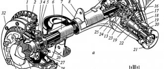
| Rice. 4.1. Front suspension assembly: 1 – upper support of the telescopic strut; 2 – upper support cup; 3 – compression stroke buffer with protective casing; 4 – compression buffer support; 5 – suspension spring; 6 – lower spring support cup; 7 – steering rod ball joint; 8 – steering knuckle; 9 – telescopic stand; 10 – eccentric washer; 11 – adjusting bolt; 12 – rack bracket; 13 – steering knuckle; 14 – front brake protective cover; 15 – brake disc; 16 – retaining ring; 17 – wheel hub nut; 18 – splined shank of the wheel drive hinge housing; 19 – guide pin; 20 – wheel hub bearing; 21 – ball joint; 22 – suspension arm; 23 – adjusting washers; 24 – stabilizer strut; 25 – stabilizer bar; 26 – stabilizer bar cushion; 27 – stabilizer bar mounting bracket; 28 – body bracket for mounting the suspension arm; 29 – suspension arm extension; 30 – bracket for fastening the extension; 31 – protective cover of the ball pin; 32 – ball pin bearing; 33 – ball pin; 34 – ball pin body; 35 – suspension strut rod; 36 – outer body of the upper support; 37 – inner body of the upper support; 38 – upper support bearing; 39 – rubber element of the upper support; 40 – travel limiter of the upper support; 41 – protective cap of the upper support; B - zone for monitoring the suspension joint |
Apply relative position marks on the head of the adjusting bolt 11 (see) and on the strut bracket so that during assembly the marks can be aligned to approximately maintain the camber of the front wheels. Then unscrew the bolts securing the steering knuckle 13 to the strut bracket and remove the steering knuckle as an assembly with the hub. Do not press the wheel hub out of the bearings unless necessary, as pressing it out may damage the bearing. If the wheel hub or the bearing itself is damaged, press out the hub and bearing using a press and mandrels 67.7853.9583 and 67.7853.9587.
| Rice. 4.5. Steering knuckle and parts of the front wheel hub: 1 – steering knuckle; 2 – outer mud ring; 3 – hub bearing; 4 – wheel hub; 5 – thrust washer; 6 – nut; 7 – retaining ring; 8 – internal dirt ring |
When pressing out the hub, the bearing may be disassembled and the outer half of the inner ring may remain on the hub. In this case, it must be removed with a universal puller. For this purpose, there are two special recesses in the hub. Then remove the retaining rings 7 () and use the mandrel 67.7853.9587 to press the bearing out of the steering knuckle. If the hub bore diameter is damaged, replace it.
The procedure for installing a new bearing is as follows:
| Rice. 4.6. Pressing the bearing into the steering knuckle: 1 – steering knuckle; 2 – bearing; 3 – mandrel |
– install the outer retaining ring 7 (see ) into the steering knuckle 1 and press in the bearing 3. At the same time, make sure that the mandrel 3 () presses only on the outer ring of the bearing, otherwise it may be damaged;
| Rice. 4.7. Pressing in the wheel hub: 1 – mandrel; 2 – steering knuckle; 3 – hub |
– install the internal retaining ring and begin pressing the hub using mandrel 67.7853.9530. When pressing it in, mandrel 1 () must rest on the inner ring of the bearing. After installing the steering knuckle assembly with the hub on the car, install a new or used, but on another car, nut and tighten it to a torque of 225.6–247 N·m (23–25 kgf·m) and lock it.
Unscrew the bolts securing the protective casing 14 (see) of the brake disc and remove it.
| Rice. 4.8. Dismantling the front suspension strut: 1 – device 67.7823.9545; 2 – telescopic stand; 3 – spring |
| Rice. 4.9. Front suspension elements: 1 – protective cap; 2 – limiter of the compression stroke of the support; 3-upper rack support; 4 – upper support bearing; 5 – upper spring cup; 6 – front suspension spring; 7 – adjusting bolt; 8 – eccentric washer; 9 – protective casing; 10 – compression progress buffer |
Install the suspension strut into fixture 67.7823.9545 (), compress the suspension strut spring. Holding the rod with wrench 67.7812.9535, unscrew the nut on the rod using wrench 67.7812.9533. Remove limiter 2 (), upper support 3 assembled with bearing. Having unloaded the spring 6, remove it and the upper support cup 5, and then the compression stroke buffer 10 with casing 9.
Before further disassembling the rack, check its condition. With the rack in a vertical position (rod up), perform several full stretch-compression strokes, after which the rod should move without dips or jams and there should be no knocks or extraneous noise. Liquid leakage, deformation and destruction of the rack body, support cup, brackets and rack swing arm are also not allowed. Slight sweating at the top of the strut housing is not a sign of malfunction and does not warrant replacement or repair of the strut strut.
Carry out a more accurate assessment of the performance of the rack on a dyno using the diagram taken, as indicated above.
| Rice. 4.10. Removing the compression stroke limiter support: 1 – mandrel; 2 – compression stroke limiter support; 3 – rack bracket |
If it is necessary to repair the rack, clamp its bracket in a vice so that its jaws are perpendicular to the jaws of the vice (). With this fastening, the possibility of deformation of the rack is eliminated.
Disassemble the rack using tool kit 67.7824.9518 in the following order:
– remove support 2 (see) of the compression stroke buffer, to do this, tap the support with light blows of a hammer on a flat drift from bottom to top and in a circle;
| Rice. 4.11. Unscrewing the nut of the strut housing: 1 – wrench 67.7811.9510; 2 – nut |
– unscrew the housing nut with a wrench 67.7811.9510 (), remove the working cylinder assembled with the rod and its parts from the rack housing;
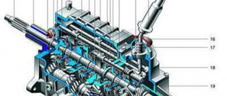
| Rice. 4.2. Telescopic stand: 1 – compression valve body; 2 – compression valve discs; 3 – throttle disk of the compression valve; 4 – compression valve plate; 5 – compression valve spring; 6 – compression valve cage; 7 – recoil valve nut; 8 – recoil valve spring; 9 – recoil valve plate; 10 – recoil valve disc; 11 – throttle disk of the recoil valve; 12 – piston; 13 – bypass valve plate; 14 – bypass valve spring; 15 – plunger; 16 – plunger spring; 17 – rod guide bushing with a fluoroplastic layer; 18 – guide bushing cage; 19 – sealing ring of the rack housing; 20 – rod seal; 21 – oil seal cage; 22 – gasket of the rod protective ring; 23 – rod protective ring; 24 – nut of the strut body; 25 – compression buffer support; 26 – rod; 27 – spring cup; 28 – rotary lever; 29 – rod limit sleeve; 30 – rack body; 31 – cylinder; 32 – drain tube |
– remove the protective ring 23 from the rod (see ), gasket 22, race 21 assembled with oil seal 20;
– by pressing on the compression valve plate, drain the liquid from the cylinder, to do this, repeatedly move the rod by the amount of its full stroke, without hitting the compression valve, so as not to deform its holder;
– having installed the compression valve in the mandrel from kit 67.7824.9518, clamp it in a vice and lightly rock the cylinder by hand until the compression valve is disconnected from the cylinder;
– pushing the rod down, remove the piston assembly with the rod through the lower hole of the cylinder; At the same time, make sure that the fluoroplastic coating of the guide bushing is not damaged;
– hold the rod in a vice by the flats on its shank and unscrew the nut 7 (see) of the recoil valve, then remove the parts of the recoil valve, piston 12 and parts of the bypass valve from the rod;
– having freed the rack body from the vice, drain the liquid from it;
| Rice. 4.12. Removing the rod guide bushing: 1 – guide bushing; 2 – cylinder |
– carefully use a copper hammer or a special drift to knock out the guide sleeve () from the working cylinder; At the same time, make sure that no nicks appear on the cylinder;
| Rice. 4.2. Telescopic stand: 1 – compression valve body; 2 – compression valve discs; 3 – throttle disk of the compression valve; 4 – compression valve plate; 5 – compression valve spring; 6 – compression valve cage; 7 – recoil valve nut; 8 – recoil valve spring; 9 – recoil valve plate; 10 – recoil valve disc; 11 – throttle disk of the recoil valve; 12 – piston; 13 – bypass valve plate; 14 – bypass valve spring; 15 – plunger; 16 – plunger spring; 17 – rod guide bushing with a fluoroplastic layer; 18 – guide bushing cage; 19 – sealing ring of the rack housing; 20 – rod seal; 21 – oil seal cage; 22 – gasket of the rod protective ring; 23 – rod protective ring; 24 – nut of the strut body; 25 – compression buffer support; 26 – rod; 27 – spring cup; 28 – rotary lever; 29 – rod limit sleeve; 30 – rack body; 31 – cylinder; 32 – drain tube |
– remove spring 16 (see) and plunger 15 of the hydraulic buffer from the cylinder;
– disassemble the compression valve, for which remove the holder 6, and then successively remove spring 5, plate 4 and valve discs 2 and 3 from the body.
Assembly
Assemble the front suspension strut in the reverse order of disassembly, taking into account the following:
– ensure the cleanliness of the workplace and all parts of the rack;
– make sure that there are no foreign impurities in the liquid, filter it if necessary;
– make sure that the threads of the recoil valve nut are not damaged when unscrewing it with an open rod;
– inspect the rod at the core location; if the deformation of the thread is large and does not allow screwing on the recoil valve nut without damaging its thread, upset the rod thread at the core location;
– the throttle disc of the front strut recoil valve has three grooves along the outer diameter, and the throttle disc of the rear shock absorber has four;
– the throttle disk of the front suspension strut compression valve has three grooves along the inner diameter, and the throttle disk of the rear shock absorber has two;
– tighten the recoil valve nut to a torque of 12.7–17.5 N m (1.3–1.8 kgf m), then lock it by opening the threaded end of the rod in previously undeformed areas; the moment of unscrewing the nut after opening must be at least 19.6 N m (2 kgf m);
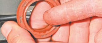
– it is recommended to replace the oil seal and O-ring of the strut housing with new ones during repairs;
– fill the working surface of the oil seal (between the sealing edges) with CV joint grease-4 in an amount of 0.3–0.4 g;
– fill the strut body and cylinder with (320±5) cm3 of liquid for shock absorbers, and fill the rear shock absorber with (250±5) cm3;
– tighten the strut housing nut with the rod fully extended using the wrench 67.7811.9510/11, the tightening torque is 117–147 N m (12–15 kgf m) (for the rear shock absorber the tightening torque is 69–88 N m (7–9 kgf m) m);
– after tightening the nut, caulk the strut body. The torque for unscrewing the nut after caulking must be at least 294 N m (30 kgf m);
– after assembling the compression valve, make sure there is free movement of the valve discs and discs;
– press the compression valve into the cylinder using a special mandrel from the kit 67.7824.9518, then once again make sure there is free movement of the plate and discs;
– to install and press the rod guide bushing into the cylinder, use a special mandrel from the kit 67.7824.9518;
– install springs of the same class on the suspension.
| NOTE Springs are divided into two classes according to their length under the control load: A and B. Class A springs are marked with yellow (white)* paint on the outside of the middle turns, and class B springs are marked with green (blue)* paint |
In exceptional cases, if class A springs are installed on the front suspension, but there are no springs of this class for the rear suspension, it is allowed to install class B springs on the rear suspension. But if class B springs are installed on the front suspension, then install only class B springs on the rear suspension .
Disassembly and assembly of the suspension arm, brace and bracket
Disassembly
Having noted the number of adjusting washers 23 installed at the ends of the extension (see), unscrew the nuts and disconnect the extensions from the suspension arms 22 and from the brackets 30.
| Rice. 4.13. Pressing out rubber-metal hinges from the suspension arm and the brace mounting bracket: 1 – bushing; 2 – suspension arm; 3 – rubber-metal hinge; 4 – mandrel; 5 – device 67.7823.9540; 6 – bracket for fastening the brace; 7 – rubber-metal hinge; 8 – mandrel |
If the rubber-metal joints of the lever and extension are worn, damaged or destroyed, press them out. To press out and press in the extension joint, use a special tool. Press out and press the lever joint and the front extension joint with tools 67.7823.9535 and 67.7823.9540 ( and ).
| Rice. 4.14. Pressing in rubber-metal hinges: suspension arm and brace mounting bracket: 1 – mandrel; 2 – rubber-metal hinge; 3 – guide sleeve; 4 – suspension arm; 5 – support sleeve; 6 – mandrel; 7 – rubber-metal hinge; 8 – bracket for fastening the brace; 9 – support sleeve; A - surface with hinge markings |
Before pressing in rubber-metal hinges and rubber bushings, generously lubricate the hinge sockets and their outer surface with a 30–35% soap solution or IGP-30 oil. Observe precautions to prevent damage to the hinges during pressing (the appearance of scoring, cracks or tears of rubber).
After pressing, the hinges should be symmetrically located in their sockets and should not have any places drawn into the sockets or bulging out of them.
After pressing the hinges and before starting to operate the vehicle, it is necessary to wait at least 24 hours.
When pressing the front brace joint into the bracket, install it with the marked part facing out. The marking is applied on surface “A” (see) of the thrust collar of the smaller diameter hinge.
Assembly
| Rice. 4.15. Assembling a suspension arm with a stretcher: 1 – stretcher; 2 – suspension arm; A - distance between the axis of the lever and the center of the extension |
When assembling a lever with a stretcher, reinstall the removed adjusting washers so that the chamfers on them face toward the thrust end of the stretcher. Before tightening the extension nut, install the lever and the extension on a special device that provides a distance A () between the axis of the lever and the center of the extension equal to 10 mm, and fix the extension. In this position, tighten the extension fastening nut to a torque of 160–176.4 N·m (16.3–18 kgf·m). Then remove the lever assembly from the device and install adjusting washers at the other end of the extension, following the rules for their installation. Then secure the bracket with a nut, tightening it only until the gap in the joint is selected. Carry out the final tightening of the nut on the vehicle as indicated in the chapter “Installation of components and parts of the front suspension”.
When installing protective covers for ball joints, put 6 g of ShRB-4 lubricant into each cover.
Dismantling and assembling the upper support of the suspension strut
If wear, damage, or corrosion appears on the bearing of the upper support of the telescopic strut, it should be replaced. To do this, use a special mandrel to flare the support body, and then, using mandrel 67.7853.9588, press the bearing out of the support body under a press, using stand 67.7822.9530.
| Rice. 4.16. Crimping the support body: 1 – mandrel; 2 – upper support; 3 – stop |
Before pressing in a new bearing, make sure that there are no burrs or burrs in the bearing seat. Eliminate any irregularities found using fine-grained sandpaper. Using a mandrel 67.7853.9588, press the bearing into the support body, then crimp the support body on a press in four equally spaced places that were not previously deformed, using a special mandrel () for this purpose. After compressing the support housing, the bearing should not move in the axial direction. The pullout force of the outer ring must be at least 5880 N (600 kgf).
If it becomes necessary to replace the bolt securing the upper support to the body, press it out. After pressing in the new bolt, to ensure reliable fixation, weld its head at one point using electric arc welding. At the same time, avoid overheating of the support, as well as contact with splashes of metal and slag.
Press out worn, damaged or destroyed rubber-metal hinges of the stabilizer struts using a press using special mandrels, as indicated in half section. “Disassembly and assembly of the suspension arm, brace and bracket.”
When assembling the anti-roll bar, install the mounting brackets at a distance of 350 mm from the center line of the bar.
Checking technical condition
Telescopic stand
Wash all parts with kerosene and dry. Carefully check that the parts meet the following requirements:
– the disks of the compression and rebound valves, as well as the bypass valve plate, must not be deformed; non-flatness of the bypass valve plate is allowed no more than 0.05;
– the working surfaces of the piston, piston ring, guide bushing, rod, cylinder, recoil buffer plunger and valve parts must be free of scuffs, dents and signs of wear that could affect the normal operation of the strut;
– the working edges of the oil seal must be free of damage or wear;
– risks, scuffing and peeling of the fluoroplastic layer at the rod guide bushing are not allowed;
– the springs of the recoil and compression valves, as well as the plunger of the recoil buffer, must be intact and sufficiently elastic;
– the inner surface of the rack body must be clean, without marks or damage, the threads must be in good condition; check the tightness of the rack housing with air at a pressure of 0.3 MPa (3 kgf/cm2); air leakage is unacceptable;
– the rack body, bracket, spring cup and swing arm must not be deformed or damaged;
– the compression stroke buffer and the protective casing must not be damaged or destroyed.
Welding work on the rack is not allowed, as this may affect changes in wheel alignment angles and the performance of the rack.
Suspension arms
The deformation of the suspension arms is determined by tool 67.7851.9508. The suspension arm assembly with the ball joint is installed so that the centering mandrel articulates with the cone of the arm's ball joint pin, and the mounting pins of the device fit into the middle and outer holes of the arm.
A sign of deformation is the impossibility of inserting the lever mounting pins without force or poor articulation of the mandrel along the cone of the hinge pin.
Ball joints
Make sure the protective covers of the hinges are intact. Tears, peeling of rubber from metal fittings, traces of lubricant leakage through the cover are unacceptable. A slight squeeze of lubricant through the sprue hole in the ball joint housing, located in the upper part of the housing, is allowed.
Check for wear on the ball joint working surfaces by manually turning the ball joint. Significant (over 0.7 mm) free movement of the finger or its jamming is unacceptable.
| Rice. 4.17. Checking the ball joint on device 02.8701.9502: 1 – ball joint; 2 – indicator; 3 – torque wrench; 4 – device 02.8701.9502; A - diagram for checking radial clearance; B - scheme for checking axial clearance |
An accurate check of the condition of the ball joint based on the radial and axial clearance is carried out using fixture 02.8701.9502. To do this, install the ball joint 1 () into the socket of the device and tighten it with a screw. Install indicator 2 into the fixture bracket so that its leg rests against the side surface of the hinge body and the indicator arrow is at zero.
Install torque wrench 3 in the upper socket of the device and, applying a torque of 196 N m (20 kgf m) to it alternately in both directions, determine the total radial clearance in the ball joint using the indicator. If it exceeds 0.7 mm, replace the hinge with a new one.
Similarly, check the axial play in the ball joint, having first changed its fastening in the device, as indicated in. The axial clearance in the hinge is allowed no more than 0.7 mm.
Anti-roll bar
Check whether the rod is deformed and whether its ends are in the same plane; if the deformation is insignificant, then straighten the rod; if the deformation is significant, replace the rod.
Check the condition and safety of the cushions in the boom brackets. If the cushions are worn or damaged, replace them.
Check the deformation of the stabilizer struts with a gauge; If the gauge pins do not fit into the post holes, replace it.
Suspension springs
Inspect the springs carefully. If cracks or deformation of the coils are found, replace the spring with a new one.
| Rice. 4.18. Parameters for checking the front suspension spring: H - spring length under load |
To check the spring, press it three times until the coils touch. Then apply a load of 3188 N (325 kgf) to the spring. The length of the spring “H” () under the specified load must be at least 201 (182)* mm. Compress the spring along the axis of the spring; The supporting surfaces must match the surfaces of the support cups on the telescopic stand.
If a spring with a yellow marking (class A) has a length of less than 207 (188)* mm, change its marking to green (class B).
Stretch marks
The deformation of the stretch marks is determined by device 67.7851.9509. If there is slight deformation, straighten the stretcher using a press; if straightening is impossible, replace the stretcher with a new one.
Rubber-metal joints
The signs that determine the need to replace the hinges are described above (see “ Determining the condition of suspension parts on a car ”).
Upper support of telescopic stand
| Rice. 4.19. Checking the elastic deformation (settlement) of the upper support: A - control size |
Check the elastic characteristics (settlement) of the upper support by applying a load of 6860 N (700 kgf) to the support bearing () and measuring the distance “A” from the end of the bearing to the end of the outer housing of the support. This distance should not exceed 29 mm. Otherwise, replace the support with a new one.
Make sure that the bearing has no axial movement in the support housing. The bearing must not become corroded, damaged or seized due to wear. In these cases, replace the bearing with a new one.
Check the condition of the support housing. Peeling of rubber, rips, and cracks of the support are not allowed.
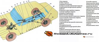
Repair manual for the suspension of a Lada 2113 car, eliminating noise and knocking in the suspension of a Lada 2114, replacing the strut of a VAZ 2113, VAZ 2115, VAZ 2114. Checking and repairing the chassis of a VAZ 2115 with your own hands. Description of the running gear of fret 2113. Operation of the front and rear suspension of fret 2114.
The front suspension of the Lada Samara 2 is independent, telescopic, with hydraulic shock absorber struts, coil springs, lower wishbones with braces and a stabilizer bar.
VAZ 2115 front suspension assembly: 1 – upper support of the telescopic strut; 2 – upper support cup; 3 – compression stroke buffer with protective casing; 4 – compression buffer support; 5 – suspension spring; 6 – lower spring support cup; 7 – steering rod ball joint; 8 – steering knuckle; 9 – telescopic stand; 10 – eccentric washer; 11 – adjusting bolt; 12 – rack bracket; 13 – steering knuckle; 14 – front brake protective cover; 15 – brake disc; 16 – retaining ring; 17 – wheel hub nut; 18 – splined shank of the wheel drive hinge housing; 19 – guide pin; 20 – wheel hub bearing; 21 – ball joint; 22 – suspension arm; 23 – adjusting washers; 24 – stabilizer strut; 25 – stabilizer bar; 26 – stabilizer bar cushion; 27 – stabilizer bar mounting bracket; 28 – body bracket for mounting the suspension arm; 29 – suspension arm extension; 30 – bracket for fastening the extension; 31 – protective cover of the ball pin; 32 – ball pin bearing; 33 – ball pin; 34 – ball pin body; 35 – suspension strut rod; 36 – outer body of the upper support; 37 – inner body of the upper support; 38 – upper support bearing; 39 – rubber element of the upper support; 40 – travel limiter of the upper support; 41 – protective cap of the upper support; B - zone for monitoring the suspension joint
The main element of the suspension of the VAZ 2114, VAZ 2115, VAZ 2113 is a telescopic, hydraulic shock absorber strut 9, the lower part of which is connected to the steering knuckle 13 with two bolts. The upper bolt 11, passing through the oval hole of the strut bracket, has an eccentric collar and an eccentric washer 10. When the upper bolt is turned, the camber of the front wheels changes. The following are installed on the telescopic rack: a coil spring 5, a polyurethane foam buffer 3 compression strokes, as well as the upper support 1 of the rack assembled with a bearing 38.
Telescopic strut VAZ 2114: 1 – compression valve body; 2 – compression valve discs; 3 – throttle disk of the compression valve; 4 – compression valve plate; 5 – compression valve spring; 6 – compression valve cage; 7 – recoil valve nut; 8 – recoil valve spring; 9 – recoil valve plate; 10 – recoil valve disc; 11 – throttle disk of the recoil valve; 12 – piston; 13 – bypass valve plate; 14 – bypass valve spring; 15 – plunger; 16 – plunger spring; 17 – rod guide bushing with a fluoroplastic layer; 18 – guide bushing cage; 19 – sealing ring of the rack housing; 20 – rod seal; 21 – oil seal cage; 22 – gasket of the rod protective ring; 23 – rod protective ring; 24 – nut of the strut body; 25 – compression buffer support; 26 – rod; 27 – spring cup; 28 – rotary lever; 29 – rod limit sleeve; 30 – rack body; 31 – cylinder; 32 – drain tube
The upper support of the VAZ 2113 is attached with three self-locking nuts to the body mudguard strut. Due to its elasticity, the support ensures that the strut “swings” during suspension movements and dampens high-frequency vibrations. A bearing built into it allows the rack to turn along with the steered wheels. Parts of a telescopic hydraulic shock absorber are mounted in the strut housing. A hydraulic recoil stroke buffer is installed in the upper part of the cylinder, consisting of a plunger 15 and a spring 16. It limits the movement of the rod during the recoil stroke. The lower part of the steering knuckle 13 is connected by a ball joint 21 to the wishbone 22 of the suspension. Braking and traction forces are perceived by longitudinal braces 29, which are connected through rubber-metal hinges to transverse arms 22 and brackets 30. At the junction of the brace with the lever of the VAZ 2113, VAZ 2114, VAZ 2115 and the bracket, adjusting washers 23 are installed, which adjust the angle of the longitudinal inclination of the axis turn. A double-row angular contact bearing 20 of a closed type is mounted in the steering knuckle, on the inner rings of which the wheel hub is mounted with interference. The bearing is tightened with a nut 17 on the shank 18 of the outer wheel drive joint housing and is not adjustable. All front and rear wheel hub nuts are the same and have right-hand threads. The anti-roll bar is a bar 25, the knees of which are connected to the transverse arms 22 of the suspension through drains 24 with rubber and rubber-metal hinges. The middle (torsion) part of the rod is attached to the body with brackets 27 through rubber pads.