What do you need to know about the Niva 21213 gearbox?
The Niva car is positioned as an SUV that has increased cross-country ability. Due to this, there is a demand for the car. A durable load-bearing body has been installed. The Niva 2131 model is built on the basis of the LADA 4×4. Its tuning allows you to change the exterior and performance characteristics for the better. Since the mid-1990s. Injection engines have become available for Niva cars.
In addition to passenger cars, self-propelled vehicles are also produced under the Niva brand. In particular, this is Niva SK 5. This vehicle is a combine harvester designed for harvesting crops. The machine runs on diesel fuel.
Other parts and mechanisms
Among other elements of the unit in question, the following devices can be noted:
- Transfer of movement back. It does not have a synchronizer; activation is carried out by introducing an intermediate gear with a driving analogue of the secondary shaft and the same part on the intermediate roller.
- The Niva-2121 gearbox has a control drive consisting of three rods that are aggregated with forks. The last elements are placed in the sockets of the sliding clutches, and the reverse gear analogue is placed in the groove of the intermediate gear.
- The lubrication mechanism involves processing the parts of the assembly by splashing. The shafts are sealed with oil seals; the secondary shaft of the fifth gear has an oil deflector in the form of a washer. The filled oil level should reach the bottom edge of the fill socket.
Features of the gearbox on Niva
VAZ 21213 car with an engine capacity of 1.7 liters. can develop power up to 79 horsepower. Fuel consumption averages 10 liters per 100 km. As is typical for gasoline engines, there is a central injection system. Such vehicles should be fueled with AI-95 gasoline.
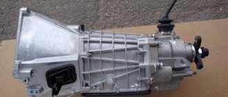
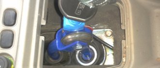
The Niva gearbox (VAZ 21213) is a five-speed manual transmission. The Niva's transmission has permanent all-wheel drive. It should be noted that there is a reliable gearshift lever extension on the Niva. Thanks to it, speed modes can be changed quickly. The existing camshaft drive is chain driven. The crankshaft includes several connecting rods and main journals. The crankshaft is distinguished by its durability and is made of cast iron. The timing mechanism is covered with a cover. There is an oil filler neck here.
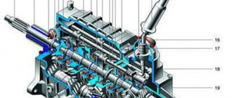
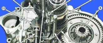
Niva checkpoint diagram
A transfer case is installed on the Niva 2121. Its peculiarity is that it has both high and low gears. It is important to use an increased one if you need to save on fuel consumption. In the event that movement occurs over rough terrain, a lower gear helps out. However, in this case, fuel consumption will increase.
Transfer case diagram
The transfer case allows you to disable one of the drive axles if necessary. The transfer case includes shafts, a differential, and a gearshift clutch. The main failures are expressed in the fact that over time its main components wear out, as a result of which the box may overheat and problems with switching on the bridge may appear. Repair of the VAZ 21213 gearbox is required if characteristic vibration from this unit begins to be observed.
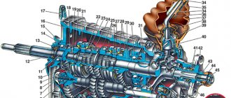
Thus, the popularity of the car is explained by the fact that it has an all-wheel drive system. The speed box diagram shows that it includes a large number of components that interact with each other, ensuring excellent performance of the car.
Assembly
Assemble the gearbox in the reverse order of disassembly. Please note that:
- the axis of the reverse intermediate gear is secured before the shafts are installed in the gearbox housing with a torque of 78 N·m (7.8 kgf·m);
- Before installing the 5th gear and reverse fork rod into the crankcase, install a spacer bushing on it;
- the inner ring of the bearing is pressed onto the gear block of the 5th gear and reverse gear, and the outer ring is pressed into the socket of the rear cover;
- The secondary shaft rear bearing is pressed onto the shaft to facilitate installation of the rear cover;
- Install intermediate gear 1 (Fig. 3-23) for reverse gear, gear 3 and fork 4 at the same time;
- when assembling the gear shift lever, coat the ball head or ball joint with lubricant LSTs-15 or Litol-24;
- Tighten the gear block mounting bolt to a torque of 78 N·m (7.8 kgf·m);
- When installing the clutch housing with the front cover of the gearbox, the hole in the front cover should be located as shown in Fig. 3-15;
- Before installation, coat the working surface of the oil seals with Litol-24 lubricant;
- When installing oil seals and bearings, use mandrels 41.7853.4028, 41.7853.4032, 41.7853.4039.
◀Removal and installation of the VAZ-21213 Niva gearbox, Gearbox
Diagnostics and repair of the speed box
To carry out a full diagnosis, the speed box must be removed. As a rule, there is a need for this if vibrations, extraneous noise, or oil leakage increase during movement.
How to remove the box? Before you begin removing the gearbox, you must remove the transfer case. Without an inspection hole, it will be difficult to carry out repair work, for example, unscrewing the cardan shafts from the transfer case. The stabilizer can also be removed. The housing of the air filter element must be removed.
In order to remove the gearbox, you should disconnect the lever rod, the clutch housing cover fastenings, the driveshaft, bolts, nuts, and remove the bracket. The suspension of the power unit is adjacent to the body. To remove it you need to unscrew the fastening nuts.
To extend the service life of the VAZ 21213 gearbox, it is advisable to periodically check the level of transmission fluid and change it in a timely manner.
It should be noted that often the appearance of extraneous noise from the gearbox is a consequence of the fact that there is a low level of transmission oil in the system.
Mineral oil can be added to the machine. However, semi-synthetic and synthetic options have better performance. The advantage of the latest types of oils is that even in winter the gears will be easily engaged.
Timely maintenance of the Niva gearbox allows you to avoid a complete overhaul of the gearbox. Assembling all the dismantled parts is a painstaking task, so it should be trusted to professionals. Replacing the gearbox input shaft bearing is a common procedure that is ordered at a service center.
Didn't find the information you are looking for? on our forum.
Disassembly
Wash the gearbox and install it on a stand. Drain the oil and remove the bottom cover with gasket.
Remove the clutch release fork, and from the guide sleeve of the front cover of the gearbox, remove the clutch assembly with bearing and connecting spring.
Remove the clutch housing with the gasket and the front cover of the gearbox along with the oil seal and spring washer (Fig. 3-15).
Rice.
3-15. Internal view of the clutch housing. The black arrows indicate the nuts securing the clutch housing to the gearbox; The white arrow indicates the hole in the front cover for releasing oil from the gearbox housing to prevent oiling of the clutch discs.
Unscrew the reverse light switch, being careful not to deform its housing.
Remove the bolt securing the 3rd and 4th gear shift fork. Install clamp 41.7816.4068 on the input shaft or engage two gears at the same time. This will prevent the primary, secondary and intermediate shafts from turning and will allow subsequent disassembly operations to be performed.
Note. Since 1997, the design of the following parts has changed at the rear end of the transmission output shaft:
- instead of the metal centering ring 26 (Fig. 3-31) and the locking ring, a rubber centering sleeve is installed;
- instead of seal 25 with spring 24, a seal without a spring is installed;
- lock washer 22 is replaced with a spring washer;
- nut 23 is installed on sealant UG-9 or UG-10.
Remove the retaining ring from the end of the transmission output shaft (Figure 3-16).
Having straightened the lock washer, unscrew the nut a few turns to move the centering ring of the elastic coupling, and tighten the nut again. Using a pusher A.40006/1 with a puller A.40005/4, remove the centering ring of the elastic coupling of the propeller shaft from the end of the secondary shaft (Fig. 3-17).
Remove the elastic coupling centering ring seal with the spring from the end of the secondary shaft, unscrew the nut and remove the elastic coupling flange using a puller A.40005/3/9B/9C (Fig. 3-18).
Rice. 3-18. Removing the elastic coupling flange using a puller A.40005/3/9B/9C:
1 – elastic coupling flange;
2 – puller A.40005/3; 3 – stripper strip A.40005/3; 4 – bolts securing the device to the flange. Before removing the rear cover, set the gear shift lever to the neutral position, unscrew the gear selector mounting nuts and remove the gear shift lever (Fig. 3-19) as an assembly with the selector mechanism. One of the cover fastening nuts is unscrewed from inside the gearbox housing with the bottom cover removed. When removing the rear cover, it must be moved not only backwards, but also turned to prevent it from touching the reverse and 5th gear gear block.
After removing the inner ring of the rear bearing 43 (Fig. 3-12) and the bearing spacer 44 from the secondary shaft, loosen the bolts securing the cover 5 (Fig. 3-20) and unscrew the bolts 2 and 4 securing the gear block and the 5th gear shift fork and the rear progress. Remove the oil deflector washer 45 fig. 3-12), and then bushing 1 (Fig. 3-21) of the fifth gear gear and remove rod 1 (Fig. 3-22) from fork 2. In this case, spacer bushing 3 is removed from the rod. Then remove the block from the slot of the intermediate shaft gears 4.
Rice. 3-20. Unscrewing the bolts securing the gear block and the 5th gear and reverse fork:
1 – reverse intermediate gear; 2 – bolt for fastening the gear block; 3 – fork rod; 4 – fork mounting bolt; 5 – clamp cover.
Rice. 3-22. Removing the 5th gear and reverse fork rod:
1 – fork rod for 5th gear and reverse gear;
2 – fork for selecting 5th gear and reverse gear; 3 – spacer sleeve; 4 – gear block. At the same time, remove the reverse intermediate gear 1 (Fig. 3-23) from the axle, gear 3 assembled with the clutch and fork 4 from the secondary shaft.
Rice. 3-23. Removing the reverse intermediate gear, fifth gear gear assembly with synchronizer and fork:
1 – reverse intermediate gear; 2 – fifth gear engagement clutch; 3 – gear V gear and reverse gear; 4 – fork.
Using shaped mandrels (like screwdrivers), remove hub 4 (Fig. 3-24) of the 5th gear synchronizer and reverse driven gear 2 from the key.
Rice. 3-24. Removing the reverse driven gear and 5th gear synchronizer clutch hub:
1 – intermediate shaft;
2 – reverse driven gear; 3 – axis of the reverse intermediate gear; 4 – fifth gear synchronizer clutch hub; 5 – secondary shaft; 6 – fork rod for 1st and 2nd gears; 7 – fork rod for 3rd and 4th gears. Using shaped mandrels (such as screwdrivers) and rod drifts, remove the front and rear intermediate shaft bearings from the gearbox housing. On the inner rings of a double-row bearing, place marks according to which these rings should be installed in their original places in the outer ring of the bearing.
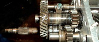
Remove the intermediate shaft from the gearbox housing by tilting it as shown in Fig. 3-25.
Remove the shift fork rods of 1st, 2nd, 3rd and 4th gears from the gearbox housing one by one, having previously unscrewed the fork mounting bolts. When removing the rods, simultaneously remove three locking blocks 6 (Fig. 3-26). Remove the locking plate (Figure 3-27) of the secondary shaft intermediate bearing. Unscrew the nut securing the reverse idler gear axle and remove it.
Rice. 3-26. Gear shift drive:
1 – shift fork for III and IV gears; 2 – fork rod for 1st and 2nd gears; 3 – fork rod for 3rd and 4th gears; 4 – shift fork for 1st and 2nd gears; 5 – fork rod for 5th gear and reverse gear; 6 – blocking crackers; 7 – clamp cover; 8 – clamp spring; 9 – ball of clamps; 10 – fork for 5th gear and reverse gear; 11 – head of the fork rod for 5th gear and reverse gear; 12 – gear block of 5th gear and reverse gear; 13 – axis of the reverse intermediate gear; 14 – reverse intermediate gear; 15 – guide plate washer; 16 – guide plate; 17 – gear shift lever housing; 18 – ball joint; 19 – spherical washer; 20 – spring; 21 – thrust washer; 22 – retaining ring.
Using mandrels (like screwdrivers), remove the input shaft along with the bearing and synchronizer ring (Figure 3-28) and remove the needle bearing from the front end of the output shaft.
Knock out the secondary shaft from the intermediate bearing, remove the intermediate bearing and tilt it as shown in Fig. 3-29, remove the secondary shaft assembly with gears, clutches and synchronizer rings from the crankcase. Remove the synchronizer clutch for 3rd and 4th gears from the shaft.
Disassemble the input shaft (Fig. 3-30), for which:
- remove retaining ring 7, blocking ring 6 and synchronizer spring 5;
- Place the shaft on the press and, using a mandrel 41.7816.4069, compress the spring washer 2, remove the locking ring 1, and then the spring washer and bearing 3.
Rice. 3-30. Main shaft details:
1 – retaining ring;
2 – spring washer; 3 – bearing; 4 – input shaft; 5 – synchronizer spring; 6 – synchronizer blocking ring; 7 – retaining ring; 8 – bearing. Disassemble the secondary shaft (Fig. 3-31):
- Remove from the rear side of the shaft gear 11 of the first gear with sleeve 12, hub 3 with sliding clutch 4 for switching 1st and 2nd gears, gear 10 of the second gear together with the synchronizer blocking ring 5;
- install the secondary shaft with mandrel 41.7816.4069 on the press (Fig. 3-32), place support half-rings 3 under the gear III gear and, pressing the mandrel on the spring washer, remove the locking ring 2, then the spring washer 4, the hub of the sliding clutch of shift III and 4th gear and 3rd gear gear.
Rice. 3-31. Secondary shaft details:
1 – retaining ring; 2 – spring washer; 3 – synchronizer hub; 4 – synchronizer clutch; 5 – blocking ring; 6 – synchronizer spring; 7 – washer; 8 – third gear gear; 9 – secondary shaft; 10 – 2nd gear gear; 11 – 1st gear gear; 12 – gear bushing; 13 – bearing; 14 – key; 15 – reverse gear; 16 – fifth gear gear; 17 – oil deflector washer; 18 – spacer sleeve; 19 – rear bearing of the secondary shaft; 20 – oil seal; 21 – elastic coupling flange; 22 – lock washer; 23 – nut; 24 – seal spring; 25 – seal; 26 – centering ring.
Rice. 3-32. Installation of the retaining ring on the secondary shaft:
1 – mandrel 41.7816.4069;
2 – retaining ring; 3 – support half-ring; 4 – spring washer; 5 – press rod. If necessary, disassemble the lever and gear selection mechanism, for which:
- remove the protective cover 10 (Fig. 3-33), locking and thrust rings 6 and 7, spring 5 and spherical washer 4 from the gear shift lever;
- visually mark the location of the parts relative to mark A (Fig. 3-34) marked on the guide plate in order to connect the parts in the same position during assembly;
- Having unscrewed the nuts from the fastening bolts, disconnect the parts of the gear selection mechanism and remove the lever 9, its ball joint 4 and rubber sealing rings 15.
Rice. 3-33. Parts of the lever and gear selection mechanism:
1 – gear shift lever; 2 – gasket; 3 – ball joint; 4 – spherical washer; 5 – spring; 6 – ring; 7 – retaining ring; 8 – flange; 9 – cuff; 10 – protective cover; 11 – handle; 12 – lever rod; 13 – thrust pad; 14 – elastic bushing; 15 – spacer sleeve; 16 – locking sleeve; 17 – gear shift lever housing; 18 – sealing ring; 19- guide plate washer; 20 – guide bar; 21 – spring; 22 – guide plate; 23 – reverse locking plate.
Rice. 3-34. Gear selection mechanism:
1 – guide plate washer; 2 – guide plate; 3 – gear shift lever housing; 4 – ball joint; 5 – spherical washer; 6 – spring; 7, 8 – retaining rings; 9 – gear shift lever; 10 – protective cover; 11 – flange; 12 – reverse locking plate; 13 – spring; 14 – guide bar; 15 – sealing ring; A – risk.