A malfunction of the phase sensor , which is also called a camshaft position sensor, leads to the engine starting to operate in pair-parallel fuel supply mode. That is, each injector fires twice as often. Because of this, fuel consumption increases, exhaust toxicity increases, and problems with self-diagnosis arise. A malfunction of the sensor does not cause more serious problems, but if it fails, replacement is not delayed.
What happens when the camshaft position sensor wears out?
This can happen at any time without any warning. Imagine the following, dear motorists: -You are driving a car along a highway and moving at high speed, and then unexpectedly for you, the engine in your car simply turns off...(?) After in this situation you will experience the unpleasant moments that will be associated with the hydraulic booster or electric power steering turned off and the effectiveness of the braking system deteriorating, then you will immediately park your car on the side of the road, and then you will wonder what happened... A common reason for such unexpected engine shutdown when driving on the road is a malfunction of the camshaft sensor (camshaft position sensor).
Sometimes this camshaft sensor (CMP) can fail without warning, causing the engine to simply stall. In some and certain cases, the driver may not even be aware of the problems that have occurred with the sensor, and this will happen until the car’s engine simply starts.
See also: How a Koenigsegg engine works without a camshaft [Video]
In our article today, dear readers, we will look at the main symptoms of a malfunction of the camshaft position sensor, and at the same time we will tell you what needs to be done in this position to eliminate this malfunction. But first, let's find out together exactly what this sensor does in a car.
Principle of operation
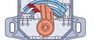
Magnetic induction sensors work completely similar to DPKV. This is a permanent magnet coil placed next to a toothed metal disk made of ferromagnetic material.
When the disk rotates, the magnitude of the magnetic field in the gap between the sensor and the teeth changes, which causes the inductive generation of electrical signals at the coil terminals.
The signals arrive at the ECU input, where they are converted into digital format, and the reference point is formed by skipping one tooth on the disk, which causes a jump in amplitude and phase in the output signal. If there is only one tooth, then the impulse will be single, suitable for synchronizing shafts.
The design of the most common Hall sensor is slightly more complicated. It contains a semiconductor crystal on which an electrical potential difference occurs when it enters a magnetic field. That is, it is enough to attach a magnet to the camshaft sprocket so that the sensor reacts to it during rotation with a single pulse.
The signal is weak, but the sensor contains an amplifier, a comparator and a Schmitt trigger, made in the form of a microcircuit crystal. A fully finished digital logic signal is generated at the output connector.
Optical sensors are very rare; they use interruption or reflection of the light flux between the emitter and the photodetector. With the same subsequent amplification and conversion as in the Hall sensor.
The range is usually chosen infrared, due to the simplicity of emitters, receivers and optimal noise immunity.
What is a Camshaft Position (CMP) Sensor?
The camshaft controls the opening and closing of the intake and exhaust valves.
In the cylinder head of a car engine there are one or two camshafts, which are equipped with special lobes and are designed to operate the intake and exhaust valves. The crankshaft is located in the cylinder block itself, which, when receiving torque from the movement of the pistons in the block, transmits this torque using gears directly to the timing chain (or to the timing belt) to the camshaft.
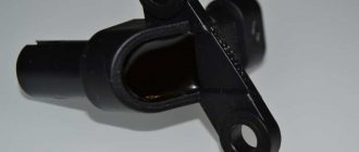
Camshaft
To initially determine which engine cylinder is on stroke, your car's computer monitors the rotation position of the camshaft relative to the position of the crankshaft using the camshaft sensor (CMS). The information received from the CMR sensor is necessary to adjust the timing of the spark supply to the combustion chamber and for the operation of the fuel injectors. Thus, the camshaft sensor directly affects the fuel consumption of the car and the amount of emissions in the exhaust.
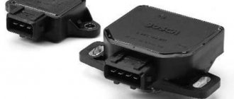
The most common camshaft sensors are: - magnetic and based on the Hall effect. Both types of sensors transmit a voltage signal to the electronic engine control unit or to the vehicle's on-board computer.
The magnetic type of camshaft sensor produces its own alternating current (called a sine wave). Typically this sensor has two wires. Well, a sensor based on the Hall effect uses an external power source to receive a digital signal; as a rule, it already has three wires.
Camshaft position sensor
Depending on the make and type of your vehicle, your engine may have one or more camshaft sensors. There are also two types of CMP sensors that can be used in your car.
FakeHeader
Comments 37
Yes, you can set everything without marks at all, use a screwdriver for the lower part, but it’s more difficult to use the upper part, you have to remove the cover
When replacing the kV rear oil seal, remove the flywheel. And sometimes they put it wrong. Then think about why problems appear
first think about what you wrote
I understand this perfectly well; on the former 11th, the marks on the timing belt did not coincide with the mark on the flywheel. On my Priora I only look at the kv mark by looking at the flywheel
Class. Continue in the same spirit, as long as no one follows you. No offense, but the mark on the flywheel is only for minimal imbalance and does not affect the timing in any way.
Symptoms of a faulty camshaft sensor
Just like any part or component in your vehicle, this CMP sensor will eventually, sooner or later, simply stop working due to wear and tear.
This happens anyway once its maximum service life has expired. This usually occurs due to wear on the internal wire wrap or a component associated with it. Usually, in this case, the engine in the car begins to work intermittently, and the signs of a malfunction can vary in different ways, i.e. depending on the type of sensor wear. For example, the same connector in a sensor may wear out, the same internal sensor circuit may fail, or a component associated with the sensor may fail.
On some types of cars, if the camshaft position sensor is faulty, the transmission may be locked in one of the gears and will be locked until you turn off the engine and start it back. This can be repeated with a certain cyclicity.
- If the camshaft sensor begins to behave incorrectly while the car is moving, i.e. work , then you can immediately feel that your car has begun to move jerkily and at the same time lose speed.
- If the camshaft sensor fails, you may experience a noticeable loss of power from the engine itself. For example, your car simply cannot accelerate over 60 km/h.
- The engine in the car may stall intermittently, and all this is due to a malfunction of the CMR sensor.
- If the sensor fails, you will notice poor engine performance, it will have a loss of dynamism, misfires will begin when the ignition is turned on, jolts during acceleration, popping noises in the exhaust system, etc. irregularities in work.
- On some car models, if the camshaft sensor is faulty, the ignition spark may completely disappear, which will ultimately lead to failure and the engine being unable to start.
After your car's computer detects a malfunction of the camshaft position sensor, which, as you understand, will lead to the appearance (lighting) of the “Check Engine” indicator on the dashboard. After detecting poor operation of the CMR sensor, the computer will automatically record the sensor’s “error code” in its memory. To accurately determine the cause of the malfunction of this camshaft sensor, it is necessary to conduct computer diagnostics of the car, i.e., by thus connecting special equipment to the diagnostic connector of the car. Next, using a special computer program, you can read the “error code”. Below, dear motorists, we present to you a table of diagnostic “error codes” that are directly and directly related to wear on the camshaft sensor.
Signs of the problem in question
Malfunction p0340 in the camshaft position sensor circuit is determined by diagnosing the unit at a service station or using a home scanner. It is almost impossible to identify the breakdown in question visually. However, the following signs may indicate this:
- Sharp excess of fuel consumption;
- Notification by electronic systems about problems;
- Activating the indicator on the instrument panel;
- Increasing the temperature of the engine.
CMP Camshaft Position Sensor Error Codes
| Common CMP Trouble Codes | Cause of camshaft sensor error |
| P0340 CMP | No signal from camshaft sensor |
| P0341 CMP | Incorrect valve timing |
| P0342 CMP | Camshaft sensor circuit low |
| P0343 CMP | Camshaft sensor circuit high |
| p0344 CMP | Unstable signal from the camshaft sensor (intermittent signal) |
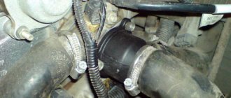
Location of the camshaft sensor in the car
As you probably already guessed, gentlemen, the specific location of this camshaft position sensor varies depending on the make and model of the vehicle.
In most cars, such a sensor can be found approximately around the cylinder head itself. Look for this sensor around the top of the timing belt location or in protected parts of the electrical wiring at the front of the engine. See also: Spark plug faults
The sensor can also be located in the rear of the cylinder head.
Some car models may have a special compartment under the hood for this purpose, in which this camshaft sensor is installed (for example, in certain car models produced by).
Among other things, in some cars (automobiles), the camshaft sensor may be located directly inside the cylinder head.
If necessary, you can look at the owner's manual for your vehicle to find out more precisely where the CMP sensor is located. If you do not have a manual for the repair and maintenance of your car, then you can find it on the Internet or purchase it at a car store, where a large selection of such auto literature is available.
Dear friends, we strongly recommend that all car owners purchase a similar book (repair and maintenance manual) specifically for your modification and model of car. This manual for operating and repairing a car will certainly help each of you in the event of any breakdown or malfunction to cope with the problem that has arisen. It will become your valuable reference for performing routine maintenance on your vehicle and making minor repairs.
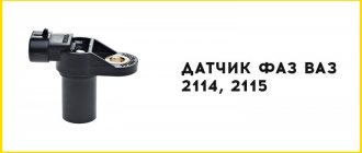
How to check the phase sensor on a VAZ 2114?
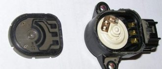
Before checking the VAZ 2114 phase sensor with a multimeter, you must first inspect the part for damage. If there is visible mechanical damage to the product body, it must be replaced with a known working one. If there are no cracks or chips, diagnostics are carried out in the following order:
- Remove the phase sensor from the car. To do this, disconnect the electrical connector and unscrew the fasteners securing the products in the seat. To speed up the process, you can use a ratchet head.
- The multimeter switch is set to DC voltage measurement mode. For testing, select a range of up to 20 volts.
- Measure the voltage at the positive and negative contact pads of the electrical connector. With the ignition on, the multimeter should show the presence of constant voltage.
- Connect the positive and negative contacts to the battery. At the same time, the voltage applied to the part is measured. It should be between 12-14 volts.
- The multimeter is connected to the positive and signal pads, and readings are taken. The voltage between the positive signal contact must be at least 90% of the supply voltage.
- Bring a metal plate to the working surface of the part. As the plate approaches, the voltage should drop to 0.4 volts.
If during diagnostics it turns out that the DPRV has failed, it must be replaced with a new sensor. Otherwise, you should pay attention to the integrity of the electrical wiring. If necessary, clean the connector pads from oxidation.
Troubleshooting Camshaft Sensor (CMP)
If your car’s computer has detected a sensor error and turned on the “Check Engine” icon on the dashboard, then you can easily find out the “error code” yourself, which led to the appearance of the light indication on the dashboard. To do this, we advise each driver to purchase an inexpensive set of diagnostic equipment specifically for computer diagnostics. If you cannot afford to purchase this diagnostic scanner for your car, then contact any inexpensive car service center to diagnose your car, where they will read the “error code” from your car’s computer.
Auto parts from A to Z: Car design for beginners
Once you know from the "error code" that your car has a faulty camshaft sensor or related components, you should do a few simple tests. Please remember, friends, that a fault “code” indicating a potential failure of the camshaft position sensor will not necessarily mean that the CMP sensor itself has failed on the car. After all, it is possible that the cause of the malfunction is not in the sensor itself, but in the sensor connector, or there is damage to the wires connected to it, or perhaps the components directly connected to it have failed.
True, you need to remember the following for yourself, in order to more accurately determine whether the camshaft sensor is functioning normally, you will need to carry out (possibly) quite a lot of diagnostics. It is especially necessary to take into account the following in order to check the effectiveness of the CMR sensor signal itself; in some cases, this may require special equipment, without which it will be difficult to determine the cause of the malfunction.
However, you can do a few simple checks yourself using a digital multimeter (DMM).
First, check the electrical connector at the camshaft sensor and the condition of the wires themselves. Disconnect the connector itself and check for signs of rust or dirt. For example, the same fuel. All this can interfere with good contact for the transmission of electricity.
Next, check for damage to the wires, namely, whether the wires are torn or showing signs of melting from nearby hot surfaces.
In addition, please make sure that the camshaft sensor wires do not touch the spark plugs or ignition coils, which could cause interference and prevent the sensor from transmitting the correct signal.
After the above checks, use a digital multimeter that can test alternating current (AC) voltage or direct current (DC), depending on the specific type of camshaft sensor your vehicle uses .
Also, before testing, you need to set the correct electrical parameters on the multimeter for a specific type of CPM sensor. Typically, such information is indicated in the vehicle repair and maintenance manual.
Some camshaft sensors allow you to create a splitter for the electrical circuit of the CMR sensor; this is done primarily in order to read the signal directly from the sensor itself during its operation in the car.
If the type of your sensor does not allow you to connect the multimeter wires to it, then you can simply disconnect the connector from the sensor and attach a copper wire to it, thus inserting it into each sensor connector.
You can then connect this connector back to the sensor, being careful not to short the wires themselves during testing. If you use (apply) this method, do not forget to first insulate the wires with electrical tape.
Testing a 2-Wire Camshaft Sensor
- If the camshaft sensor in your car has two wires, then this means that the automaker installed a magnetic type of CMP sensor on the car. In this case, you need to set the multimeter to “variable voltage”.
- Have an assistant turn the ignition key without starting the engine.
- Now we need to check the presence of electricity, which should flow through the sensor circuit. Take one terminal of the multimeter and place it against the “ground” (any metal part on the engine). You should place the other contact of the multimeter against each wire that you have already connected to the camshaft sensor connector. If there is no electrical current on any of the wires, then the camshaft sensor is completely faulty.
- Have your assistant start the engine.
- Place one contact of the multimeter against one wire of the camshaft sensor, and connect the other contact of the measuring equipment to the second wire of the sensor. Look at the multimeter display. Check the indicator with the specification specified in the car repair manual. In most cases you will see a fluctuating signal between 0.3 and 1 volt.
- If there is no signal on the display, this means that the camshaft position sensor is faulty.
Three-wire camshaft sensor testing
- After you have checked the camshaft sensor wires and at the same time the condition of its connector, etc., then you have determined for yourself that your car has a three-wire CPM sensor, which means it’s time to check its functionality with a multimeter. To do this, set the multimeter to “constant current” mode.
- Have an assistant turn the key in the ignition, but without starting the engine.
- Place one of the multimeter wires against the “ground” (against a metal bracket, a bolt, or a metal part of the engine). Connect the other wire of the multimeter to the power wire of the sensor. Compare the multimeter readings with the specifications specified in the machine's repair manual.
- Have your assistant start the engine.
- Connect the red lead of the multimeter to the red lead of the sensor, and the black lead of the multimeter to the black lead of the sensor. Compare the multimeter readings with the specifications found in your vehicle's repair manual. If the reading on the multimeter is lower than indicated in the repair manual or the data is completely missing, then most likely the camshaft sensor has failed.
- Remove the camshaft sensor and check it for signs of physical damage or contamination.
If, after self-diagnosis of the camshaft position sensor, you determine that it is fully operational, then there may be a breakdown or malfunction in the vehicle components associated with this sensor.
For example, the timing chain (or timing belt) may have insufficient tension or, on the contrary, may be overtightened. Also, the belt tensioner itself or the timing chain may have worn out. Be very careful friends!!!
With similar problems with the car, the cause of the malfunction may also be a badly worn timing belt. This can cause the camshaft and crankshaft to become out of sync. Ultimately, this camshaft sensor may send the wrong signal to the car's computer. Ultimately, this leads to incorrect ignition and incorrect fuel injection.
Checking three-wire DPRV
Steps to test a three-wire DPRV:
- remove the air filter cover;
- disconnect the 3-pin connector in the DPRV;
- turn on the ignition;
- using a multimeter and cables from the kit, measure the voltage between terminals 1 and 3 of the sensor connector;
- recommended value: 4.5 to 5.5 V;
- turn off the ignition;
- check the wires between the test box and the 3-pin open circuit connector;
- Recommended wire resistance: max. 1.5 Ohm;
- check the wires for short circuit, to battery (+) and ground (GND);
- If the wires and voltage are ok, replace the camshaft position (CMP) sensor.
Engines 1.8L:
IMPORTANT! Before starting any test, the battery voltage must be at least 11.5 volts.
- disconnect the 3-pin camshaft position sensor connector;
- switch DMM to voltage measurement position;
- connect the DMM between the external terminals of the connector;
- Switch the ignition to the “ON” position, but do not start the engine. You should see a minimum of 4.5 volts;
- Now turn the ignition “OFF”;
- connect the VAG 1598/22 test unit to the ECM connector;
- Check the wiring between the test block and the ECM connector using the wiring diagram. Checks must be performed on each of the following points:
- Wire 1 and socket 11.
- Wire 2 and socket 76.
- Wire 3 and socket 67.
- For each of the above tests, the maximum resistance should not exceed 1.5 ohms.
- Check all wires for short circuits.
- when connected and there is voltage between terminals 1 and 3, replace the camshaft position sensor.
- If the wiring is OK but there is no voltage between terminals 1 and 3, replace the ECM.
2.8L engines:
IMPORTANT! Before starting any test, the battery voltage must be at least 11.5 volts.
- disconnect the 3-pin wire connectors from the camshaft position (CMP) sensors;
- connect the DMM to measure voltage on terminals 1 (+) and 3 (ground) of the CMP connector using the adapters from the test kit;
- turn the ignition to the “ON” position, but DO NOT start the engine;
- Measure the voltage between terminals 1 and 3. It should be a minimum of 9.0 volts;
- turn the ignition “OFF”;
- connect the test block to the ECM connector;
- Check the wiring for open circuit between the ECM and the 3-pin connector according to the wiring diagram;
- For the CMP sensor connector on the right cylinder head, measure the following:
- Connector 1 with ECM connector 11.
- Connection terminal 2 to ECM76 connector.
- Connector 3 with ECM 67 socket.
- maximum resistance should not exceed 1.5 Ohms;
- For the CMP sensor on the left cylinder head, measure the following:
- Connector 1 with ECM connector 11.
- Connector 2 with ECM 44.
- Connector 3 with ECM 14.
- for each of these tests the maximum resistance is 1.5 ohms;
- If the wiring and voltage at terminals 1 and 3 are OK, replace the camshaft position sensor;
- If the wiring is OK but there is still no voltage at terminals 1 and 3, replace the ECM.
Functional test of the CMP sensor:
- To perform a functional test of the camshaft position sensor, disconnect the 4-pin connector from the ignition coil and check the DTC memory;
- check the supply voltage of the camshaft position sensor and make sure that it is in order;
- move away the rubber connector of the CMP sensor (the sensor remains connected);
- connect a voltage tester between terminals 1 (+) and 2 (phase);
- start the engine for a few seconds;
- for every second engine revolution, the voltage tester should flash briefly;
- if the voltage indicator does not blink, turn off the ignition and disconnect the 3-pin connector from the camshaft position sensor;
- connect the test block to the ECM connector;
- Check the signal wire for continuity between terminal 2 and socket B2. The maximum resistance should not be more than 1 ohm;
- If the specified value is not obtained, check for a short or open circuit in the wiring between the CMP sensor connector and the ECM;
- if the wiring is ok, connect the DMM between the B2 test block socket and ground;
- turn the ignition key to the “ON” position. Must be at least 4.0 volts;
- if the specified value is not obtained, replace the ECM;
- If a value is obtained, replace the camshaft position (CMP) sensor.