VAZ cars of the 2112 family were produced with two 16-valve valves: 21120 and 21124. The cylinder head of these engines has different intake ports. In theory, there are no other differences. And therefore, the tightening torque of the bolts on the VAZ-2112 cylinder head will be the same if we talk about any 16-valve internal combustion engine. Tightening is performed in three steps, although repair books give another option (it is for 8-valve engines).
The following video shows how the cylinder head is installed in 5 minutes:
What is a cylinder head?
In order to carry out any manipulations with this unit, it is necessary to understand the purpose and operating principle of the device. The cylinder head on the VAZ-2112 model we are considering is made of two options: cast iron, aluminum. Essentially, to put it bluntly, this is the engine cover.
One of the most important components of a vehicle, which is responsible for:
- combustion of gasoline in the engine;
- removal of exhaust gases during the combustion process.
Secondary functions performed by the cylinder head:
- the functional option is carried out thanks to the work of support washers, valve bushings and other parts located in the head;
- thanks to the hole in it, the chain tensioner and the drive of the pulley distributor are installed.
The abbreviation cylinder head is used more often in the terminology of automotive components, since there is not always time to pronounce long and complex names. But it is clear that you need to know all the decryptions. Especially if it is an internal combustion engine (internal combustion engine) and cylinder head (cylinder head).
Therefore, the tension moment must always be adjusted and not carelessly, but correctly, otherwise its functionality will be impaired.
First of all, this is necessary to avoid moisture accumulation at the junction of components in the block and their connections. Thanks to this protection, condensate collects on a special plane to allow liquid to leak out of the engine.
How to carry out repairs
In order to repair the block voice, you will need the following tools:
- Device for compressing valve springs. You can use both “store-bought” and homemade. The main thing is that it is convenient to work.
- Device for pressing out oil seals.
- A tube-shaped mandrel for installing caps.
- "10" keys, hexagons, tweezers and screwdrivers.
Perform the following manipulations:
- Carry out all the steps to remove the head and camshafts.
- Remove all valves using a special device.
- Remove the valve stem seals.
- Replace and grind the valves. Valves need to be replaced if there is damage - burnouts, geometry violations. Be sure to sign which seats you are lapping the valve on - otherwise the tightness will be broken.
- Assemble all the valve drive mechanisms - hydraulic pushers, springs, secure them with bread crumbs.
Process Features
Each engine has its own torque, as does the pin tightening pattern.
The indicator of this moment is influenced not only by the type of engine, but also by other factors that you need to know if you decide to carry out this procedure yourself. The same factors:
- how well the pin holes are lubricated and the very condition of the elements;
- the quality of the bolts plays a big role - bad or old ones may not survive tightening;
- if the thread or the pin itself is deformed, it is better not to tighten it. Because after a short period of time, all elements that do not meet operating standards will fail.
The most urgent need for the tensioning procedure occurs when dismantling the cylinder head, as well as when reinstalling it.
Some car enthusiasts tighten very elongated bolts in 4 stages. In this case, at the second step the torque is 70-85 N*m, which is absolutely unacceptable when working with a Lada Priora engine with 16 valves.
The correct sequence of tightening the keys is very important. Only in this case will the head correctly perform its primary and secondary functions.
Before installation, be sure to clean all threaded bushing holes. Then all the bushings are placed in place, and a gasket is placed on top. All metal elements must be free of grease.
No sealants or other lubricating oils are used during gasket installation.
Installation
1. Wash the cylinder head from dirt and deposits with kerosene or diesel fuel.
2. Remove any remaining oil and coolant from the threaded holes of the cylinder block (under the cylinder head bolts).
3. We clean the mating surfaces of the head and cylinder block from the remains of the old gasket, and degrease the surfaces with a solvent.
Warning! Always use a new gasket when installing the cylinder head. Oil contact with the gasket surface is unacceptable.
4. Install the head guide bushings into the seats of the cylinder block. We place the gasket on the cylinder block, and the guide bushings should fit into the corresponding holes in the gasket.
5. Install the head on the cylinder block. By slightly moving the head from side to side, we ensure that the guide bushings fit into the corresponding recesses of the head.
Warning! Reuse of cylinder head bolts is only permitted if their length does not exceed 100 mm
6. Using a caliper or a bench ruler, measure the length of the bolts. Bolts longer than 100 mm are replaced.
7. Before installation, dip the threaded part of the bolts into engine oil and let the oil drain, waiting for about half an hour.
8. Install the head mounting bolts into the holes of the head. Using a torque wrench, tighten the head mounting bolts in three steps - first with a torque of 20 Nm (2 kgfm), then turn the bolts by 90° and then turn the bolts again by 90°. In this case, we follow the order indicated in the photo.
Head bolt tightening sequence
We perform further engine assembly in reverse order.
Procedure for installation and dismantling
The cylinder block is the basis for mounting the head, which is held on by 10 screws. Unscrewing is carried out with a special socket wrench - “ten”.
The photo shows the correct folding order:
- Top right corner.
- Bottom right corner.
- Top left corner.
- Bottom left corner.
- Top second from left.
- Top second from the right.
- Second bottom from the right.
- Second bottom from the left.
- Top in the middle.
- Bottom in the middle.
By strictly observing this sequence, you can avoid deformation of bolts and threads, as well as other unpleasant moments.
The design of the unit is quite complex, although at first glance it seems primitive.
The head is attached with bolts or studs to the block and closes the cylinders on top. The seating area of the upper element is very large, therefore the correct sequence of tightening the threaded connections with a specific force is very important. Previously, older car models had cast iron elements of this unit, which were easier to work with. Nowadays, softer, lighter and more ductile aluminum is predominantly used, when working with which it is very easy to damage a cylinder. Cast iron is also much more resistant to heat shrinkage and deformation, which does not yet allow us to completely abandon it.
The standard screw size in the model we are considering is 93 mm. If even one stretches even a couple of millimeters, it must be replaced immediately.
The installation sequence differs from the above order and is shown in the photo:
- Middle bottom.
- Upper lower.
- Bottom second from left.
- Bottom second from right.
- Top second from the right.
- Top second from left.
- Bottom corner left.
- Top corner left.
- Bottom corner right.
- Top corner right.
Tension torque standards:
- The force at the first stage is 20 N*m.
- Each element should be turned to the right by 90°.
- After waiting 20 minutes, you need to turn it another 90°.
The initial effort is small. But from the third stage the work becomes more difficult, so a lever is used. If you have any difficulties with the stretching process, watch the video tutorial in which everything is shown and explained in detail.
Installing a cylinder head under a turbine on an internal combustion engine is not much different from the option discussed above, but in case of inconsistencies or other problems, it is better to seek advice or help from qualified specialists.
Why are guide bushings needed?
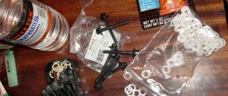
Before installing the cylinder head, perform the following steps: clean the threaded holes, as well as all holes for the bushings (photo 1). Each bushing is installed in place, and only then a gasket is placed on top.
Metal parts adjacent to the gasket must be degreased. We looked at the cylinder head tightening diagram, but the cylinder head itself must be installed correctly:
- We place the cylinder head on the cylinder block;
- By moving the part in different directions, we ensure that the bushings fit into the recesses.
After “step 2” the screws can be tightened.
Sealant
No sealing compounds are used when installing the gasket! Solidol, CIATIM and other lubricants are not even needed. The main thing is that the metal must be degreased. And the cylinder head gasket must be new.
Cylinder head cover and tightening order of its bolts
The metal cover installed on the cylinder head must not allow air to pass through. At points of contact with other parts, tightness must also be maintained. Therefore, sealant is applied to the edge of the lid. An example is shown in the photo.
Cylinder head cover before installation
Here you need to use materials: Loctite-574, ANACROL, etc. The screws on the cover are tightened with an “8” key.
Recommended screw tightening torque
The recommended screw tightening torque is only 3-4 N*m. Don't be surprised: the sealant will do its job. You just need to let it dry after putting the cover in place.
You can unscrew the screws in any order. Their number is 15 or 14. When installing, it is better to follow the sequence shown below.
The order of tightening the cap is marked with numbers and arrows
There is usually no need to replace the screws - the load is too small. We wish you success.
Common Misconceptions
If the bolts are pulled out too much, they are tightened in four steps. At “step 2” the tightening torque will be 70-85 N*m. All of these are common misconceptions that do not apply to 16-valve internal combustion engines.
Tightening torques for threaded connections
| Detail | Thread | Tightening torque, N m (kgf m) |
| Engine | ||
| Cylinder head bolt (cylinder head bolt) | M12x1.25 | see note 2 at bottom of page |
| Nut of the stud securing the intake pipe and exhaust manifold | M8 | 20,87–25,77 (2,13–2,63) |
| Tension roller nut | M10×1.25 | 33,23–41,16 (3,4–4,2) |
| Camshaft bearing housing stud nut | M8 | 18,38–22,64 (1,87–2,31) |
| Camshaft pulley bolt | M10 | 67,42–83,3 (6,88–8,5) |
| Accessory housing mounting bolt | M6 | 6,66–8,23 (0,68–0,84) |
| Nut of the stud securing the exhaust pipe of the cooling jacket | M8 | 15,97–22,64 (1,63–2,31) |
| Main bearing cap bolt | M10x1.25 | 68,31–84,38 (6,97–8,61) |
| Oil sump bolt | M6 | 5,15–8,23 (0,52–0,84) |
| Connecting rod cap bolt nut | M9x1 | 43,32–53,51 (4,42–5,46) |
| Flywheel bolt | M10x1.25 | 60,96–87,42 (6,22–8,92) |
| Coolant pump mounting bolt | M6 | 7,64–8,01 (0,78–0,82) |
| Crankshaft pulley bolt | M12x1.25 | 97,9–108,78 (9,9–11,1) |
| Coolant pump inlet pipe mounting bolt | M6 | 4,17–5,15 (0,425–0,525) |
| Muffler exhaust pipe fastening nut | M8×1.25 | 20,87–25,77 (2,13–2,63) |
| Nut securing the flange of the additional muffler | M8×1.25 | 15,97–22,64 (1,63–2,31) |
| Nut securing the clutch cable to the engine bracket | M12x1 | 14,7–19,6 (1,5–2,0) |
| Front engine mount bracket bolt | M10x1.25 | 32,2–51,9 (3,3–5,5) |
| Front engine mount bolt nut | M10 | 41,65–51,45 (4,25–5,25) |
| Nut of the bolt securing the left suspension support of the power unit | M10 | 41,65–51,45 (4,25–5,25) |
| Nut securing the bracket of the left suspension support of the power unit | M10 | 31,85–51,45 (3,25–5,25) |
| Bolt securing the rear suspension support of the power unit | M10x1.25 | 27,44–34 (2,8–3,47) |
| Nut of the power unit rear suspension bracket mounting bolt | M12 | 60,7–98 (6,2–10) |
| Bolt securing the oil receiver to the main bearing cover | M6 | 8,33–10,29 (0,85–1,05) |
| Bolt securing the oil receiver to the pump | M6 | 6,86–8,23 (0,7–0,84) |
| Oil pump mounting bolt | M6 | 8,33–10,29 (0,85–1,05) |
| Oil pump housing bolt | M6 | 7,2–9,2 (0,735–0,94) |
| Oil pump pressure reducing valve plug | M16x1.5 | 45,5–73,5 (4,64–7,5) |
| Oil filter fitting | M20×1.5 | 37,48–87,47 (3,8–8,9) |
| Oil pressure warning light sensor | M14x1.5 | 24–27 (2,45–2,75) |
| Carburetor mounting nut | M8 | 12,8–15,9 (1,3–1,6) |
| Cylinder head cover nut | M6 | 1,96–4,6 (0,2–0,47) |
| Clutch | ||
| Nut securing the clutch housing to the engine block | M12x1.25 | 54,2–87,6 (5,53–8,93) |
| Bolt securing the clutch housing to the engine block | M12x1.25 | 54,2–87,6 (5,53–8,93) |
| Clutch release bearing guide flange bolt | M6 | 3,8–6,2 (0,39–0,63) |
| Bolt securing clutch housing to flywheel | M8 | 19,13–30,9 (1,95–3,15) |
| Nut securing the clutch housing to the gearbox | M8 | 15,7–25,5 (1,6–2,6) |
| Bolt securing the bottom cover to the clutch housing | M6 | 3,8–6,2 (0,4–0,6) |
| Transmission | ||
| Conical screw for fastening the drive rod joint | M8 | 16,3–20,1 (1,66–2,05) |
| Gear selector mounting bolt | M6 | 6,4–10,3 (0,65–1,05) |
| Shift Lever Housing Bolt | M8 | 15,7–25,5 (1,6–2,6) |
| Nut securing the drive rod and torque rod clamp | M8 | 15,7–25,5 (1,6–2,6) |
| Nut of the rear end of the primary and secondary shafts | M20x1.5 | 120,8–149,2 (12,3–15,2) |
| Reversing light switch | M14x1.5 | 28,4–45,3 (2,9–4,6) |
| Bolt securing the forks to the rod | M6 | 11,7–18,6 (1,2–1,9) |
| Differential driven gear bolt | M10x1.25 | 63,5–82,5 (6,5–8,4) |
| Speedometer drive housing fastening nut | M6 | 4,5–7,2 (0,45–0,73) |
| Gear selector shaft mounting bolt | M6 | 11,7–18,6 (1,2–1,9) |
| Nut securing the rear cover to the gearbox housing | M8 | 15,7–25,5 (1,6–2,6) |
| Reverse fork clamp plug | M16×1.5 | 28,4–45,3 (2,89–4,6) |
| Conical screw for fastening the gear selector rod lever | M8 | 28,4–35 (2,89–3,57) |
| Clutch housing and gearbox mounting bolt | M8 | 15,7–25,5 (1,6–2,6) |
| Drain plug | M22x1.5 | 28,7–46,3 (2,9–4,7) |
| Front suspension | ||
| Nut securing the upper support to the body | M8 | 19,6–24,2 (2–2,47) |
| Nut securing the ball pin to the lever | M12x1.25 | 66,6–82,3 (6,8–8,4) |
| Nut of the eccentric bolt securing the telescopic strut to the steering knuckle | M12x1.25 | 77,5–96,1 (7,9–9,8) |
| Bolt securing the telescopic strut to the steering knuckle | M12x1.25 | 77,5–96,1 (7,9–9,8) |
| Bolt and nut securing the suspension arm to the body | M12x1.25 | 77,5–96,1 (7,9–9,8) |
| Extender fastening nut | M16x1.25 | 160–176,4 (16,3–18) |
| Bolt and nut securing the stabilizer bar to the arm | M10x1.25 | 42,1–52,0 (4,29–5,3) |
| Nut securing the stabilizer bar to the body | M8 | 12,9–16,0 (1,32–1,63) |
| Bolt securing the brace bracket to the body | M10x1.25 | 42,14–51,94 (4,3–5,3) |
| Nut securing the telescopic rod rod to the upper support | M14x1.5 | 65,86–81,2 (6,72–8,29) |
| Bolt securing the ball joint to the steering knuckle | M10x1.25 | 49–61,74 (5,0–6,3) |
| Rear wheel hub bearing nut | M20x1.5 | 186,3–225,6 (19–23) |
| Front wheel hub bearing nut | M20x1.5 | 225,6–247,2 (23–25,2) |
| Wheel bolt | M12×1.25 | 65,2–92,6 (6,65–9,45) |
| Rear suspension | ||
| Nut securing the lower end of the shock absorber | M12x1.25 | 66,6–82,3 (6,8–8,4) |
| Rear suspension arm mounting nut | M12x1.25 | 66,6–82,3 (6,8–8,4) |
| Nut for securing the suspension arm brackets | M10x1.25 | 27,4–34 (2,8–3,46) |
| Nut securing the upper end of the shock absorber | M10x1.25 | 50–61,7 (5,1–6,3) |
| Brakes | ||
| Bolt securing the brake cylinder to the caliper | M12x1.25 | 115–150 (11,72–15,3) |
| Bolt securing the guide pin to the cylinder | M8 | 31–38 (3,16–3,88) |
| Brake to steering knuckle bolt | M10x1.25 | 29,1–36 (2,97–3,67) |
| Rear brake to axle bolt | M10x1.25 | 34,3–42,63 (3,5–4,35) |
| Nut securing the vacuum booster bracket to the bracket booster | M8 | 9,8–15,7 (1,0–1,6) |
| Nut securing the master cylinder to the vacuum booster | M10 | 26,5–32,3 (2,7–3,3) |
| Nut securing the vacuum booster to the bracket booster | M10 | 26,5–32,3 (2,7–3,3) |
| Brake pipe connection nut | M10 | 14,7–18,16 (1,5–1,9) |
| Front brake flexible hose end | M10x1.25 | 29,4–33,4 (3,0–3,4) |
| Steering | ||
| Steering gear housing mounting nut | M8 | 15–18,6 (1,53–1,9) |
| Steering shaft bracket mounting nut | M8 | 15–18,6 (1,53–1,9) |
| Steering shaft bracket mounting bolt | M6 | Screw until the head comes off |
| Bolt securing the steering shaft to the gear | M8 | 22,5–27,4 (2,3–2,8) |
| Steering wheel nut | M16x1.5 | 31,4–51 (3,2–5,2) |
| Tie rod end coupling bolt | M10 | 19,1–30,9 (1,95–3,15) |
| Ball stud fastening nut | M12x1.25 | 27,05–33,42 (2,76–3,41) |
| Bolt securing the steering linkage to the rack | M10x1 | 70–86 (7,13–8,6) |
| Steering gear bearing nut | M38x1.5 | 45–55 (4,6–5,6) |
| Electrical equipment | ||
| Spark plug | M14x1.25 | 30,67–39 (3,13–3,99) |
| Generator mounting bolt nut | M12x1.25 | 58,3–72 (5,95–7,35) |
| Generator mounting stud nut | M10x1.25 | 28,08–45,3 (2,86–4,62) |
Notes: 1. The given torque values can be rounded to tenths within tolerance. 2. The cylinder head mounting bolts must be tightened in four steps: 1 – to a torque of 20 Nm (2 kgf); 2 – torque 69.4–85.7 (7.1–8.7 kgf); 3 – turn 90°; 4 – turn it 90° again.
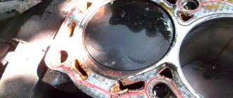
Cylinder block and connecting rod-piston group (SHPG)
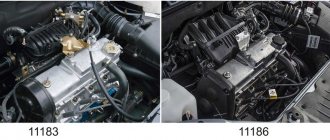
This is the main part of the engine in which the energy of burned fuel is converted into mechanical energy. It consists of a cylinder block, pistons, connecting rods, connecting pins of support bearings, a crankshaft and half rings that limit the displacement of the latter relative to its axis.
The VAZ 21124 engine with 16 valves is equipped with a “high” block 11193, which received its nickname due to its size. It is cast from cast iron, and then it is machined to accommodate the cylinders. Its height is 197 millimeters (from the axis of rotation of the crankshaft to the top edge). It is 2.2 mm higher than the cylinder block used in the 21120 engine. This increase allowed the displacement to be increased to 1.6 liters without increasing the cylinder diameter. The block is also distinguished by a reduced size of the holes for the cylinder head mounting bolts.
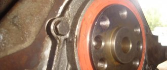
The crankshaft (catalog number - 11183 -1005016), like the block, is cast from cast iron. The journals (points of contact with other parts) are polished and holes are drilled in them to lubricate the support and connecting rod bearings. To reduce vibration from rotation, 8 counterweights are installed on the shaft, shaped like half a disk.
The connecting rods are forged from steel and consist of two heads - upper and lower. At the top there is a bushing made of steel-bronze alloy for attaching the piston. Liners (sliding bearings) are pressed into the lower one. The connecting rod is attached to the crankshaft using a cover and 2 bolts.
The pistons installed in the VAZ 21124 16 valve engine were developed specifically for it. They are cast from aluminum, and at their end there are 3 grooves for installing 2 compression rings and one oil scraper ring. There are 4 recesses 5.5 millimeters deep on the piston bottom (the side in contact with the valves)
This measure adds another important property to the engine - the safety of the valves in the event of a timing belt break or improper installation. For this modification, the owners call the motor “plugless”
The pistons are cooled using oil nozzles installed in the main bearing supports.
Severe wear of this part of the engine leads to a severe deterioration in the performance of the VAZ 21124 engine, up to the impossibility of starting.
In what cases is it necessary to tighten the block?
Tuned VAZ 2112 car with a 16-valve engine
Before you begin this process, you need to understand what this node is. The cylinder head on a VAZ can be made of aluminum or cast iron. In essence, it is the top cover of the engine. As for its functions, it performs the following options:
- protective, since it protects the motor from external influences;
- functional, since important elements work in the cylinder head, such as support washers, valve bushings, etc.;
- There is also a hole in the cylinder head where the chain tensioner and camshaft pulley drive are installed.
The tightening torque of the VAZ 2112 cylinder head bolts must always be set correctly. Because this is necessary primarily to prevent moisture from occurring in the place where these components are connected. And moisture and condensation, in turn, collect in the plane due to leakage of motor fluid.
Work execution algorithm
The tightening procedure is the same for all cars, regardless of the number of valves and the presence of front or rear wheel drive.
Proceed like this:
- prepare the tools;
- inspect the removed head and be sure to inspect the surface of the block itself;
- clean the surfaces from dust and degrease;
- make sure that there is no debris in the mounting holes (if necessary, blow them out with a compressor);
- install the gasket;
- place the head on it;
- wipe the bolts themselves with lubricant;
- screw them in by hand;
- Tighten in the order described above.
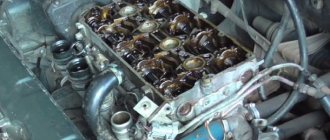
Tightening process and diagram (on a 16 valve car)
16 valve engine of the VAZ 2112 car
But while you have not yet begun the procedure for tightening the cylinder head pins, you need to emphasize that each engine has its own torque and tightening pattern. As you might have guessed, this point will be different for each vehicle. In addition, several factors directly influence the torque indicator, and if you decide to engage in this process yourself, then it will be useful for you to learn about them:
- The tightening torque of the head is affected by the lubrication of the holes for the pins, as well as their condition, and, of course, the quality of the bolts themselves. In order for the torque to be set correctly, both the pins and the holes for them must be lubricated, and regular motor oil will do for this.
- If the thread of the hole or the pin itself is deformed, then it is better to refrain from the tensioning procedure. One way or another, over time this will lead to negative consequences.
If you are the owner of a VAZ 2112 with a 16-valve engine and are faced with the need to tighten bolts, our website will help you with this. This will be especially necessary in cases where the block head was dismantled and reinstalled. What is the tightening torque and how does the procedure take place? Next, we will consider this process step by step for a VAZ 2112 with a 16-valve engine.
Required Tools
And, although this procedure requires a certain approach, its preparation will not take much time. The bottom line is that a large set of tools is not required directly to tighten the head pins. The only thing you need is some motor fluid and a special torque wrench.
Torque wrench for work on a 16-valve engine
If you do not have such a key, then you need to buy it in advance or borrow it from a car service center. You need just such a tool, since it allows you to determine exactly the tension moment. Currently, a more budget version of this tool costs about 200-250 hryvnia (600-800 rubles).
Possible consequences
Leakage of lubricant through the oil seal is not dangerous only for the time being:
- Don’t forget about the dangers to the engine of oil leakage from the lubrication system: firstly, increased wear due to the parts running dry, and secondly, oil consumption for topping up, the price of which is also a pretty penny
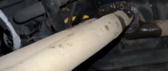
- The timing belt can jump over a pulley tooth and even several teeth at once, all due to oil getting on the belt teeth caused by leaking camshaft oil seal, which causes an oil film to form on the timing belt
- If lubricant gets in (lubricant is a chemical), the belt begins to spread and can break under load at full speed of the car, you can imagine the consequences
- Therefore, if even minor oil stains are detected on the timing belt casing, it is necessary to immediately determine the cause of the stain.
A little about what an oil seal is in general:
An oil seal is a rubber-metal cuff that serves to seal the rotating parts of units and prevents liquids (lubricants) from leaking out of them. The name “seal” comes from ancient cars, where instead of a cuff, felt lubricated with lard (grease) was used. The cuff has a special edge, which when rotated creates a turbulence that prevents lubricant from flowing out of the unit. It is important not to confuse the direction of rotation (there are left and right cuffs), otherwise a new ideally installed cuff will leak
This is interesting: How to close the starter directly on a VAZ-2114 - photo and video
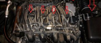
Engine lubrication system design
Let's look at the purpose and operation of individual nodes.
- The oil pump builds up pressure in the lines, with its help the liquid enters the oil filter from the sump, and is distributed throughout the system in a purified form. The pump is connected to the engine crankshaft and runs immediately after starting.
- Drain hole for draining the crankcase when changing the oil.
- The oil intake is a socket through which liquid is sucked into the pump. Located in the lower part of the crankcase to prevent oil starvation when the level drops.
- The bypass valve returns lubricant to the oil pan if the passage of a dirty filter interferes with normal circulation.
- Spray points on working units (original nozzles for creating oil mist). When the spray points become clogged, the lubrication regime is disrupted, so there should be no insoluble debris in the liquid (it remains in the filter cartridge).
- Oil line. It can be made in the form of tubes or special channels in the engine housing. Slag deposits interfere with the patency of the channels, so detergent additives are added to the lubricant.
- Filler neck (shown conditionally). It is used to top up or replace fluid.
- Oil radiator valve (tap). In summer it opens for additional cooling.
- Lubricant cooling radiator. Not present in all car models.
- Oil filter. It is a metal cylinder that can withstand high pressure. Inside there is a filter cartridge made of special paper or synthetic materials.
To monitor the state of the system, a number of sensors are integrated into it:
- temperature;
- pressure;
- in some designs - level;
- filter cleanliness (the same pressure sensor, only located directly on the flange of the filter element).
During normal operation, the engine maintains constant pressure. Malfunction of the system leads to a sharp increase in wear, temperature of parts, and engine jamming.
Please note As can be seen from the operating diagram, replacing oil with “magic” additives, which supposedly allow you to work “dry”, cannot provide all the functionality of the fluid. Therefore, you should not experiment with such chemistry