The crankshaft is one of the most important parts of any engine. It is strictly individual for each car model and during operation it is ground into a specific engine.
What is a crankshaft and its main tasks?
The crankshaft (crankshaft) is the main element of a car engine, being part of the crank mechanism, which converts the energy of gases burned in the engine cylinders into mechanical energy.
The main task of the crankshaft is to convert the reciprocating movements of the engine pistons into torque, which is transmitted through the transmission to the wheels of the car. One of the main technical characteristics of the crankshaft, like the entire engine, is the radius of the crank. This is the distance from the axes of the main journals (the journals in which the crankshaft rotates in the cylinder block) to the axes of the connecting rod journals (the journals that rotate inside the large head of the connecting rod). The double radius of the crank is the length of the piston stroke, which determines the volume of the cylinders. If you change the length of the crank radius while keeping the cylinder diameter constant, this will lead to a change in the volume of the cylinders. This relationship is often used to change the technical characteristics of the entire engine in a certain direction.
By selecting the ratio of the piston stroke length to the cylinder diameter, the engine can be made long-stroke (the piston stroke exceeds the cylinder diameter) or short-stroke (the cylinder diameter is larger than the piston stroke). Short-stroke engines make it possible to increase power by increasing rotation speed. And long-stroke engines are more economical and provide high torque at low speeds.
When changing the parameters of the crankshaft, all engine parameters change, so you need to be extremely careful when tuning your car, since technical characteristics often change not for the better.
Materials from which the crankshaft is made
When the engine is running, heavy loads are applied to the crankshaft. Its reliability is determined by its design and the material from which it is made. This engine element, as a rule, has a solid structure. Therefore, the materials for it must be as durable as possible, because the operation of the entire system will depend on the strength of the crankshaft.
Carbon and alloy steel or high-strength cast iron are used as materials for the manufacture of crankshafts. The crankshaft can be manufactured by casting, steel forging or turning. Blanks are produced by hot stamping or casting. It is very important how the fibers of the materials are arranged in the workpieces. To prevent them from being cut during further processing, bending strands are used. When the workpiece is ready, it is additionally processed at high temperature and cleaned of scale (with a shotgun or by etching).
The material and production method of the crankshaft are selected depending on the type and class of the car.
1. In production models, the crankshaft is made from cast iron. This makes it possible to reduce production costs and meet the specified calculations.
2. More expensive sports models are equipped with a forged steel crankshaft. Such parts have many advantages over cast ones in terms of size, weight and strength, and therefore are increasingly used in the automotive industry.
3. For the most expensive engines, the crankshaft is machined from a single piece of steel. In this case, a significant part of the material simply becomes waste.
Crankshaft design
The design of the crankshaft is determined by the number of cylinders, their configuration and operating order, which determines the location and number of main and connecting rod journals. For example, in V6 engines there is a slight angular displacement of the crankpins along the length of the shaft. The American version of the V8 engine has a cross-shaped crankshaft, while the European version of the sports car V8 has a flat crankshaft. Despite all this, the design of different crankshafts is very similar. Structurally, the crankshaft consists of the following basic elements:
1. Main journals - the support journal, which is located in the main bearing (located in the engine crankcase).
2. Connecting rod journals - support journals that connect the crankshaft to the connecting rods (oil channels for lubrication pass through them) and serve as a support for the connecting rods.
3. Shaft cheeks - an element that connects the main and connecting rod journals.
4. Toe (output front part of the shaft) - the part on which the gear wheel or power take-off pulley is attached, connecting to the gas distribution mechanism, camshaft, torsional vibration damper, auxiliary components and elements.
5. Tail (output rear part of the shaft) - the part that connects to the flywheel or power take-off gear.
6. Counterweights - an element of the crankshaft (essentially, an extension of the crank in the opposite direction from the crankpins), which is responsible for unloading the main journals from the inertia forces of the lower parts of the connecting rods and the unbalanced masses of the crank and ensure smooth operation of the engine.
7. Sliding bearings – ensure rotation of the crankshaft on supports. The bearings are thin-walled liners made of steel tape with an anti-friction layer. The earbuds are fixed in the support with a protrusion that prevents them from twisting or due to a tight fit. The presence of lubrication ensures easy rotation in the bearings for a long time.
8. Thrust bearing is an element that does not allow axial movements of the crankshaft. It is installed on the outer main journal or on the middle main journal. The number of main journals usually exceeds the number of connecting rods by one (such a crankshaft is called full-support) and they have a larger diameter.
We recommend: Car wheels and tires. Their structure and markings
The knee is the connecting rod neck, which is located between the two cheeks. The position of the knees is determined by the operating characteristics of the engine, the position of its cylinders and should ensure its balance, minimal vibrations and minimal torques.
The junction of the neck to the cheek is the most loaded place in the crankshaft design.
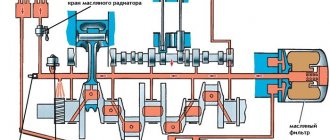
In order to reduce the stress on this place, the transition is made with a fillet (radius of curvature). The fillets increase the length of the shaft and, to reduce this value, they are deepened into the journal or cheek. All main and connecting rod journals are integrated into the engine lubrication system. These elements are lubricated under pressure. The oil supply is organized to each of the main journals from the common line on an individual basis. And the oil gets to the connecting rod journals through the channels in the cheeks.
Crankshaft Maintenance
The crankshaft, like any car part, requires periodic maintenance. To do this, you need to be able to remove it and install it back.
The crankshaft is removed in the following sequence:
1. The engine is removed from the car, and then all elements are removed from it.
2. The engine is turned over with the crankshaft facing up. The main bearing caps are different, so you need to remember their position.
3. The main bearing caps are removed.
4. The crankshaft is raised and the rear O-ring is removed.
5. The main bearings are removed from the main bearing caps and the cylinder block.
After removal, the crankshaft is checked.
Algorithm for checking the crankshaft:
1. Wash all components with gasoline and dry the part.
2. Carefully inspect the crankshaft for any negative signs of use (cracks, chips, severe wear). If the crankshaft is found unsuitable for further use, then you will have to purchase a new one.
3. Clean, rinse and blow out all oil channels with compressed air, after unscrewing the plugs.
4. If burrs or scratches are found on the connecting rod journals, they must be ground and polished. After this, the oil channels should be blown out with air again.
5. Inspect the main bearing shells. If they have defects, they must be replaced with new ones.
6. Inspect the flywheel and if defects are found on it, the flywheel should be replaced.
7. Inspect the sock bearing and, if it has negative traces of use, then it needs to be pressed out and a new one pressed in.
8. Inspect the oil seal located in the timing sprocket cover and, if necessary, replace this part. If the car has a high mileage, the oil seal must be changed.
9. Replace and compress the crankshaft rear seal packing.
10. Check the rubber seals located in the packing holder. If they are unsuitable for further use, they must be replaced.
After checking, the crankshaft must be reinstalled. Installation of the crankshaft is carried out in the reverse order to its removal. Before installation, be sure to lubricate all journals and other crankshaft elements with engine oil. After installation, check that the crankshaft rotates easily and smoothly. Otherwise, you will have to remove it again and reinstall it, achieving a smooth ride.
Subscribe to our feeds on social networks such as Facebook, Vkontakte, Instagram, Pinterest, Yandex Zen, Twitter and Telegram: all the most interesting automotive events collected in one place.
What is the crankshaft for?
Any car engine is a piston engine. The principle of its operation is simple: a fuel-air mixture is supplied to the cylinder, which ignites and increases in volume. Excess pressure arises, which pushes the piston out of the cylinder. At the same time, the piston makes a translational movement, which must be converted into a rotational movement in order to transmit it to the gearbox, and then to the axle shaft or driveshaft.
This is precisely the function that the crankshaft performs - it converts one type of mechanical movement into another, namely: translational into rotational.
The material from which crankshafts are made is not simple steel, which is why the cost of the product is so high compared to the price of a simple metal blank. The steel from which the shaft is made is alloyed with chromium, molybdenum and other metals, which gives the product special strength. In addition, the manufacturing process itself is important, starting from how the fibers of the workpiece are arranged, ending with the manufacturing method - pressing or forging.
We figured out what the shaft does, but the question remains - where is the crankshaft? The crankshaft is located at the bottom of the engine, covered from below by a crankcase filled with engine oil. The shaft is secured in bearings that hold it and do not allow it to move; sometimes additional stops are used to strengthen it. But there is an exception - in boxer engines the crankshaft is located higher, in the center of the internal combustion engine.
The pistons in the engine move unevenly - while the days are falling, others are rising - this ensures smooth running and even distribution of the load over time. The crankshaft restrains the stroke of the pistons after fuel combustion and returns them to their original position to compress the mixture. On the one hand, it is connected to the gas distribution mechanism, on the other, it transmits torque to the transmission.
The crankshaft consists of several journals:
- The main ones are located exactly along the central axis of the shaft and do not shift during rotation.
- Between them there are connecting rod journals, which are offset relative to the axis at different, strictly defined angles, and when rotated, describe a circle. They are the ones who ensure the interaction between the shaft and the piston.
- The necks are connected to each other by “cheeks” - plates made of thick metal. The cheeks, in addition to the fastening ones, perform an anti-resonance function - during rotation, the shaft can resonate and collapse, but the cheeks do not allow this to happen.
We recommend: Mixing antifreeze of different standards and colors
It is difficult to describe the appearance of this part in words, but if you want to accurately represent the crankshaft, a photo or diagram is the best option.
Operating principle of the crankshaft:
- At the moment when the air-fuel mixture ignites in the chamber, the piston, and accordingly the neck associated with it, are in the lowest position.
- When the mixture ignites, the piston pushes out the neck, which moves and thereby rotates the shaft.
- In turn, another neck, offset relative to the one described, rotates under the influence of rotational torque and presses the piston associated with it into the cylinder, compressing the fuel-air mixture.
Then everything continues in the same way. This is a simple sign; do not forget that a car engine is a four-stroke engine, so at a certain moment the piston is in one of the following positions:
- Mixture inlet.
- Compression of the mixture.
- Piston stroke.
- Exhaust gas release.
Therefore, each of the connecting rod journals is located at an angle of 90 degrees compared to the adjacent ones.
Some interesting information about crankshafts
Grinding the crankshaft
In addition to the usual serial ones, there are sports crankshafts. They provide faster piston travel at the extreme point of compression due to the special shape of the connecting rod journals. If on a regular shaft they have a round shape, then on a sports shaft they are slightly elongated, due to which the overall characteristics of the engine change.
There is an opinion among motorists that the marking of the crankshaft can tell about its characteristics. In fact, this is not so - the marking is just the manufacturer's catalog number or the original number. It has nothing to do with the properties of the product, but is used to simplify the selection of spare parts.
Essentially, a crankshaft is a simple piece of properly processed high-quality metal or alloy. From a functionality point of view, this is an irreplaceable part that experiences enormous loads, the operation of which determines not only the ride quality, but also the life of the engine and its parts. In fact, it is simply a transmission link that ensures the operation of other components of the car - the generator, transmission, axle shafts, driveshaft, and so on.
The crankshaft is one of the main elements of the engine. It is part of the crank mechanism. It has a complex structure. What is this mechanism? Let's consider.
Device and purpose
The crankshaft receives the forces from the piston and converts them into mechanical energy. This mechanism is affected by rotational forces. It works constantly under high load. Therefore, to prevent the part from failing prematurely, crankshafts are made of high-quality, high-strength cast iron alloys. Then all parts are hardened with high frequency current. There are shafts with double counterweight or no counterweight at all. The engine cam is located directly in the motor housing.
As for the design, it generally depends on the engine. Despite some differences, the designs have a lot in common. The crankshaft is a complex of several parts. Main journals are used as support for this structure - models with four journals are more common, but there are also three-legged ones. Six-cylinder engines have shafts with 7 such supports. In order for the crankshaft to be balanced, counterweights are used. If the cylinders have a small diameter, then single counterweights are used. These parts ensure the smoothest operation of the power unit.
The crankshaft is removed in the following sequence:
1. The engine is removed from the car, and then all elements are removed from it.
2. The engine is turned over with the crankshaft facing up. The main bearing caps are different, so you need to remember their position.
3. The main bearing caps are removed.
4. The crankshaft is raised and the rear O-ring is removed.
5. The main bearings are removed from the main bearing caps and the cylinder block. After removal, the crankshaft is checked.
Algorithm for checking the crankshaft:
1. Wash all components with gasoline and dry the part.
2. Carefully inspect the crankshaft for any negative signs of use (cracks, chips, severe wear). If the crankshaft is found unsuitable for further use, then you will have to purchase a new one.
3. Clean, rinse and blow out all oil channels with compressed air, having previously unscrewed the plugs.
4. If burrs or scratches are found on the connecting rod journals, they must be ground and polished. After this, the oil channels should be blown out with air again.
5. Inspect the main bearing shells. If they have defects, they must be replaced with new ones.
6. Inspect the flywheel and if defects are found on it, the flywheel should be replaced.
7. Inspect the sock bearing and, if it has negative traces of use, then it needs to be pressed out and a new one pressed in.
8. Inspect the oil seal located in the timing sprocket cover and, if necessary, replace this part. If the car has a high mileage, the oil seal must be changed.
9. Replace and compress the crankshaft rear seal packing.
10. Check the rubber seals that are located in the packing holder. If they are unsuitable for further use, they must be replaced.
After checking, the crankshaft must be reinstalled. Installation of the crankshaft is carried out in the reverse order to its removal. Before installation, be sure to lubricate all journals and other crankshaft elements with engine oil. After installation, check that the crankshaft rotates easily and smoothly. Otherwise, you will have to remove it again and reinstall it, achieving a smooth ride.
Crankshaft grinding
The crankshaft is a very expensive thing, however, due to friction, it becomes unusable over time. In order not to buy a new one, it is polished. This work can only be performed by highly qualified turners who have the appropriate equipment. You will also need to purchase a set of repair connecting rod and main bearings. Inserts are sold in almost any spare parts store and go under the designations: N (nominal size) - correspond to the parameters of the new crank; P (P1, P2, P3) - repair liners, their diameter is several millimeters larger. Based on the size of the repair liners, the machinist accurately measures the diameter of the journals and adjusts them to the new liners. For each model, the pitch of the repair inserts is determined.
We recommend: Window lift motor - how does it work?
Crankshaft faults and how to solve them?
Crankshaft operation
it is designed in such a way that most often it breaks, since the lubrication of parts worsens due to increasing gaps between the liner. Also, problems with the operation of the crankshaft can arise due to insufficient pressure in the lubrication system or the use of low quality oil.
Main crankshaft defects:
- Scuffing of the journals
of the part, which causes an increase in the opening in the bearing; - Wear of the surface
of a part with a deep ring risk; - Overheating and melting of the crankshaft liners
(less likely to happen);
The main problem with the crankshaft is journal scuffing.
.
- Crankshaft key
cut. Such a defect can be eliminated by welding and a milling cutter. - Wear of the shaft flange holes
for the flywheel mounting bolts. In this case, they are processed by reaming to the repair size, assembled with the flywheel. - Inappropriate handling of the part
and
untimely replacement of oil seals
are other breakdowns that can occur with the crankshaft.
Such malfunctions can lead to very serious defects, including cracks in the part.
To eliminate wear and scuffing of the crankshaft, you will need to grind the journals and bring them to good condition. In this case, the following problem may arise: scuffing will contribute to heating of the entire surface of the neck, as a rule, the temperature rises to hundreds of degrees. The side of the neck that takes the heaviest load will, accordingly, heat up to the maximum temperature, which means that the knee will be subject to deformation and the crank cheeks will be compressed. The rotation axis and the elbow will bend, as a result of which the axis of the main journals will be disrupted and the part will be bent. In this case, in order to repair the crankshaft, you will need to use a number of additional procedures to correct the problems. Re-growing the crankshaft to the next size and installing new bearings.
So, we see that the crankshaft of a car is the inner part of the “heart” and the quality of the part, as well as proper care, significantly influence the service life. Long-term operation of the crankshaft directly depends on the condition of the main and connecting rod journals, bearings and the quality of the lubrication system.
Crankshaft
Rice. V6 engine crankshaft
The crankshaft receives the forces transmitted from the pistons by the connecting rod and converts them into torque. Therefore, the crankshaft must be strong and rigid. High-strength cast iron and steel are used as the material for the crankshaft. Cast iron shafts are made by casting, while steel shafts are made by forging. The working surfaces of the main and connecting rod journals of the crankshaft are subjected to hardening using heat treatment and subsequent grinding. The crankshaft consists of several main journals connected by cheeks to the connecting rod journals. The crankshaft cheeks continue in the opposite direction from the journal, forming counterweights. Some truck engines use removable counterweights that are bolted to the crankshaft. Main journals are always larger in diameter than connecting rod journals. The crankshaft will be stiffer if the main and connecting rod journals overlap each other when viewed from the end of the shaft. Obviously, it is much easier to achieve journal overlap in a [[Short-stroke engine|short-stroke engine]]. If there are main journals on both sides of the crankpin, the crankshaft is a full-support crankshaft.
.
Otherwise, it is not fully supported
and therefore must be more rigid, and therefore more massive, in order to absorb significant bending and twisting forces.
Therefore, modern engines mainly use full-support shafts. Nowadays, collapsible crankshafts are rarely used, although this shaft design makes it possible to use connecting rods with a one-piece lower head. The transition from the neck to the cheek is dangerous from the point of view of stress concentration, and therefore it is performed along a radius. This design reduces the possibility of cracks and subsequent fatigue fracture. Split, thin-walled liners are currently used as main and connecting rod bearings
.
The liners are made of steel tape coated with a layer of anti-friction alloy. To ensure that the installed liners do not rotate in the crankshaft supports and connecting rod heads, they have a protrusion with which they are fixed in the corresponding grooves. To protect the crankshaft from axial movements, thrust plain bearings are used. Holes for oil passage are drilled inside the crankshaft, in the cheeks and journals of the crankshaft. The crankshaft bearings are subject to significant loads, and even short-term operation of the engine without oil leads to its failure, so oil is constantly supplied to the crankshaft journals under pressure. A flywheel
is attached to the rear end of the crankshaft . The flywheel serves to reduce the unevenness of engine operation, storing energy during the power stroke and releasing it during other strokes, and also removes the crankshaft from dead spots. The flywheel is a massive disk made of cast iron. A ring gear is pressed onto the outer cylindrical surface of the flywheel, ensuring rotation of the crankshaft when starting the engine using an electric starter. In multi-cylinder engines, the power stroke occurs simultaneously in several cylinders. With such engines, the torque is more uniform and the flywheel mass can be reduced.
Rice. Dual mass flywheel
No matter how rigid the crankshaft is, it is subject to torsional vibrations. Torsional vibrations
can be represented as constant twisting followed by unwinding of the shaft, which occurs when the engine operates at a certain frequency.
When the frequency of torsional vibrations coincides with the frequency of external forces, resonance may occur, which will lead to a sharp increase in the loads acting on the crankshaft and, as a consequence, to its breakdown. Fracture of crankshafts (usually at the junction of the journal and main journal) was a common cause of failure in older engine designs. Modern crankshafts have high rigidity, and the resonant frequencies are beyond the possible speeds of the shafts of these engines. Nevertheless, in the design of engines, torsional vibration dampers
, which reduce the vibration activity of the crankshaft to the desired level. The most common method is to separate the pulley or disk mounted on the crankshaft into an inner and outer part and connect them with an elastic material that absorbs vibrations due to internal friction. Nowadays, dual-mass flywheels are becoming increasingly common, which successfully serve as a torsional vibration damper. Advances in control systems may bring further changes to engine design. Today, new toroidal starter-generators have been developed that not only instantly and silently start the engine, but also make it possible, through electronic control, to dampen all kinds of oscillations and vibrations, and also provide the ability to operate the engine under extreme loads.
Crankshaft. Device and types
In an engine, all parts are equally necessary and important. If even one spare part breaks down, the entire engine fails. Today we will examine in detail the crankshaft, which converts the reciprocating movements of the connecting rods and pistons into rotational ones.
Device
The crankshaft consists of:
The crankshaft axis consists of main journals that run exactly in the center. The connecting rod journals play the role of fastening and receiving pressure from the connecting rods. The connecting rod journals are offset relative to the shaft axis and are held by the cheeks.
There are as many connecting rod journals as there are cylinders. But in many V-shaped engines, 2 cylinders rest on 1 journal. It can also be found when V-shaped engines have a crankshaft in which 1 journal is designed for 1 connecting rod, but the connected journals are then shifted by 18 degrees relative to each other.
As for the cheeks, they have several functions: they connect the journals and act as a counterweight to balance the connecting rods and crankpins. If there was no counterweight, then vibration would appear, and for high-speed internal combustion engines, this is a sure sign indicating the possibility of engine failure.
In the crankshaft, the main load is distributed on the cheeks and on the joints of the journals. To ensure uniform distribution, these segments are made with a fillet - a transition in the form of a rounded shape from the neck to the cheek.
As a result, the correct arrangement of the cheeks and journals in the crankshaft ensures the effective operation of the reciprocating motion into the rotational one: it balances the internal combustion engine, resists bending loads and prevents the occurrence of oscillations and vibrations.
Full-support and part-support crankshafts
The main journals are larger in size than the connecting rod journals, and they serve as both an axis and a support for the crank mechanism (crank mechanism). The load is transmitted to the engine from the crankshaft through the main journals, which also rest on the main bearings in the engine crankcase.
The crankshaft is divided into 2 types according to the type of support:
- Full support. It has one more main journal than connecting rod journal. The main journals are located on both sides of the connecting rod journals.
- Partially supported. There are fewer main journals than connecting rod journals, but on the sides of the cheek there may be 2 connecting rod journals offset at a specific angle.
The simple design of the part-support crankshaft, as well as the smaller number of support points, indicates a high degree of rigidity and strength, and, accordingly, heaviness. That is why in the 21st century full-support crankshafts are more often used, although they are more difficult to manufacture, but the end result is light and reliable.
Lubrication of the crankshaft and other parts of the crankshaft
Lubrication of crankshaft spare parts is very important: plain bearings (liners) are used to support the main journals and connecting rods on the connecting rod journals, and they cannot function properly without constant lubrication.
To allow oil to flow to the parts, there are channels inside the crankshaft. Thanks to the pressure, the lubricant flows evenly to the bearings.
Interaction of the crankshaft together with other spare parts
The load is applied to the crankshaft through the connecting rods, thereby translating into torque. This very moment passes through the rear part of the shaft (shank) to the flywheel and then to the transmission. Through the front part of the shaft (toe), the torque is transferred to the timing shaft and other engine systems.
Often there is a vibration damper on the toe. This simple device consists of 2 discs, a rubber gasket, connecting springs and an elastic material such as silicone fluid. Such a damper reduces torsional vibrations of the shaft when the motor is running, which minimizes the risk of damage.
Production and material
During operation, a large load is applied to the crankshaft. For diesel engines, a solid crankshaft is produced. But prefabricated crankshafts in practice turned out to be untenable for high-speed engines, and therefore they are almost never used.
The manufacturing material used is steel or cast iron. A crankshaft made of cast iron is made by casting, and a crankshaft made of steel by forging or stamping. The cast iron and steel crankshafts are then machined to achieve the desired parameters - balance, surface finish, etc.
You will find auto parts for the engine and its components on our website in the “Spare Parts Category” section.
Source
How the part is arranged
Different engines use different crankshaft shapes. For example, on V6 engines the connecting rods shift slightly in length, the American V8 is cross-shaped, and the European one is flatter.
But any crankshaft consists of several standard parts:
- main and connecting rod journals;
- connecting cheeks;
- counterweights;
- front part (toe);
- back part (shank).
Each of them performs its own function and is connected with the others.
- The main journal is the main part of the shaft, located in the crankcase on bearings.
- The connecting rod journals are offset to the side and connect the shaft to the connecting rods and have oil channels for lubrication.
- These necks are called knees, which is how the part got its name. The location of the cylinders depends specifically on the elbows, which distribute the load and regulate the movement of gas masses.
- The cheeks connect the necks to each other.
- Counterweights balance the pistons and connecting rods, and their proper functioning is key to the smooth operation of an internal combustion engine.
- The nose has a pulley, gears and a vibration damper that controls the timing mechanism.
- The shank takes power from the shaft. Connected to the flywheel using a special comb.
Outside the cylinder block, the flywheel is sealed with seals to prevent oil leakage. Sliding bearings provide rotational movements of the system.
When the gases act on the pistons, they transfer energy to the connecting rods, which are connected to the bushing or piston pin. Using a bearing, the connecting rod is attached to the crankshaft journal. Due to this, rotational movement occurs. After turning 180 degrees, the neck begins to move in the opposite direction, and the piston is returned to its original position. This ends one cycle and a new one begins.
Causes of failure
Structural damage and wear during operation are the most common reasons for replacing parts. Despite the regular supply of lubricant and careful operation of the motor, this process is inevitable. Over time, the surface of the journals becomes thinner, the free space between them becomes larger, because of this the crankshaft acquires free movement, the oil pressure decreases and, as a result, its supply decreases. All this causes premature failure of the entire engine system.
Scrolling is the second reason for repair work. Many people have heard about this or dealt with this problem on their own, but not all car owners know why this situation arises. Connecting rod bearings have thin plates that fit into a special bed. In this case, small protrusions are placed along the entire outer surface of the half rings; they should come into contact with the front part of the block, as is the case in new motors. Some conditions reduce the resistance of the antennae in relation to the liner; it sticks to the crankshaft journal and rotates. In such a situation, engine operation stops. It is worth noting the most common reasons for its development:
- the operation of the motor is associated with constant exceeding of the established loads;
- the lubricant has too liquid a structure;
- bearing caps are installed with low interference;
- lack of oil, its excessive viscosity or the presence of abrasive compounds in the composition.
Service Process
Like any part, the crankshaft requires special care. For inspection and repair, it must be removed. This is usually required during a major overhaul, for example, after a water hammer, during which the crankshaft may move.
To remove the crankshaft, it is necessary to dismantle the engine and its elements. Having turned the internal combustion engine over, mark the location of the main bearing caps, then remove them, lift the crankshaft and disconnect the rear sealing ring. After this, remove the liners from the cylinder blocks and covers. Thus, we have a disconnected crankshaft.
To check it, you need to wash the part with gasoline and dry it. An inspection is carried out for cracks, chips, and dents. If any are found, the part must be replaced.
By unscrewing the plugs, you can clean all the oil channels. The connecting rod harnesses are ground and polished, and the oil passages are cleaned again. Bearing shells, nose bearing, flywheel, oil seal and rubber seals must also be replaced if defects are detected.
After this, the engine is assembled in the reverse order of disassembly, having previously lubricated all parts. You also need to make sure that the part slides and rotates smoothly.
Interesting things about crankshafts
It is often believed that the markings on a part can tell about the characteristics. However, this is just a misconception. The marking simplifies the selection of a part, since it is a catalog number, but does not say anything about the properties of the product itself.
For sports cars, crankshafts are produced with slightly elongated journals instead of round journals. They increase the overall performance of the vehicle as the piston moves slightly faster at the end point of compression.
The crankshaft is the main transmission link, ensuring the operation of axle shafts, transmission, cardan, generator and other systems. It is able to withstand enormous loads and high temperatures, and is made from high-strength alloys. The service life of the engine depends on the quality of this part.
Do not forget that any malfunction or extraneous noise should be eliminated immediately.
You should not engage in diagnostics and repairs if you do not have the necessary skills. In order not to encounter a more serious breakdown after independently tampering with the car, you need to contact a car service center, where experienced technicians can quickly install and fix the problem.
Thermal and chemical-thermal treatment of shafts [edit | edit code ]
To increase the strength and wear resistance of the journals, crankshafts are subjected to thermal and sometimes chemical-thermal treatment: high-frequency hardening, nitriding, hardening of the surface layer (steels of regulated hardenability 55PP, 60PP). The resulting hardness depends on the amount of carbon (HFC hardening, usually no more than 50..55 HRC), or the type of chemical treatment (nitriding gives a hardness of 60 HRC and higher) [1]. The depth of the hardened layer of the journals usually allows the use of 4-6 intermediate repair sizes of the shaft journals; nitrided shafts are not ground. The likelihood of journal scuffing decreases significantly with increasing hardness.
When repairing crankshafts, spraying methods are also used, including plasma. In this case, the hardness of the surface layer can increase even above the factory values (for hardening of high-frequency particles), and the factory diameters of the journals are restored to zero size.
What is a crankshaft
The crankshaft is a mechanical part of a car engine, which is an intermediate link that converts the thermal energy of burned fuel into the mechanical energy of wheel rotation.
In appearance, it is a shaft made of a steel alloy with many connecting rod journals, which are connected to each other by a knee journal. The number of necks and elbows corresponds to the number of cylinders in the engine, their location, and shape. The journals are connected to the pistons through connecting rods, which, moving back and forth, set the shaft in motion. If the crankshaft has connecting rod journals on both sides of the crankshaft, it is called full support. If they are located only on one side - incomplete support.
The crankshaft is made from high-wear carbon or alloy steel (for sports cars, luxury models and high-performance vehicles) or modified cast iron (for standard production models) by casting or extrusion. Molybdenum, chromium and other metals are used to alloy steel, significantly increasing the strength of the alloy.
In most engines, the crankshaft is located in the lower part, above the crankcase; in opposed engines, it is located higher, in the center of the engine.
Difference between main and connecting rod bearings
You need to know that there are two types of liners. These are connecting rods and main ones. The first are located between the connecting rod and the crankshaft journal. The root element is similar to the first in its purpose. However, it is located where the crankshaft passes through the engine housing. The inserts vary in size. Dimensions depend on the type of internal combustion engine for which a specific part is manufactured. There are also special repair inserts. They are different from the original new ones installed in the engine. Repair inserts differ only in marks that are multiples of 0.25 mm. So, their sizes are approximately the following - 0.25 mm, 0.5 mm, 0.75 mm, 1 mm.
What is a crankshaft for?
Internal combustion engines operate due to the functioning of a piston unit. Its operating principle is as follows:
- During combustion of the fuel mixture in the cylinder, the air expands and creates pressure;
- under the influence of pressure, the piston is pushed out, making a forward movement;
- thanks to the connection with the connecting rod journals, translational motion turns into rotational motion;
- The rotational energy transferred to the crankshaft is transferred to the wheels of the car, and it is set in motion.
Thus, the crankshaft is a converter of one type of mechanical movement into another. As you know, pistons in internal combustion engines move asymmetrically. While some of them perform translational movements (are pushed out of the cylinder), others - return movements (are pulled back). The design of the crankshafts is developed with extreme precision, so that during operation all cylinders maintain a common shaft rotation. Therefore, the cranks have different axes of rotation.
What is the crankshaft made of?
Crankshaft design: 1. Crankshaft nose; 2. The seat of the camshaft drive sprocket (gear); 3. Oil supply hole to the main journal; 4. Counterweight; 5. Cheek; 6. Crankpins; 7. Flywheel flange; 8. Oil supply hole to the connecting rod journal; 9. Counterweights; 10. Root necks; 11. Main journal of the thrust bearing.
Working components of the crankshaft:
- The main journal is a shaft support that serves as the axis of rotation of the shaft itself. It lies in a bearing that is built into the crankcase.
- Crankpins are supports connected to the piston connecting rods. During operation, they shift relative to the shaft axis along a circular path.
- Cheeks are auxiliary parts connecting the connecting rod and main journals. They also prevent shaft destruction due to resonant loading.
- Shank - The rear part connected to the take-off gear or flywheel to transfer power to movement.
- The toe is the front part of the shaft, which, through a pulley or gear, transmits power to the drive of the gas distribution unit and other auxiliary mechanisms.
- Counterweights are parts necessary to distribute the load and balance the mass of connecting rods and pistons.
Protective seals are used to seal the nose and shank. This prevents oil from leaking where the flywheel parts extend beyond the cylinder block. The rotational movement is provided by thin steel plain bearings. To prevent the axis of rotation of the shaft from shifting, a thrust bearing is placed on one of the main journals.
During work, the greatest stresses are concentrated at the junction of the necks and cheeks. To unload it, it is made with a fillet - a semicircular transition with an intermediate technological belt. Due to extreme loads at the junction of the cheeks and journals, at one time manufacturers abandoned composite crankshafts, the parts of which were connected by fasteners.
KShM device
The engine crank mechanism consists of three main parts:
- Cylinder-piston group (CPG).
- Connecting rod.
- Crankshaft.
All these components are located in the cylinder block.
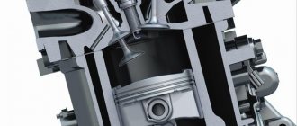
The purpose of the CPG is to convert the energy released during combustion into mechanical action - forward motion. The CPG consists of a liner - a stationary part placed in a block in the cylinder block, and a piston that moves inside this liner.
After the air-fuel mixture is supplied inside the liner, it ignites (from an external source in gasoline engines and due to high pressure in diesel engines). Ignition is accompanied by a strong increase in pressure inside the liner. And since the piston is a moving element, the resulting pressure leads to its movement (in fact, gases push it out of the liner). It turns out that the energy released during combustion is converted into the translational movement of the piston.
For normal combustion of the mixture, certain conditions must be created - the maximum possible tightness of the space in front of the piston, called the combustion chamber (where combustion occurs), an ignition source (in gasoline engines), the supply of a combustible mixture and the removal of combustion products.
The tightness of the space is ensured by the block head, which covers one end of the liner, and by piston rings mounted on the piston. These rings also belong to the CPG parts.
connecting rod
The next component of the crankshaft is the connecting rod. It is designed to connect the CPG piston and the crankshaft and transmit mechanical action between them.
The connecting rod is an I-shaped cross-section rod, which provides the part with high bending resistance. At the ends of the rod there are heads, thanks to which the connecting rod is connected to the piston and crankshaft.
In fact, the connecting rod heads are eyes through which shafts pass, providing a hinged (movable) connection of all parts. At the junction of the connecting rod with the piston, a piston pin (referred to as a CPG) acts as a shaft, which passes through the piston bosses and the connecting rod head. Since the piston pin is removed, the upper head of the connecting rod is one-piece.
At the junction of the connecting rod with the crankshaft, the connecting rod journals of the latter act as a shaft. The lower head has a split design, which allows the connecting rod to be secured to the crankshaft (the removable part is called the cap).
Crankshaft
The purpose of the crankshaft is to provide the second stage of energy conversion. The crankshaft converts the forward motion of the piston into its own rotation. This element of the crank mechanism has a complex geometry.
The crankshaft consists of journals - short cylindrical shafts connected into a single structure. The crankshaft uses two types of journals - main and connecting rod. The first ones are located on the same axis, they are supporting and are designed to movably secure the crankshaft in the cylinder block.
The crankshaft is fixed in the cylinder block with special covers. To reduce friction at the junction of the main journals with the cylinder block and connecting rods with the connecting rod, friction bearings are used.
The connecting rod journals are located at a certain lateral distance from the main ones and the connecting rod is attached to them with the lower head.
The main and connecting rod journals are connected to each other by cheeks. In diesel crankshafts, counterweights are additionally attached to the cheeks, designed to reduce the oscillatory movements of the shaft.
The connecting rod journals together with the cheeks form a so-called U-shaped crank, which converts translational motion into rotation of the crankshaft. Due to the remote location of the connecting rod journals, when the shaft rotates, they move in a circle, and the main journals rotate about their axis.
The number of connecting rod journals corresponds to the number of engine cylinders, while the main ones are always one more, which provides each crank with two support points.
At one end of the crankshaft there is a flange for attaching the flywheel - a massive disk-shaped element. Its main purpose: the accumulation of kinetic energy due to which the reverse operation of the mechanism is carried out - the transformation of rotation into the movement of the piston. At the second end of the shaft there are seats for drive gears of other systems and mechanisms, as well as a hole for fixing the drive pulley of motor attachments.
What is the crankshaft sensor for?
The crankshaft position sensor (CPS) is used in vehicles equipped with electronic engine control systems. Since shaft rotation affects the operation of many functional units and systems, timely supply of fuel to the internal combustion engine cylinders can improve driving characteristics. The crankshaft sensor is responsible for synchronizing work processes. In various car models, its use improves the timing of the ignition or fuel injectors. The device transmits data on the crankshaft position, direction and speed to the electronic control unit.
The following types of sensors are available:
- Magnetic (inductive type) . The signal to the ECU is generated when the synchronization mark passes through the magnetic field that is formed around the sensor. The system does not require separate power and can operate in parallel as a speed sensor.
- Hall sensors (work on the Hall effect) . The current in the device begins to move when a changing magnetic field approaches. The magnetic field overlap is realized by a special synchronizing disk, the teeth of which interact with the magnetic field of the DPKV. An additional function is the ignition distribution sensor.
- Optical . In this case, a toothed disk is also used for synchronization. It blocks the optical flow passing between the receiver and the LED. The receiver detects interruptions in the light flux and transmits a voltage pulse corresponding to the shaft rotation parameters to the electronic control unit.
The crankshaft sensor is installed inside the engine housing, like other control sensors. To install it, a special bracket is used, located near the generator drive pulley. Externally, it differs from sensors for other purposes in the presence of a 55-70 cm long wire with a special connector that connects the device to the electronic control system.
Kneeling crankshaft
When I was studying at a driving school, the teacher at the beginning of the lesson sent some “dunno” to the racks so that he would find and bring the part being studied. Regardless of the name of the part, in order to “help” the unlucky student, everyone pointed to it and of course it was the crankshaft.
That is, the first part that everyone learned to recognize the first time was the crankshaft.
So today we’ll talk about the purpose and design features of the crankshaft, as well as the materials from which it is made.
Why are crankshafts called flat?
In the process of studying the structure of the crankshaft, sometimes it seems that you are in a biology lesson. The first thing that catches your eye is the massive flat “cheeks”, between which there are “necks”. Some journals (as you probably know) are main journals (the shaft rests on them while lying in the crankcase) and connecting rods (it is to them that the connecting rods “cling” from above). If you look at the crankshaft from the front, two options are possible: either the cheeks and journals lie in the same plane, or half of them are located at right angles to the other half. In the first case, the shaft is called flat.
When assembling the engine of your small car, a flat shaft was probably used - this is a natural solution for a 4-cylinder engine. But when creating a V-shaped “eight”, you already have a choice. Initially (at the dawn of the automotive industry), all designers preferred flat shafts, but with increasing power, power units generated more and more vibrations and became increasingly difficult to balance. It was in an attempt to reduce the level of vibration that the creators of the motors came up with a scheme with the necks installed at right angles to each other. And now most V-shaped eights have just such crankshafts. And “flat” ones remained the lot of racing engines or engines for supercars - you can recall Ferrari power units or the 5-liter engine under the hood of the new Shelby Mustang GT350.
The easiest way to understand the difference between a flat-plane crankshaft (right) and a crankshaft with journals mounted at right angles is to use pictures.
Motorists are not going to completely abandon the flat crankshaft. After all, a simpler design makes it more compact and lighter, which means that, other things being equal, such a shaft is able to spin faster, making the engine more responsive. In addition, over the last hundred years, metallurgists have not been lazy - and thanks to advanced materials, which make it possible to make a part noticeably lighter at the same dimensions, modern flat shafts have an order of magnitude less vibration than their distant ancestors.
The question remains: why then are the crankshafts of 4-cylinder engines made flat? The fact is that the level of vibrations caused by the so-called. forces of inertia of the 2nd order (it is they that appear on V-shaped “eights” with a flat crankshaft), strongly depends on the displacement of the engine. 4-cylinder engines are compact - so sometimes you can simply turn a blind eye to such vibrations. And if it’s not possible, it’s easier and cheaper to use the so-called. balance shafts. Which we will talk about another time.
Purpose of the crankshaft
The crankshaft is one of the important engine parts. It converts the translational motion of the piston into rotational motion, which is transmitted through the transmission to the wheels.
Despite the relative complexity of the device, its operating principle is quite simple. In the combustion chamber, fuel is burned and gases are released, which push the pistons and give them forward motion.
The pistons transmit mechanical energy through the connecting rods to the crankshaft journal, as a result, translational motion is converted into rotational motion. As soon as the shaft turns 180˚, the connecting rod begins to move in the opposite direction, returning the piston to its original position - the cycle repeats.
How a crankshaft works - a look from the inside
The operating principle of the crankshaft is as follows. At the moment of maximum removal of the piston, the cheeks and the crankshaft connecting rod are pulled into one line. At this time, fuel begins to burn in the cylinders, and, accordingly, flammable gases are released, which move the piston towards the crankshaft. The connecting rod also moves with it, the lower head of which rotates the crankshaft relative to its axis. As soon as it turns 180°, the crankpin begins to move in the opposite direction, thus moving the piston.
The following picture emerges: the piston evenly moves away and then approaches the part; the extreme points of the piston are called “dead”, since in these positions its speed is zero. Thus, we figured out how the crankshaft works.
The lubrication system in the part also plays an important role . An oil supply is provided from the common line to the main journal supports, which is supplied under pressure. Next, through special channels located in the cheeks, this oil is supplied to the connecting rod journals. Thanks to the oil film, the wear resistance of these elements increases. In addition, oil pressure can be used to check whether the crankshaft journals need replacing. Having decided what the crankshaft is needed for, we can safely say that it occupies one of the leading positions among engine parts.
Home →
Device →
Engine →
Crankshaft (crankshaft) →
This is interesting: Refilling car air conditioners - instructions for a comfortable climate!
The crankshaft is a structure, in short, a piece of iron that is bent many times
The crankshaft consists of main journals located on the same axis, connected by cheeks and connecting rod journals, the number of which is determined by the number of cylinders. Using connecting rods, the crankshaft journals are connected to the pistons.
Depending on how the main journals are located, the crankshaft can be:
- full-support - if the main journals are located on both sides of the connecting rod journal;
- partial support - if the main journals are located only on one side of the connecting rod journal.
Most modern car engines are equipped with full bearing crankshafts.
Basic elements of HF
The main elements include:
- The main journal is the main part of the assembly, which is located on the main bearings (liners) located in the crankcase;
- Crankpin – connects the crankshaft to the connecting rods. The connecting rod mechanisms are lubricated through special oil channels. The connecting rod journals are shifted to the sides;
- Crankshaft cheeks - connect the main and connecting rod journals;
- Counterweights - balance the weight of the pistons and connecting rods;
- The front, frontal part or toe is a mechanism element equipped with a gear (pulley) and gear, and in some cases also a vibration damper. It controls the drive power of the gas distribution mechanism (GRM) and other devices;
- The rear part (shank) - an element of the mechanism connected to the flywheel using an oil deflector ridge and an oil drain thread, performs power take-off.
The back and front sides of the crankshaft are sealed with protective oil seals, which prevent oil leakage in places where the flywheel extends beyond the cylinder block.
The movement of the crankshaft is guaranteed by plain bearings, which are the thinnest steel liners with a special anti-friction layer. To prevent axial displacement, there is a thrust bearing installed on the main journal (extreme or middle).
Materials for production
The crankshaft is a hard worker that is subjected to strong, rapidly changing loads. Its reliability indicators are determined by the design features and materials from which it is made.
This engine element usually has a solid structure. So the materials for its manufacture should be used as durable as possible, because the stable operation of the system depends on this. The best materials are carbon and alloy steel and high-strength cast iron.
Crankshafts are made by casting, forging steel, and then turning them. Blanks are produced by hot stamping or casting.
An important point is the location of the material fibers in the workpiece. To prevent them from being cut during processing, bending strands are used. When the workpiece is made, it is again treated with high temperature and freed from scale.
The material and production technology depend on the class and type of car.
- For production models, crankshafts are produced by cast iron. This reduces the cost.
- For expensive sports models, forged steel crankshafts are used. This option has a number of advantages in terms of size, weight and strength, and is increasingly used in the automotive industry.
- For super-expensive engines, the product is machined from solid steel blanks. At the same time, a decent portion of the material remains in waste.
Design features
Now you know that in addition to serial ones, there are also sports crankshafts. They make it possible to accelerate the piston stroke at the extreme point of compression, thanks to the special shape of the connecting rod journals. On a standard shaft they are round, but on a sports shaft they are slightly elongated, due to this the engine characteristics change.
Many motorists believe that by marking the crankshaft they can learn about its characteristics. This is a misconception - the marking is only a number in the manufacturer’s catalog, which is used to select spare parts. It has nothing to do with the properties of the product.
Congratulations, gentlemen. Now you know that the crankshaft is not only a heavy piece of iron, but also an irreplaceable part on which a comfortable ride and the service life of the engine and its components depend.
It also provides many of the car’s devices with torque: transmission, generator, cardan shafts, and so on to the wheels.
Of course, you don’t have to tell your girlfriend about this, but tell your motorist friends via social networks. Let them read our blog too - there will be a lot of interesting things.
Dimensions
The thickness of the main bearing is about 1.5-2 millimeters. It should be noted that sometimes a different composition may be used as materials for the production of this part - instead of copper and lead-tin alloys, special aluminum-based alloys are used.
But there is no standardization of materials for the manufacture of these products - each manufacturer makes the liner according to its own unique formulas. The only thing that unites the products with each other is the steel strip.
Practice shows that the following layer sizes are used in the production of plain bearings. Thus, the thickness of the steel base is 0.9 millimeters or more. The main layer has a thickness of up to 0.75 millimeters. Nickel layer – 0.001. The layer of tin and lead alloy is 0.02-0.04 millimeters. Tin layer - 0.005.
Any alloys used in production are individually selected for each engine and calculated taking into account the hardness of the materials from which the crankshaft is made. To increase the service life and performance of new or repair motors, it is recommended to use only those parts that the manufacturer recommends.
The thinner the main bearing, the better performance it has. Thinner products lie on the bed much better, have better heat dissipation, and the gaps in them are smaller. In modern motors, manufacturers are trying to use thinner plain bearings.
The liner must be made from more than just the right components. The shape is also very important. The fact is that for proper installation it is necessary that the bearing have an interference fit on the diameter of the crankshaft bed.
The tension is made not only along the diameter of the product, but also along its length. This makes it possible to achieve excellent contact between the bearing liner and the bed. For shafts with a diameter of up to 40 millimeters, the interference should be from 0.03 to 0.05 millimeters. For larger shafts (70 millimeters) and above, the interference ranges from 0.06 to 0.08 millimeters.
This part also has an upper part - these are the main bearing caps. They are fixed with bolts or studs on the engine crankcase.
This part, namely the liner, is produced by stamping from a steel strip. The stamp gives the part its shape. And then the end parts and working surface are processed. This detail is very accurate. Tolerance from the nominal size to 0.02 millimeters in length and up to 0.005 in thickness.