Adjustment of valves
If knocking, unstable operation, or increased vibration occur, you should pay attention to the valves.
If the valve timing of the gas distribution mechanism is disrupted, they do not operate accurately, that is, the full volume of gas does not enter the working area of the cylinders, complete combustion of the fuel-air mixture in the working chamber does not occur, and the cylinders are not purged. This is all accompanied by the appearance of a shock load on the camshaft cams on the drive lever and the shaft rod. Fuel and engine oil consumption also increases. What happens if you drive with unadjusted valves? Answer: rapid wear of engine parts, increasing cost and repair time.
Rubber oil deflectors, also known as oil deflectors, also burn out due to a burnt valve cap, which leads to increased engine oil consumption. If the wear of engine parts is large, then it may be better and easier to do an engine swap with your own hands or at a service station.
Even if your engine does not have a belt drive, but a chain drive, then if you do not change the chain before its service life expires, the valves will bend on the piston, as, for example, in the sr20det engine manufactured by Nissan.
The procedure for adjusting valves VAZ 2101-2107
First we prepare the car:
- wait until the engine cools down if it was running;
- park the car on level ground;
Valve adjustment procedure:
- Remove the air filter cover and the filter itself.
- Remove the air damper control cable (choke).
- Remove the throttle linkage.
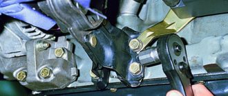
- Unscrew the nuts securing the valve cover and remove it.
- Before adjusting the valves, immediately check how the chain is tensioned. If the tension is not normal, you will have to do the work again.
- Remove the distributor cover.
- We install the piston in the 4th cylinder at top dead center (TDC). TDCs are set using marks on the internal combustion engine crankshaft pulley and the camshaft drive cover, and marks are also applied to the camshaft gears and camshaft cover. The mark is set with a special key for the internal combustion engine crankshaft pulley bolt. If you don’t have a key, you can set the 4th piston to TDC by rotating one of the rear wheels. Raise one side with a jack and place the gear shift lever in 4th gear to make it easier to turn and turn the wheel slowly. When setting marks without a key, you will need an assistant to look at the marks.
- When the marks on the camshaft and the camshaft cover are aligned, check that the marks on the crankshaft are also aligned. You can also check whether the marks on the distributor slider match. The contact terminal should be directed to the high voltage wire terminal of the fourth cylinder. We have already discussed how to determine whether ignition is early or late in another article.
- After the marks match, we proceed to adjusting the valve clearances.
The correct procedure for adjusting the valve mechanism of the VAZ “Classic” 2101-2107. Crank angle Adjustable valves 8 and 6 180 4 and 7 360 1 and 3 540 5 and 2
Disconnect the filter mounting tubes and remove the mount.
From the table we see that if the 4th piston is set to top dead center, then we measure and adjust the 6th and 8th valves.
If everything you need is available, you can start
- Before starting work, let the engine cool down; its temperature should not be higher than 20°.
- Remove the air cleaner cover and take out the air filter.
- Unscrew the 4 nuts with a key “8”, then you need to remove the hoses going to it (large from below, small from the carburetor side)
- Remove the air cleaner housing.
- Disconnect the choke cable; a screwdriver and a key set to “8” will help you with this.
- Turn off the throttle, remove the spring and washer.
- Using a “10” socket wrench, unscrew the 8 nuts that secure the valve cover.
- Now you can remove the cover.
- Take a prepared 0.15 probe or a special device, if you have one, and open-end wrenches for “17” and “13”.
- Turn the engine until the marks on the crankshaft (front engine cover and pulley), as well as on the camshaft sprocket, coincide.
- In this position, you need to check the gap in cams 6 and 8 (refer to the table below)
- Count the cams from the camshaft sprocket.
- Install the dipstick above the rocker under the camshaft, when viewed from the right side - the location of the dipstick installation is clearly visible. If the dipstick is installed freely, loosen the nut at “17” at the corresponding rocker, holding the nut at “13” from turning with the other hand.
- Next, turn the nut at “13” a little and lock it with the nut at “17”, then check the gap again using a feeler gauge. Your task is to achieve a tight movement of the probe with slight nudging.
- If you managed to achieve the required gap, make the final tightening with the key set to “17”. After this, you can begin adjusting the next cam.
- Rotate the motor shaft clockwise 180°, with the mark on the sprocket pointing to “9 o’clock” when viewed from the camshaft). Here, great accuracy is not particularly important, so everything is approximate.
- The next two cams 4 and 7 must be adjusted according to the table above.
- Next, rotate the motor shaft 180°, the mark on the sprocket is at the bottom (at “6 o’clock”), and on the pulley. must match.
- Adjust cams 1 and 3 according to the table.
- And finally, another 180° turn at the 3 o’clock star. Cams 2 and 5. As a rule, after removing and installing the camshaft, there is a need to turn the starter, then check the clearances again and, if necessary, make adjustments.
- Before closing the cover, make sure that all the nuts on “17” are well tightened; if the gasket is damaged or you damaged it during removal, replace it.
The cover nuts are tightened from the center to the edges (the same as when replacing the camshaft or cylinder head) and the main thing is not to pull too hard. Fortunately, the valve cover is not capricious and, in principle, no tightening rules need to be followed.
Reassemble everything in reverse order and perform a test run. That's all for me, now you know how to adjust the valves on a VAZ 2101, I hope everything works out for you. As you can see, adjusting the valves can be done at home without much difficulty and for this it is not at all necessary to go to a service station and pay a lot of money, you just need to have free time and “direct hands”.
Purpose and design of the valve mechanism of the VAZ 2101
The operation of an internal combustion engine is impossible without a gas distribution mechanism (GDM), which ensures timely filling of the cylinders with the fuel-air mixture and removes its combustion products. To do this, each cylinder has two valves, the first of which is intended for the intake of the mixture, and the second for the release of exhaust gases. The valves are controlled by camshaft cams.
The camshaft is driven by the crankshaft via a chain or belt drive. Thus, the piston system ensures time-distributed intake and exhaust of gases in compliance with the sequence of valve timing. The rounded tips of the camshaft cams press on the rocker arms (levers, rockers), which, in turn, actuate the valve mechanism. Each valve is controlled by its own cam, opening and closing it in strict accordance with the valve timing. The valves are closed using springs.
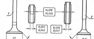
The valve consists of a rod (rod, neck) and a cap with a flat surface (plate, head) covering the combustion chamber. The rod moves along a sleeve that guides its movement. The entire timing belt is lubricated with engine oil. To prevent lubricant from entering the combustion chambers, oil seals are provided.
Each valve timing must strictly correspond to the position of the pistons in the cylinders. Therefore, the crankshaft and camshaft are rigidly connected through the drive, with the first shaft rotating exactly twice as fast as the second. The full operating cycle of the engine consists of four phases (cycles):
- Inlet. Moving down in the cylinder, the piston creates a vacuum above itself. At the same time, the intake valve opens and the fuel-air mixture (FA) enters the combustion chamber under low pressure. When the piston reaches bottom dead center (BDC), the intake valve begins to close. During this stroke, the crankshaft rotates 180°.
- Compression. Having reached BDC, the piston changes direction of movement. As it rises, it compresses the fuel assembly and creates high pressure in the cylinder (8.5–11 atm in gasoline engines and 15–16 atm in diesel engines). In this case, the inlet and outlet valves are closed. As a result, the piston reaches top dead center (TDC). In two strokes, the crankshaft made one revolution, that is, it rotated 360°.
- Working progress. A spark ignites the fuel assembly, and under the pressure of the resulting gas, the piston is directed to BDC. During this phase the valves are also closed. Since the beginning of the working cycle, the crankshaft has rotated 540°.
- Release. Having passed BDC, the piston begins to move upward, compressing the gaseous combustion products of the fuel assembly. At the same time, the exhaust valve opens, and under the pressure of the piston, gases are removed from the combustion chamber. In four strokes, the crankshaft made two revolutions (rotated 720°).
The gear ratio between the crankshaft and camshaft is 2:1. Therefore, during the operating cycle the camshaft makes one full revolution.
The timing belts of modern engines differ in the following parameters:
- upper or lower location of the camshaft;
- number of camshafts - one (SOHC) or two (DOHC) shafts;
- number of valves in one cylinder (from 2 to 5);
- type of drive from the crankshaft to the camshaft (toothed belt, chain or gear).
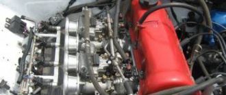
The first carburetor engine of VAZ models produced from 1970 to 1980 has four cylinders with a total volume of 1.2 liters and a power of 60 hp. With. and is a classic in-line four-stroke power unit. Its valve train consists of eight valves (two for each cylinder). Unpretentiousness and reliability in operation allows it to use AI-76 gasoline.
Video: operation of the gas distribution mechanism
Gas distribution mechanism VAZ 2101
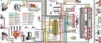
The gas distribution mechanism of the VAZ 2101 is driven by the crankshaft, and the camshaft is responsible for the operation of the valves.
The torque from the engine crankshaft (1) through the drive sprocket (2), chain (3) and driven sprocket (6) is transmitted to the camshaft (7), located in the cylinder head (cylinder head). The camshaft lobes periodically act on the drive arms or rockers (8), driving the valves (9). Thermal clearances of the valves are set by adjusting bolts (11) located in the bushings (10). Reliable operation of the chain drive is ensured by the bushing (4) and the adjusting unit (5), the tensioner, and the damper (12).
The power strokes in the cylinders of the VAZ 2101 engine have a certain sequence.
Main malfunctions of the VAZ 2101 timing belt
According to statistics, every fifth engine malfunction occurs in the gas distribution mechanism. Sometimes different faults have similar symptoms, so a lot of time is spent on diagnosis and repair. The following are the most common causes of timing belt failure.
- Incorrectly set thermal gap between rockers (levers, rocker arms) and camshaft cams. This results in incomplete opening or closing of the valves. During operation, the valve mechanism heats up, the metal expands, and the valve stems elongate. If the thermal gap is set incorrectly, the engine will have difficulty starting and will begin to lose power, popping noises will appear from the muffler and a knocking noise will appear in the engine area. This malfunction is eliminated by adjusting the gap or replacing the valves and camshaft if they are worn.
- Worn valve stem seals, valve stems or guide bushings. The consequence of this will be an increase in engine oil consumption and the appearance of smoke from the exhaust pipe during idling or acceleration. The malfunction is eliminated by replacing the caps, valves and repairing the cylinder head.
- Failure of the camshaft drive as a result of a weakened or broken chain, breakdown of the tensioner or chain guide, wear of the sprockets. As a result, the valve timing will be disrupted, the valves will freeze, and the engine will stall. It will require a major overhaul with the replacement of all failed parts.
After eliminating any of the malfunctions of the VAZ 2101 engine, it will be necessary to adjust the gap between the rockers and the camshaft cams.
Video: the influence of thermal valve clearance on timing belt operation
Why are guide bushings needed?
At the beginning and middle of the last century, car cylinder heads were made of cast iron, and the valves were simply inserted into precisely drilled holes. But subsequently, manufacturers abandoned cast iron heads due to their heavy weight and insufficient removal of excess heat, and they were replaced by lightweight cylinder heads made of aluminum alloys. These metals have excellent thermal conductivity, but have little resistance to wear from friction.
To solve the problem, a guide sleeve was invented - an intermediary between the soft alloy of the cylinder head and the steel valve stem, which constantly moves up and down during operation. Made of cast iron or special bronze, it is securely pressed into the cylinder head body, and the valve is inserted inside with minimal clearance.
The engine diagram shows the location of the guide bushings
The bushing itself is a hollow cylinder, made exactly to size for a specific car model. The outer surface is polished and smooth to the touch, and the inner surface has a spiral-shaped groove in the form of a thread. Motor oil moves along it, lubricating the valve axis and reducing friction. A shallow recess is made in the upper part of the guide part, into which a retaining ring is inserted.
On the left is the bushing for the exhaust valve, on the right is for the intake valve
Bronze bushings for VAZ 2109 all look the same
Bushings perform the following functions:
- as the name implies, they direct the movement of the valve so that its plate is clearly aligned with the seat and fits tightly to it;
- take on the load from the friction force that occurs during the translational and reciprocal movement of the valve stem;
- the valve cup gets very hot in the combustion chamber, and the bushing transfers this heat to the aluminum alloy of the cylinder head;
- Thanks to a special groove, the part provides lubrication of rubbing surfaces.
Cast iron parts of VAZ 2106 - intake bushings are shorter than exhaust bushings
When the element is pressed into the cylinder head hole, its upper part of smaller diameter protrudes several millimeters above the surface. This is necessary to install an oil seal on it (also known as a valve seal), which prevents lubricant from the upper part of the engine from entering the combustion chamber through the inner hole of the bushing.
This is what the protruding part looks like where the oil seal is put on
Dismantling and repair of the cylinder head of the VAZ 2101
To replace valve mechanisms and guide bushings, you will need to dismantle the cylinder head. This operation is quite labor-intensive and painstaking, requiring certain metalworking skills. To perform this you will need the following tools:
- a set of wrenches (heads 8, 10, 13, 17, 19 are required);
- slotted and Phillips screwdrivers;
- pliers;
- mandrels for pressing out and pressing in guide bushings;
- device A.60311/R for removing valve springs (depressurizer);
- puller and mandrel for oil seals;
- torque wrench.
Before dismantling the cylinder head, you must:
- Drain antifreeze from the engine cooling system.
- Remove the air filter and carburetor, first disconnecting all pipes and hoses.
- Disconnect the wires, unscrew the spark plugs and antifreeze temperature sensor.
- After unscrewing the fastening nuts with a size 10 wrench, remove the valve cover along with the old gasket.
Replacing valve springs and oil seals
Support bearings, camshaft, springs and oil seals can be replaced without removing the cylinder head. To do this, you will need a device for extracting (loosening) the valve springs. First, the specified elements are replaced on the valves of the first and fourth cylinders, which are at TDC. Then the crankshaft is turned by a crooked starter 180°, and the operation is repeated for the valves of the second and third cylinders. All actions are performed in a strictly defined sequence.
- A soft metal rod with a diameter of about 8 mm is inserted into the spark plug hole between the piston and the valve. You can use tin solder, copper, bronze, brass, or, in extreme cases, a Phillips screwdriver.
If no other repair work is required, the timing belt is assembled in the reverse order. After this, it is necessary to adjust the thermal clearance of the valves.
Replacement and grinding of valves, installation of new guide bushings
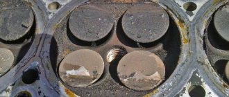
If the valve caps are burnt out, or a coating of impurities in oil and fuel has formed on them, preventing a tight fit to the seats, the valves must be replaced. This will require dismantling the cylinder head, that is, you will need to complete all the points of the above algorithm before installing new oil seals on the valve necks. The caps and springs themselves can be installed on the removed cylinder head after replacing and grinding in the valves. The work is performed in the following order.
- The hoses are disconnected from the carburetor, the inlet pipe and the outlet pipe of the cylinder head cooling jacket.
- The starter protective shield and the exhaust pipe of the mufflers are disconnected from the exhaust manifold.
- The oil pressure sensor is disconnected.
- The bolts securing the cylinder head to the cylinder block are broken off and then unscrewed with a wrench and ratchet. The cylinder head is removed.
- If the valve mechanisms have not been disassembled, they are removed in accordance with the instructions given above (see “Replacing valve springs and valve stem seals”).
Video: repair of cylinder head VAZ 2101–07
Preparatory work
So, the engine is cooled down, and the car itself is placed on a flat surface and immobilized. You can start working:
- Remove the carburetor air filter cover and remove the filter;
- We unscrew the filter mounting bolts and remove it, having first disconnected the pipes going to it;
- We remove the cable for manual control of the air damper (choke) and disconnect the throttle linkage;
- Unscrew the bolts securing the valve cover and dismantle it;
- Check the chain tension (it must be normal, otherwise you will have to adjust the tension first);
- Remove the distributor cap.
Now you need to set the TDC of the piston in the 4th cylinder and the marks on the knees will help with this. camshaft drive shaft and cover. shaft, as well as on the camshaft gear and its cover.
To do this, you can use a key of appropriate size, which you need to rotate the knees. shaft for the drive pulley bolt. Or use one of the drive wheels. To do this, you need to hang it with a jack, engage 4th gear and slowly turn the raised wheel. In this case, the transmission will ensure rotation of the crankshaft. But with the second method, you will need an assistant, since it will be difficult to check the coincidence of the marks.
Adjusting the thermal clearance of valves
A design feature of engines of classic VAZ models is that during operation the gap between the camshaft cam and the rocker-valve pusher changes. It is recommended to adjust this gap every 15 thousand km. To work, you will need wrenches 10, 13 and 17 and a feeler gauge 0.15 mm thick. The operation is simple, and even an inexperienced car enthusiast can perform it. All actions are performed on a cold engine in the following order:
- According to the above instructions, remove the valve cover (Section 4 of the section “Dismantling and repairing the VAZ 2101 cylinder head”), then the ignition distributor cover. The oil dipstick is removed.
- The crankshaft and camshaft marks are aligned (clause 5 of the section “Dismantling and repair of the VAZ 2101 cylinder head”). The piston of the fourth cylinder is set to the TDC position, with both valves closed.
- A feeler gauge is inserted between the rocker and the camshaft cam of valves 8 and 6, which should fit into the slot with little difficulty and not move freely. Use a 17 wrench to loosen the lock nut, and use a 13 wrench to set the gap. After this, the adjusting bolt is tightened with a locknut.
Video: adjusting valve clearance on VAZ 2101
Stages of work, tools
All adjustment work is carried out in several stages:
- Preparatory work, partial disassembly of the motor to provide access to the valve mechanism;
- Adjustment;
- Assembly.
Adjusting the valve clearances of the VAZ-2106 is carried out with the following tools:
- A set of socket and open-end wrenches (open-end wrenches for 13 and 17 are required);
- Gap gauge;
- Screwdrivers;
- Rags;
- Marker.
Regarding the dipstick. Checking and adjustment is carried out with a feeler gauge with a thickness of 0.15 mm. In this case, a regular measuring element will not work; a special one with an increased width is required.
Note that all Zhiguli “Classic” models are carburetor, except for one of the 2107 modifications, so let’s look at what preparatory work needs to be done before adjusting the VAZ-2104 valves (carburetor).
Valve lid
The valve cover covers and seals the timing belt, preventing grease from camshaft, valves and other parts from leaking out. In addition, new engine oil is poured through its neck when replacing. Therefore, a sealing gasket is installed between the valve cover and the cylinder head, which is changed every time after repair or adjustment of the valves.
Before replacing it, you should thoroughly wipe the surfaces of the cylinder head and cover to remove any remaining engine oil. Then the gasket is put on the cylinder head studs and pressed with the lid. It is necessary that the gasket fits exactly into the grooves of the cover. After this, the fastening nuts are tightened in a strictly defined sequence.