Work progress
- First you will need to clean the piston head of carbon deposits. The piston must be replaced if there are burrs, burn marks, deep scratches, or cracks on it. Then clean the grooves for the piston rings. It is convenient to perform this operation using a piece of an old ring.
- You should also clean the oil drain holes. Use a suitable piece of wire.
- Check the clearances between the rings and grooves on the piston. Nominal clearance, mm: upper compression ring 1 – 0.04–0.075; lower compression ring 2 – 0.03–0.065; oil scraper ring 3 – 0.02–0.055; The maximum permissible gap for all rings is 0.15 mm.
- The most accurate way to determine clearances is by measuring the rings and grooves on the piston. To do this, measure the thickness of the rings with a micrometer in several places around the circumference, then...
- ...using a set of feeler gauges, measure the width of the grooves in several places around the circumference. Calculate the average clearance values (the difference between the ring thickness and the groove width). If at least one of the gaps exceeds the maximum permissible, replace the piston with rings.
- Measure the gaps in the ring locks by inserting the ring into a special mandrel. If there is no mandrel, insert the ring into the cylinder (in which it worked), use the piston as a mandrel to push the ring into the cylinder so that it is installed evenly in the cylinder, without distortions and...
- ...measure the gap in the ring lock with a feeler gauge. The nominal gap should be 0.25–0.45 mm, the maximum permissible (as a result of wear) is 1.0 mm. If the gap exceeds the maximum permissible, replace the ring.
- If the gap is less than 0.25 mm, carefully file off the ends of the ring with a file.
- Check the clearances between the pistons and cylinders. The clearance is defined as the difference between the measured diameters of the piston and cylinder. The nominal gap is 0.025–0.045 mm, the maximum permissible is 0.15 mm. If the gap does not exceed 0.15 mm, you can select pistons from subsequent classes so that the gap is as close as possible to the nominal one. If the gap exceeds 0.15 mm, bore the cylinders to the next repair size and install pistons of the corresponding repair size. Measure the diameter of the piston at a distance of 55 mm from its bottom in a plane perpendicular to the piston pin.
- Then measure the diameters of the cylinder in two perpendicular planes (along B and across A of the cylinder block) and in four zones (1, 2, 3 and 4). For this you need a special device - a bore gauge.
- When replacing parts of the connecting rod and piston group, it is necessary to select pistons to cylinders by class and one group by weight, as well as piston pins to pistons by class and connecting rods by weight. To select pistons for cylinders, calculate the gap between them. For the convenience of selecting pistons for cylinders, cylinders and pistons, depending on their diameters, are divided into five classes: A, B, C, D, E. Spare parts are supplied with pistons of nominal sizes of three classes A, C, E and two repair sizes. The first repair is increased by 0.4 mm, the second - by 0.8 mm. Based on weight, the pistons are divided into three groups: normal, increased by 5 g and decreased by 5 g. Pistons of the same group must be installed on the engine. For repair size pistons, spare parts include repair size rings increased by 0.4 mm and 0.8 mm. The number “40” is stamped on the rings of the first repair size, and “80” on the second.
- On the cylinder block, a group of cylinders is knocked out on the lower plane of the block (the mating plane under the oil sump) opposite each cylinder.
- The following data is stamped on the bottom of the piston: 1 – piston class based on the pin hole; 2 – piston diameter class; 3 – arrow showing the direction of installation of the piston; 4 – repair size (1st repair – triangle, 2nd repair – square); 5 – weight group (normal – “G”, increased by 5 g – “+”, reduced by 5 g – “-”).
- Replace pins with cracks. The finger should easily enter the piston using the force of the thumb. Insert your finger into the piston. If play is felt when rocking the finger, replace the piston. When replacing a piston, select a pin according to its class. The piston pins are divided by diameter into three classes (1st, 2nd, 3rd) every 0.004 mm. The class of the finger is marked on its end with paint. The piston pin class is stamped on the piston bottom, the connecting rod pin class is stamped on the connecting rod cap.
- Replace broken rings and oil ring expander.
- Replace broken or cracked circlips that hold the piston pin in place. The ends of the retaining rings must be in the same plane. Replace bent rings.
- Replace bent connecting rods. Replace the connecting rod if there are burrs and deep scratches in the bushing 1 of the upper head. Replace the connecting rod if, upon disassembling the engine, it is discovered that the connecting rod bearings have rotated in the connecting rod. The connecting rods are processed together with the covers, so they need to be replaced as a set.
- Insert a pin into the upper end of the connecting rod. If play is felt when rocking the pin, replace the connecting rod. Connecting rods assembled with covers are divided into classes based on the weight of the upper and lower heads.
- The engine must have connecting rods of the same class. The connecting rod is marked on its cover: 1 – connecting rod class by weight (letter or paint), 2 – connecting rod class by pin.
- If there are deep scratches, scratches, nicks on the surfaces on which the oil seals operate, the crankshaft must be replaced.
- Measure the main and connecting rod journals of the crankshaft. Nominal diameters of the crankshaft journals, mm: main – 50.799–50.819; connecting rods - 47.830–47.850. If the wear of the journals exceeds 0.03 mm or the ovality of the journals exceeds 0.03 mm, they need to be ground to the nearest repair size. There are four repair sizes with a reduction in the diameter of the journals: the first - 0.25 mm; second – 0.5 mm; third – 0.75 mm; fourth – 1.00 mm.
- If there are minor scuffs, marks, or scratches on the main and connecting rod journals 1, you need to grind them to the nearest repair size. It is recommended to carry out this work in a specialized workshop. Then polish the journals and blunt the sharp edges of the chamfers of the oil channels 2 with an abrasive cone. Wash the crankshaft and blow out the oil passages with compressed air. The ovality and taper of all journals after grinding should not exceed 0.005 mm. After grinding the journals, install inserts of repair sizes.
- If there are burrs, marks or peeling on the working surfaces of the thrust half-rings, replace the half-rings. It is prohibited to carry out any adjustment work on the half rings.
- Measure the axial clearance of the crankshaft. To do this, install the crankshaft and thrust half-rings into the cylinder block and tighten the bolts securing the main bearing caps.
- Install the indicator so that its leg rests against the shaft flange. Move the crankshaft as far as it will go from the indicator and set the indicator arrow to 0. Move the shaft in the opposite direction. The indicator will show the gap size. The nominal axial clearance of the crankshaft is 0.06–0.26 mm, the maximum permissible is 0.35 mm. If the gap exceeds the maximum permissible, replace the thrust half-rings. Spare parts are supplied with thrust half-rings of two sizes: nominal – 2.31–2.36 mm and repair (increased by 0.127 mm) – 2.437–2.487 mm.
- Inspect the connecting rod and main bearings. If they have cracks, burrs, or chipping, replace the liners. It is prohibited to carry out any adjustment work on the liners. Nominal thickness of liners, mm: main ones – 1.824–1.831; connecting rods - 1.723–1.730. The inserts are supplied in spare parts in four repair sizes, with increased thickness: the first – by 0.25 mm; the second – by 0.5 mm; third – by 0.75 mm; the fourth - by 1.00 mm.
- Check the clearances between the main bearing shells and the crankshaft journals. It is recommended to carry out this work in a specialized workshop. Measure the diameter of the journals and the diameters of the main bearings by installing the caps with liners on the block and tightening them to the appropriate torques. Calculate the gap. The gaps between the liners and the crankshaft journals are equal: main bearings (nominal) - 0.026–0.073 mm, maximum permissible - 0.15 mm; connecting rod bearings (nominal) – 0.02–0.07 mm, maximum permissible – 0.1 mm. If the gap exceeds the maximum permissible, the crankshaft must be ground to the next repair size.
- In a specialized workshop you can measure the runout of the crankshaft journals. The runout should be: main journals and seating surface under the drive gear of the oil pump - no more than 0.03 mm; landing surface for the flywheel – no more than 0.04 mm; seating surface for pulleys and oil seals – no more than 0.05 mm.
- Thoroughly clean and flush the crankshaft oil passages.
- It is not recommended to press out the plugs yourself; to do this, contact a specialized workshop.
- Thoroughly clean the surfaces of the cylinder block from any remaining old gaskets. Inspect the block carefully. If cracks are found, the block must be replaced as an assembly with the main bearing caps.
- Check the tightness of the cylinder block cooling jacket. To do this, plug the hole under the water pump (installing the pump with a gasket) and pour Antifreeze-A40 into the cooling jacket. If there is a noticeable leak in any place, then the unit is leaking and needs to be replaced.
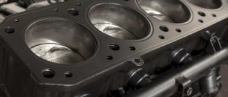
- Inspect the cylinders. If there are scratches, burrs, holes, etc. on the cylinder mirror, bore the cylinders to the repair size (it is recommended to have this work done in a specialized workshop) or replace the cylinder block. For various defects with a depth of more than 0.8 mm, the block cannot be repaired and must be replaced.
- Clean the carbon deposits on the top of the cylinders. If a belt has formed there due to wear on the cylinders, remove it with a scraper. Check the wear of the cylinders by measuring their diameters (see point 10).
Disassembling the 2110 engine
The procedure for assembling the VAZ 2111 engine
Installing the clutch disc and basket
We install the clutch disc and basket on the flywheel. The clutch disc must be centered in relation to the internal bearing of the shaft cranks using a special shaft. On which there are two surfaces, one corresponds to the inner diameter of the bearing, the other corresponds to the inner diameter of the splined part of the clutch disc. The clutch disc is located with its protruding part towards the basket. After centering, install and tighten the clutch basket.
Crankshaft repair
Grinding of the crankshaft is performed on a rotating emery wheel. During operation, the shaft is rotated around the base axes of either the main or connecting rod journals. It is also necessary to ensure that the center-to-center condition is maintained and to be extremely careful about maintaining the shape of the fillets, otherwise repairs can only accelerate the destruction of the crankshaft.
After grinding, the shaft and flywheel assembly must be dynamically balanced to avoid vibration in the rebuilt engine. However, in practice this condition is rarely met, especially during individual repairs.
In some cases, it is impossible to repair damage to the journals by grinding. Then you can consider the option of surfacing or spraying (including plasma) followed by grinding to zero (nominal) size. Depending on the material being deposited, the strength of the journal may even increase compared to factory values. At the final stage of processing, the journals are polished and finished to achieve the optimal degree of roughness.
It is important to take into account that the sizes of necks of the same type must necessarily match. Different types may have different diameters
For example, the main ones can be of the second repair size, and the connecting rods can be of the third. The exception is situations of field repair, in which the journals may not have a standard repair size at all.
It should also be noted that the specific loads placed on the crankshaft often cause its failure. Most often this happens due to an increase in gaps with the liner, which entails deterioration of lubrication. A broken crankshaft cannot be repaired and must be replaced.
What's the result?
Taking into account the above information, we can conclude that the appearance of knocking in the engine is a sign for immediate cessation of operation of the vehicle. It should also be taken into account that the condition of the liners is greatly influenced by the operating temperature of the power unit. In other words, engine overheating can lead to cranking of the connecting rod or main bearings, engine jamming, etc. In this case, the engine may become completely unusable, as the crankshaft bed breaks, the crankshaft itself, the cylinder block, etc. fail.
As for engine oil, it is necessary to use only those fuels and lubricants that meet all the requirements and necessary approvals of the power unit manufacturer. Also, the oil and oil filter must be changed promptly to prevent dirt and mechanical particles from getting into the lubricant. The lubrication system itself also deserves increased attention, since decreased performance or malfunctions can lead to oil starvation, which significantly increases the risk of bearings turning.
Finally, we add that the gasoline engine needs to be warmed up after a cold start, then you need to drive without loads until the power plant reaches operating temperatures. In the case of a diesel engine, the engine warms up while driving; it is not recommended to sharply load the unit until it is completely warmed up. It should also be remembered that both a new engine and a motor after repair need to be run in, since loaded pairs and mating elements need to be ground in.
Is it possible to tune the Priora 126 engine?
Even with a strong desire, the 126 engine will not be able to reach a speed of 100 km/h in a few seconds. Without tuning the Lada Priora engine, overtaking prestigious brands will also not be possible.
According to many motorists, it is necessary to install a turbocharger from the very beginning. In this case, the engine power will increase by no more than 15 - 20%. Special filter elements are additionally installed here to clean the cold air as it enters the engine.
The main improvements to the 21126 motor are:
- cylinder boring;
- increase in piston stroke.
With the help of these modifications, it is possible to most effectively boost the 126 engine, the power of which increases by 50 horsepower. The main purpose of boring is to increase the volume of the cylinders. The process comes down to primitive actions:
- cylinder walls are reduced in thickness;
- more gasoline is burned in the resulting volume;
- engine performance increases;
- power increases.
When choosing a future car, we definitely pay attention to what kind of power unit (heart) it has. Not only the dynamics depend on the motor, but also how much money is required for its maintenance
Do you know which modern VAZ engine to choose?
Toyota pistons markings
The pistons on Toyota engines also have their own designations and sizes. For example, on the popular Land Cruiser, the pistons are designated by the English letters A, B and C, as well as numbers from 1 to 3. Accordingly, the letters indicate the size of the hole for the piston pin, and the numbers indicate the size of the piston diameter in the “skirt” area. The repair piston has +0.5 mm compared to the standard diameter. That is, only the letter designations change for repair shops.
Please note that when purchasing a used piston, it is necessary to measure the thermal gap between the piston skirt and the cylinder wall. It should be within 0.04...0.06 mm
Otherwise, it is necessary to carry out additional diagnostics of the engine and, if necessary, carry out repairs.
Tightening torque for cylinder head VAZ 2112 16 valves
On the side of the front cover, install the timing belt drive toothed pulley. Then we install the cylinder head.
First install the cylinder head gasket. We check that all the holes in the gasket match the holes in the engine block. We tighten the cylinder head with coupling bolts in four stages.
Calculation of VAZ engine volume, selection of crankshaft
Engine Connecting Rod - Conrod
| Connecting rod length | Neck diameter | Piston pin | Finger fit type | Name |
| 121 | 47,8 | 22 | pressing * | 2108 "standard" |
| 121 | 47,8 | 22 | floating | 2110-12 "standard" |
| 126,4 | 47,8 | 22 | floating | 2110 tuning |
| 129 | 41,5 | 19 | floating | 21128 “standard” - original inserts 21128 |
| 129 |
47.8 22 press-fit 2101 tuning 129.2 47.8 22 floating 2110 tuning
129.2 47.8 20 floating 2110 tuning
131 47.8 19 floating 2110 tuning
133 47.8 19 floating 2110 tuning (STI 217.02)
133 47.8 19 floating 2110 tuning (STI 216.55, H-shaped)
135.1 47.8 19 floating 2110 tuning (STI 216.50, H-shaped)
136 47.8 22 press-fit 2101 “standard”, until 1982 they were produced with an oil nozzle
136 47.8 22 floating 21213 “standard”
Crankshafts – Crankshafts – Cranks
| Piston stroke | crank radius | Crankshaft name |
| 66 | 33 | 66 * 2101 "standard" |
| 80 | 40 | 80 * 2103 "standard" |
| 80 | 40 | 80 * 21213 “standard” - full counterweight |
| 84 | 42 | 86*tuning |
| 86 | 43 | 86*tuning |
| 88 | 44 | 88*tuning |
| 90 | 45 | 90 * tuning (crankpin 43mm) |
| 60,6 | 30,3 | 60.6 * 2108 "standard" |
| 71 | 35,5 | * 21083-12 f"standard" |
| 74,8 | 37,4 | * tuning |
| 74,8 | 37,4 | 74.8 * tuning (STI 116.50, full counterweight) |
| 75,6 | 37,8 | 11183 "standard" |
| 78 | 39 | 78 * tuning |
| 79 | 39,5 | 79*tuning |
| 80 | 40 | 80*tuning |
| 80 | 40 | 80 * tuning (STI 218.00) |
| 83 | 41,5 | 83 * tuning (STI, on order) |
| 84 | 42 | 84 * tuning (STI, on order) |
| 84 | 42 | 84 * 21128 factory stock (STI 218.00, for connecting rods 21128 and bearings 21128) |
| 86 | 43 | 86*tuning |
| 88 | 44 | 88 * tuning (crankpin 45mm) |
Cylinder Blocks
Block height is the distance between the geometric center of the crankshaft and the top plane of the cylinder block.
| Height mm. | cylinder diameter | Name |
| 207,1 | 76 | Block 2101 cylinder diameter 76mm |
| 207,1 | 79 | Block 21011 cylinder diameter 79mm |
| 215,9 | 76 | Block 2103 cylinder diameter 76mm |
| 215,9 | 79 | Block 2106 cylinder diameter 79mm |
| 214,58 | 82 | Cylinder block 21213 |
| 194,8 | 76 | Block 2108 cylinder diameter 76mm |
| 194,8 | 82 | Block 21083 cylinder diameter 82mm |
| 194,8 | 82 | Block 2112 cylinder diameter 82mm |
| 197,1 | 82 | Block 21124 cylinder diameter 82mm |
| 197,1 | 82 | Cylinder block 2108-2112 Kalina (+2.3mm) |
| 198,3 | 82 | Cylinder block 2108-2112 (+3.5mm) |
| 199,3 | 82 | Cylinder block 2108-2112 (+4.5mm) |
| 199,5 | 82 | Cylinder block 2108-2112 (+4.7mm) |
Classic configuration options
| Engine | 2103 | 2106 | 21213 | 1900cc | 2000cc | 2000cc | 1800cc |
| Piston stroke: | 80 | 80 | 80 | 84 | 88 | 90 | 84 |
76 79 82 84 84 84 82.4 Volume cm3. 1450 1567 1690 1861 1950 1994 1790
VAZ piston shortfall 1.6 mm - the distance between the piston at the top dead center and the plane of the cylinder block.
The volume of the VAZ classic combustion chamber is 33.2 mm2.
| initial data |
| piston stroke: | mm |
| cylinder diameter: | mm |
| Porsche chamber volume: | cc |
| piston shortfall: | mm |
| chamber volume in cylinder head: | cc |
| cylinder head gasket: | cc |
result
engine capacity: 1583.66 cc
compression ratio: 9.38:1
AUTO-KOR.RU
daewoo chevrolet hyundai
, -2108 . 150. 0,1 ( ) . , 30 160. 200 .
1. . . , : 025 — , , 0,25 . , : 050, 075, 100. . ( ) . , . , . .
2. . (2,310-2,360 ) (2,437-2,487 ).
3. , 0,06-0,26 . (0,35 ), , 0,127 .