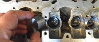
I decided to check the ADC on the mass air flow sensor. full article here. mayvaz.ucoz.ru/index/datc…hoda_vazdukhaju_dmvr/0-23 1. Turn on the tester in DC voltage measurement mode, and set the measurement limit to 2 Volts. We find in the sensor connector a yellow wire - output (closest to the windshield) and a green wire - ground (third from the same edge). These are the sensor pins we need. In systems of different years, colors may change (! and the connector may already be changed), only the location of the pins remains unchanged. To assess the condition of the mass air flow sensor, it is necessary to measure the voltage between the indicated terminals with the ignition on, but NOT starting the engine! The diameter of the tester probes allows you to penetrate through the rubber seals of the connector, along the specified wires, without disturbing their insulation, reaching the contacts themselves and without causing harm to the seals themselves. It will be useful to spray HP grease on the probes. Turn on the ignition, connect the tester, take readings. The same readings can be taken without a tester from the on-board computer display, if anyone has one. In the “voltage from sensors” parameter group. Designated Udmrv=…
2. Evaluate the results. The voltage at the output of a working sensor in the “out of the package” state is 0.996…1.01 Volts. During operation, it gradually changes and, as a rule, increases. By increasing this voltage, one can quite confidently judge the degree of “wear” of the sensor. A voltage within the above range is the best result of this test. Further options are possible: 1.01…1.02 - a completely working sensor, very good. 1.02…1.03 is also acceptable, but the sensor is no longer young. 1.03…1.04 - most of the resource is already behind, you can plan for a quick replacement. 1.04…1.05 - clearly a tired sensor, it has already served its purpose. If your budget allows, feel free to change it. 1.05...and higher are a source of problems, it’s high time to replace them.
Measured:
between the yellow and battery negative 1.052 V, (apparently the masses need to be cleaned) between the yellow and green wire 1.014 V. (sensor is live)
It is best to take the ground from the green wire, because this is exactly the voltage that the controller sees.
Here I found useful information on typical parameters. Made essentially as a note to myself.
For many novice diagnosticians and ordinary car enthusiasts who are interested in the topic of diagnostics, information about typical engine parameters will be useful. Since VAZ car engines are the most common and easiest to repair, we’ll start with them. What should you pay attention to first when analyzing engine operating parameters? 1. The engine is stopped. 1.1 Coolant and air temperature sensors (if equipped). The temperature is checked to ensure that the readings correspond to the actual engine and air temperatures. It is better to check using a non-contact thermometer. By the way, one of the most reliable in the injection system of VAZ engines are temperature sensors.
1.2 Throttle position (except for systems with an electronic gas pedal). The gas pedal is released - 0%, the accelerator is pressed - according to the opening of the throttle valve. We played with the gas pedal, released it - it should also remain 0%, while the ADC with a dpdz of about 0.5V. If the opening angle jumps from 0 to 1-2%, then as a rule this is a sign of a worn out valve. Less common are faults in the sensor wiring. With the gas pedal fully pressed, some units will show 100% opening (such as January 5.1, January 7.2), while others such as Bosch MP 7.0 will show only 75%. This is fine.
1.3 MAF ADC channel in rest mode: 0.996/1.016 V - normal, up to 1.035 V is still acceptable, everything above is already a reason to think about replacing the mass air flow sensor. Injection systems equipped with feedback from an oxygen sensor are able to correct, to some extent, incorrect readings of the mass air flow sensor, but there is a limit to everything, so you should not delay replacing this sensor if it is already worn out.
2. The engine is idling.
2.1 Idle speed. Typically this is 800 - 850 rpm with a fully warmed up engine. The idle speed value depends on the engine temperature and is set in the engine control program.
2.2 Mass air flow. For 8-valve engines, the typical value is 8-10 kg/h, for 16-valve engines - 7-9.5 kg/h with a fully warmed-up engine at idle. For the M73 ECU these values are slightly higher due to a design feature.
2.3 Length of injection time. For phased injection, the typical value is 3.3 - 4.1 ms. For simultaneous – 2.1 – 2.4 ms. Actually, the injection time itself is not as important as its correction.
ADC codes
ADC code parameters relate to analog sensors of the control system:
- Throttle position sensor
- temperature sensor
- Mass air flow sensor
- Sensor L-probe
- Potentiometer CO.
Physically, ADC codes reflect the voltage that the sensor produces. Typically, these parameters are used to test sensor circuits. If fault codes occur associated with a low or high signal level of such a sensor, then the control system operates in backup modes. In this case, the value of the parameter related to this sensor is selected either from the emergency table or calculated using specified formulas, for example, the coolant temperature with a faulty temperature sensor increases during engine operation.
If, during a physical change in the parameter measured by the sensor, the ADC code remains a constant value, then the electrical circuit connecting the sensor is inoperative.
ADC values are dimensionless, but for the user in scanner testers they are translated into the voltage that a particular sensor produces.
Therefore, using an ADC code, for example, from an L-probe sensor, you can more clearly evaluate the work in the feedback loop system to maintain the stoichiometric composition of the mixture. If the L-probe sensor is inoperative, then the ADC code is in the range of 0.4-0.7V.
The ADC code value (output voltage) from the throttle position sensor can indicate the lower limit at which the system detects sensor error. A throttle position equal to zero corresponds to a voltage from the sensor of 0.52 V.
When the ignition is on, the output voltage from the mass flow sensor (ADC code) should be 1.00V.
The temperature sensor, throttle position sensor, mass flow sensor are powered by a voltage of 5.00V, which is supplied by the control unit. If the control unit produces an unstable voltage, then the sensor readings will change and the behavior of the system in this case is unpredictable.
Optimal operation of a car engine depends on many parameters and devices. To ensure normal operation, VAZ engines are equipped with various sensors designed to perform different functions. What you need to know about diagnosing and replacing controllers and what are the parameters of sensors for VAZ injection engines is presented in the table in this article.
A friend called with this problem. Intermittent poor starting, won't hold revs until you've driven for a while, sometimes won't start at all without opening the throttle, stalls when going into neutral. I immediately assumed that it was either the air flow sensor or the speed sensor. The day of “diagnosis” has arrived. I connected, looked at the readings of the MAF ADC when the malfunction appeared and without a doubt sentenced him. I gave my spare MAF to a friend to finally verify the malfunction. He drove it for a week, said that everything was fine, installed a new one and was ready to give me mine. I collected and initialized it and it left. The next morning it couldn’t start without a boost of gas, it doesn’t hold the revs, the dynamics are near zero, after a short drive everything more or less returns to normal, in general everything is as it was... As it later turned out, this also happened to my MAF a couple of times, but he wrote it off for something else.. The day of diagnostics has come, part 2. What was checked (with an active malfunction): 1. DMRV connector. +12 is present during ignition and startup. +5 is present during ignition and startup. The resistance on the ground wire is less than 1 ohm. The readings on the signal wire are 1.001 - 1.007 V. The readings on the signal wire with the connector disconnected and the ignition on are ~5.6 kOhm. 2. The MAF ADC readings on the controller leg are 1.001 - 1.007 with the ignition on, according to diagnostics the same readings. When trying to start, the readings on the controller are ~1.060, according to the diagnostics 0.8xx - 0.9xx. 3. I removed the controller, there are minor traces of oxidation on the bottom of the board. Clearly condensation. Cleaned it of visible oxidation. There are no changes. 4. They sent me my M73, it was re-stitched for one by a competent person, I have the same engine. There are no changes. 5. Power and impulses are present at the forces. 6. Power and impulses are present on the mz. 7. The resistance between the computer ground and the body is less than 3 ohms during ignition and attempt to start. 8. All wiring harnesses are kept as far away from the starter as possible. 9. Dpkv working. When you try to start the diagnostics, the revs are visible. 10. Dprv worker. At idle, the pulse duration is 4+ ms. 11. Fuel pressure was checked by organoleptic method)) 12. There is no floating of the ADC of other sensors both during ignition and startup. 13. All sensor readings, when there is no malfunction, are more than normal. rxx position, air flow, air and coolant temperature, desired air flow, sinusoid and peaks of dc readings, load parameter. In general, absolutely everything.
Next, I will list the diagnostic readings that raised questions for me during an active malfunction (the engine is fully warmed up): 1. Intake air temperature 67. Outside it is no more than 18, the hood is open. 2. The signal from the only DC is inadequate. A torn sine wave, sometimes the graph sticks at the top or bottom. 3. The desired air flow rate is 40 kg/hour, with MVR 8. RPM ~1000. Also at this moment, the graph shows synchronicity between the readings of the desired flow rate and the pxx position, the pxx graph is 100-140 at this moment. 4. During a malfunction, if you release the pedal immediately after starting, the MRP drops to 6 kg/hour and the engine naturally stalls. There is also a stable gasoline fuse from the exhaust.
With all this, the next launch may go perfectly and absolutely all readings will be normal. Here are all our powers (c).
Purpose and explanation of the abbreviation
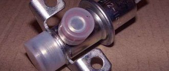
Flow meters, also known as volume meters or mass air flow meters (not to be confused with mass air flow meters and mass air flow sensors), are installed in diesel or gasoline-powered vehicles. The location of this sensor is not difficult to find, since it controls the air supply, you should look for it in the corresponding system, namely, after the air filter, on the way to the throttle valve (DZ).
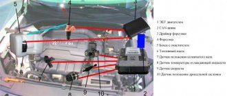
Installation location of mass air flow sensor on Gazelle 405
The device is connected to the engine control unit. In cases where the mass air flow sensor is in a faulty condition or is missing, a rough calculation can be made based on the position of the air flow sensor. But with this measurement method it is impossible to ensure high accuracy, which will immediately lead to excessive fuel consumption. This once again indicates the key role of the flow meter in calculating the fuel mass supplied through the injectors.
In addition to information from the mass air flow sensor, the control unit also processes data coming from the following devices: camshaft sensor (camshaft sensor), DD (knock meter), remote sensor, cooling system temperature sensor, acidity meter (lambda probe), etc.
This is interesting: What does g12 antifreeze mean?
Operating principle of ADC
So, we learned that an ADC converts an analog signal to a digital one. But how does he do it?
I will not tell you how this happens at the level of electronic circuits - this is a topic for electronics engineers. For developers of microcontroller devices (especially beginners), it is enough to know the general operating principle of the ADC in order to understand how the device they are creating will work and whether the accuracy of the measured analog value will be sufficient.
So, first of all, the ADC must convert the analog signal into a discrete one. What is it for?
As you already know, an analog signal is a continuous signal. That is, such a signal can take on an infinite number of values, and no processor will have enough “brains” to process all these values.
Therefore, the first task of the ADC is to divide the measured range into a finite number of values.
For example, we want to measure voltage in the range from 0 to 9 V. Let's say an accuracy of 1 V is enough for us. Then we divide this range into 10 values and find that each voltage value corresponds to the same number. That is, 0 is 0 V, 5 is 5 V, etc.
But what about, for example, a voltage of 4.3 V? No way. It is simply rounded up and the ADC converts it to the number 4. This simple example is shown in the figure below.
The question arises: how to measure high voltages? Or how to improve accuracy (for example, if we want to measure voltage with an accuracy of 0.1V)?
I’ll tell you about this too, but first about the ADC bit capacity.
Replacing the air flow sensor
To replace the sensor with your own hands, you need to prepare a shaped screwdriver and a “10” key.
The replacement procedure consists of the following steps:
- First you need to turn off the ignition and open the hood.
- Then you need to disconnect the negative terminal on the battery.
- At the next stage, you need to loosen the clamp with which the corrugation is attached to the mass air flow sensor.
- Next, remove the corrugation from the pipe.
- Then you need to bend the comb and disconnect the sensor connector.
Disconnecting the sensor connector
- Then, using a key set to “10”, you need to unscrew the sensor mounting bolts to the air filter housing.
- Now you can remove the mass air flow sensor.
- Installing the sensor yourself is carried out in the reverse order.
Thus, if the car stalls and has all the signs of a breakdown of the mass air flow sensor, then before you start repairing it, you should check the level of its signal, it should not be low, perform a full diagnosis of the car and repair all faulty components and parts.
It is important to undergo regular vehicle inspections and perform timely maintenance, then the parts and components will last longer.
Which oscilloscope to choose for car diagnostics
Let's consider the most convenient and informative devices.
USB Autoscope Postolovsky
In first place in the ranking of practitioners is the Postolovsky USB Autoscope IV oscilloscope. Has extensive diagnostic functions.
Advantages
- Professional scripts from Andrey Shulgin.
- User-friendly interface.
- Wide measurement range from 6 to 300 volts.
- Processing scripts automatically.
- Informative efficiency script for CSS cylinders, showing the operation of injectors and ignition systems.
- Test battery, generator, starter. Shows faults automatically. Easy process of reading characteristics: it is enough to have access to the positive or negative terminals of the battery.
- Cylinder pressure test. Shows the marks of the gas distribution system, whether the phases are correct. Detects a spun drive disk.
Complete documentation for operating the device. Scripts and connection diagrams are described in detail. There are video instructions on the manufacturer's website. Responsive support.
Motodoc 3
Second in the list of oscilloscope ratings for diagnosing a car of any brand is Motodok 3. It has similar characteristics.
Advantages and disadvantages
- Script by Andrey Shulgin for cylinder efficiency. There are some disadvantages to synchronization with some cars that have a weak signal from the crankshaft sensor. But this is offset by convenience and fast operation.
- Connections over any distance via RJ 45 cable.
- The quality of the picture during diagnostics, which is not unimportant when working.
- Detailed documentation on the manufacturer's website.
As an example, only two oscilloscopes for car diagnostics are shown. There are other devices: they differ in price and manufacturer, but the measurement principle is the same. The most important thing is to have experience in reading waveforms for each make of car.
Parallel ADCs
Most high-speed oscilloscopes and some high-frequency measurement instruments use parallel ADCs due to their high conversion speed, which can reach 5G (5*109) samples/sec for standard devices and 20G samples/sec for original designs. Typically parallel ADCs have a resolution of up to 8 bits, but 10-bit versions are also available.
Rice. 2 shows a simplified block diagram of a 3-bit parallel ADC (for high-resolution converters, the operating principle is the same). It uses an array of comparators, each of which compares the input voltage to an individual reference voltage. This reference voltage for each comparator is formed on a built-in precision resistive divider. The reference voltages start at half the least significant bit (LSB) and increase to each comparator in increments of VREF/23. As a result, a 3-bit ADC requires 23-1 or seven comparators. And, for example, for an 8-bit parallel ADC, 255 (or (28-1)) comparators will be required.
As the input voltage increases, the comparators sequentially set their outputs to a logical one instead of a logical zero, starting with the comparator responsible for the least significant bit. You can think of the converter as a mercury thermometer: as the temperature rises, the mercury column rises. In Fig. 2, the input voltage falls in the interval between V3 and V4, so the 4 lower comparators have a “1” at the output, and the upper three comparators have a “0” at the output. The decoder converts the (23-1) bit digital word from the outputs of the comparators into a binary 3-bit code.
Parallel ADCs are fairly fast devices, but they have their drawbacks. Due to the need to use a large number of comparators, parallel ADCs consume significant power and are not practical for use in battery-powered applications.
Delta-Sigma ADC (ΔΣ)
A newer technology is delta-sigma ADCs, which take advantage of DSP technology to improve amplitude-axis resolution and reduce the high-frequency quantization noise inherent in RPPs.
Sophisticated and powerful delta-sigma ADCs are ideal for dynamic measurements that require as much amplitude axis resolution as possible. They are used when working with sound and vibration, as well as in many advanced data acquisition systems.
Block diagram of a typical delta-sigma ADC
The DSP processor's low-pass filter virtually eliminates quantization noise, resulting in a near-ideal signal-to-noise ratio.
The implementation of these chips in data acquisition systems usually involves interface filtering and smoothing, which virtually eliminates the digitization of false signals.
When integrated at the analog interface level at the highest possible Nyquist sampling rate, and then dynamically through the DSP according to the selected sampling rate, the filtering/smoothing performance of these ADCs is simply excellent.
Features, diagnostics and replacement of elements of injection systems on VAZ cars
Below we will look at the main controllers!
Hall
There are several options for how you can check the Hall sensor of a VAZ:
- Use a known working device for diagnostics and install it instead of the standard one. If after replacement the problems in engine operation cease, this indicates a malfunction of the regulator.
- Using a tester, diagnose the controller voltage at its terminals. During normal operation of the device, the voltage should be from 0.4 to 11 volts.
The replacement procedure is performed as follows (the process is described using the example of model 2107):
- First, the switchgear is dismantled and its cover is unscrewed.
- Then the slider is dismantled; to do this, you need to pull it up a little.
- Remove the cover and unscrew the bolt that secures the plug.
- You will also need to unscrew the bolts that secure the controller plate. After this, the screws that secure the vacuum corrector are unscrewed.
- Next, the retaining ring is dismantled and the rod is removed along with the corrector itself.
- To disconnect the wires, you will need to move the clamps apart.
- The support plate is pulled out, after which several bolts are unscrewed and the manufacturer dismantles the controller. A new controller is being installed, assembly is carried out in the reverse order (the author of the video is Andrey Gryaznov).
Speeds
The following symptoms may indicate a failure of this regulator:
- at idle, the speed of the power unit floats, if the driver does not press on the gas, this can lead to an arbitrary shutdown of the engine;
- the speedometer needle readings float, the device may not work as a whole;
- fuel consumption has increased;
- the power of the power unit has decreased.
The controller itself is located on the gearbox. To replace it, you only need to jack up the wheel, disconnect the power wires and remove the regulator.
Fuel level
The VAZ or FLS fuel level sensor is used to indicate the remaining volume of gasoline in the fuel tank. Moreover, the fuel level sensor itself is installed in the same housing with the fuel pump. If it malfunctions, the readings on the dashboard may be inaccurate.
The replacement is done like this (using the example of model 2110):
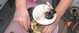
- The battery is disconnected and the rear seat of the car is removed. Using a Phillips screwdriver, unscrew the bolts that secure the fuel pump hatch and remove the cover.
- After this, all wires leading to it are disconnected from the connector. It is also necessary to disconnect all the pipes that are supplied to the fuel pump.
- Then the nuts securing the clamping ring are unscrewed. If the nuts are rusty, treat them with WD-40 before unscrewing.
- Having done this, unscrew the bolts that directly secure the fuel level sensor itself. The guides are pulled out from the pump casing, and the fasteners need to be bent with a screwdriver.
- At the final stage, the cover is dismantled, after which you will be able to gain access to the FLS. The controller is replaced, the pump and other elements are assembled in the reverse order of removal.
Photo gallery “Changing the FLS with your own hands”
Idle move
If the idle speed sensor on a VAZ fails, this is fraught with the following problems:
- floating speed, in particular, when additional voltage consumers are turned on - optics, heater, audio system, etc.;
- the engine will start to stall;
- when the central gear is activated, the engine may stall;
- in some cases, failure of the IAC can lead to body vibrations;
- the appearance of a Check indicator on the dashboard, but it does not light up in all cases.
Checking and repairing at home
There are eight ways to independently check amplitude and frequency mass flow sensors.
Method No. 1 - disabling the air flow meter
The method consists of disconnecting the sensor from the fuel system of the car and checking the functionality of the system without it. To do this, you need to disconnect the device from the connector and start the engine. Without a mass air flow sensor, the controller receives a signal to switch to emergency operation mode. It prepares the air-fuel mixture only based on the throttle position. If the car moves faster and does not stall, it means that the device is faulty and requires repair or replacement.
Method No. 2 - flashing the electronic control unit
If the standard firmware has been changed, then it is unknown what reaction of the controller is programmed in it in case of an emergency. In this case, you should try to insert a 1mm thick plate under the throttle stop. The turnover should increase. Now you need to pull out the chip from the air flow meter. If the power unit continues to work, then the cause of the malfunction is the firmware.
Method No. 3 - installing a working sensor
Install a known good part and start the engine. If after replacement it begins to work better, the motor does not stall, then replacement or repair of the device is required.
Method No. 4 - visual inspection
To do this, use a Phillips screwdriver to unscrew the clamp holding the air collector corrugation. Then you need to disconnect the corrugation and inspect the internal surfaces of the air collector corrugation and the sensor.
Inspection of duct corrugation
There should be no traces of oil or condensation on them, the surfaces should be dry and clean. If you do not take care of the air filter and change it rarely, then dirt can get on the sensitive element of the sensor and cause it to break. This is the most common malfunction. Traces of oil may appear in the flow meter if the oil level in the crankcase is high, or if the oil sump of the crankcase ventilation system is clogged. If necessary, you need to clean the surfaces using special cleaning products.
Method No. 5 - checking the mass air flow sensor with a multimeter
To do this, you need to turn on the tester in a mode in which constant voltage is checked. The limit value for measurements should be set to 2V.
DMRV operation diagram
- The yellow wire is located closer to the windshield. It serves as an input for a signal from the flow meter.
- The white-gray wire is the sensor voltage output.
- The black and pink wire leads to the main relay.
- The green wire is used to ground the sensors, that is, it goes to ground.
The wires may have different colors, but their location is unchanged. To check, you need to turn on the ignition, but do not start the car. The red probe from the multimeter must be connected to the yellow wire, and the black one must be connected to ground, that is, to the green wire. We measure the voltage between these two outputs. Multimeter probes make it possible to connect without disturbing the insulation of the wires.
On the new device, the output voltage ranges from 0.996 to 1.01 V.
During operation, this voltage gradually increases and by its value one can judge the wear of the flow meter:
- if the sensor is in good condition, the voltage is from 1.01 to 1.02 V;
- in satisfactory condition - from 1.02 to 1.03 V;
- the sensor resource ends if the voltage is in the range from 1.03 to 1.04 V;
- a value in the range from 1.04 to 1.05 indicates a near-death state; if there are no contraindications, then you can continue to use the sensor;
- if the voltage exceeds 1.05 V, the mass air flow sensor requires replacement.
ADC flow meter readings
Diagnostics of the mass air flow sensor "Tseshkoy" is not difficult and can be done with your own hands.
If there is dirt on the removed sensor, you can clean it yourself. You can use WD-40 to wash it. To clean the mass air flow sensor, you must first remove the pipe from it, and then dismantle the device itself. Inside the device there is a mesh and several wires - sensors.
They need to be sprayed with cleaning agent and washed. Then let the liquid dry. If dirt remains, the procedure should be repeated. You need to clean the pipe with the same product. It must be free of dirt and oil stains. After replacing the air filter, all parts must be returned to their place. After the cleaning procedure, the device’s functionality can be restored to 80%, the error about the reduced sensor signal level disappears (the author of the video is “24 hours”).
Flushing the sensor will help avoid costly repairs.
Method No. 6 - checking with a scanner
- Install a diagnostic program on your phone (smartphone), tablet or laptop computer (for example, Torque Pro, Opendiag, BMWhat, OBD Auto Doctor).
- Connect your mobile device or laptop to the diagnostic connector located on the vehicle's electronic control unit using a special cable, Bluetooth channel.
- Launch the diagnostic utility on your phone (smartphone) or computer.
- Wait until the program finishes scanning all vehicle components. As a result, the utility will check the serviceability of each vehicle unit.
- Decipher the error codes that the program will show after the diagnostics are completed.
To perform this method, testers are used:
Method No. 7 – checking by Vasya the Diagnosticist
To identify a malfunction of the mass air flow sensor without removing it from the car, you need to:
- Install a program called “VASYA diagnostician” on your laptop (laptop) and run it.
- Connect the adapter to the vehicle's diagnostic port.
- Select the item “Electronics 1” or “01 – Engine electronics” from the “Control unit” tabs to connect to the vehicle’s control unit.
- Go to “Custom Groups”.
- Select 211, 212 (passport value) and 213 (current value).
- Compare current indicators with passport data. If the deviations are high, then it is necessary to replace the mass air flow sensor.
Method No. 8 - using a motor tester
This method is used to test frequency-type flowmeters.
To check the mass air flow sensor with a motor tester (oscilloscope), you need to connect it to the sensor (depending on the car brand) and start the engine.
Mass air flow sensor check parameters:
- transient time when the ignition is on;
- air consumption readings at idle and a sharp increase in engine speed;
- voltage in the sensor network.
The output data is individual for different types of engines. Before diagnosis, you should check the current indications with an official representative.
ADC with parallel conversion of input analog signal
In the parallel method, the input voltage is simultaneously compared to n reference voltages and determined between which two reference voltages it lies. In this case, the result is obtained quickly, but the scheme turns out to be quite complex.
Operating principle of the ADC (Fig. 3.93)
When Uin = 0, since for all op-amps the voltage difference (U+ − U−) < 0 (U+, U− are voltages relative to the common point of the non-inverting and inverting input, respectively), the voltages at the output of all op-amps are equal to −Epit at the outputs of the encoding converter ( KP) Z0, Z1, Z2 are set to zero. If Uin > 0.5U, but less than 3/2U, only for the lower op-amp (U+ − U−) > 0 and only at its output does the voltage +Epit appear, which leads to the appearance of the following signals at the outputs of the CP: Z0 = 1, Z2 = Zl = 0. If Uin > 3/2U, but less than 5/2U, then the voltage +Epit appears at the output of the two lower op-amps, which leads to the appearance of code 010 at the outputs of the CP, etc.
Watch an interesting video about the operation of the ADC:
ADC characteristics
There are different ADCs with different characteristics. The main characteristic is the bit depth. However, there are others. For example, the type of analog signal that can be connected to the ADC input.
All these characteristics are described in the documentation for the ADC (if it is designed as a separate chip) or in the documentation for the microcontroller (if the ADC is built into the microcontroller).
In addition to the bit capacity, which we have already discussed, we can name several more basic characteristics.
Least significant bit (LSB) – least significant bit (LSB) . This is the smallest input voltage that can be measured by the ADC. Determined by the formula:
1 LSB = Uop / 2P
Where Uop is the reference voltage (indicated in the ADC specifications). For example, with a reference voltage of 1 V and a bit width of 8 bits, we get:
1 LSB = 1 / 28 = 1 / 256 = 0.004 V
Integral Non-linearity – integral non-linearity of the ADC output code . It is clear that any transformation introduces distortions. And this characteristic determines the nonlinearity of the output value, that is, the deviation of the ADC output value from the ideal linear value. This characteristic is measured in LSB.
In other words, this characteristic determines how “curve” a line on the output signal graph can be, which ideally should be straight (see figure).
Absolute precision . Also measured in LSB. In other words, this is the measurement error. For example, if this characteristic is +/- 2 LSB, and LSB = 0.05 V, then this means that the measurement error can reach +/- 2 * 0.05 = +/- 0.1 V.
The ADC also has other characteristics. But for starters, this is more than enough.
Description of ADS1115 registers
The ADC has only 4 internal registers, all registers are 16-bit, respectively, for each write/read session, 2 information bytes are transmitted via the I2C interface (except for the register address byte). The registers are described in the table below:
| Address | Name | Register description |
| 0x00 | Conversion register | Conversion result storage register |
| 0x01 | Config register | Configuration register |
| 0x02 | Lo_thresh register | Setpoint register, minimum value |
| 0x03 | Hi_thresh register | Setpoint register, maximum value |
The configuration register is used to control the ADC; the register is described in the table below:
| Bit | Bit name | Bit value | Description |
| 15 | OS. The bit defines the state of the device and can only be written in low power mode | For recording | |
| 0 | No effect | ||
| 1 | Start conversion, for single conversion mode (low consumption) | ||
| For reading | |||
| 0 | Conversion in progress | ||
| 1 | Conversion complete | ||
| 14-12 | MUX. Multiplexer setup | 000 | AINp=AIN0 and AINn=AIN1 (default) |
| 001 | AINp=AIN0 and AINn=AIN3 | ||
| 010 | AINp=AIN1 and AINn=AIN3 | ||
| 011 | AINp=AIN2 and AINn=AIN3 | ||
| 100 | AINp=AIN0 and AINn=GND | ||
| 101 | AINp=AIN1 and AINn=GND | ||
| 110 | AINp=AIN2 and AINn=GND | ||
| 111 | AINp=AIN3 and AINn=GND | ||
| 11-9 | P.G.A. Amplifier Gain | 000 | FS=±6.144 V |
| 001 | FS=±4.096 V | ||
| 010 | FS=±2.048 V (default) | ||
| 011 | FS=±1.024 V | ||
| 100 | FS=±0.512 V | ||
| 101 | FS =±0.256 V | ||
| 110 | FS =±0.256 V | ||
| 111 | FS =±0.256 V | ||
| 8 | MODE. Operating mode | 0 | Continuous transformation |
| 1 | Single conversion, low consumption mode (default) | ||
| 7-5 | D.R. Sampling frequency | 000 | 8 Hz |
| 001 | 16 Hz | ||
| 010 | 32 Hz | ||
| 011 | 64 Hz | ||
| 100 | 128 Hz (default) | ||
| 101 | 250 Hz | ||
| 110 | 475 Hz | ||
| 111 | 860 Hz | ||
| 4 | COMP_MODE. Comparator type | 0 | Comparator with hysteresis (default) |
| 1 | Comparator without hysteresis | ||
| 3 | COMP_POL. Comparator polarity | 0 | Low active level (default) |
| 1 | High active level | ||
| 2 | COMP_LAT. Comparator mode | 0 | Comparator without latch (default) |
| 1 | Latch Comparator | ||
| 1-0 | COMP_QUE. Comparator control | 00 | Setting the output signal after one conversion |
| 01 | Setting the output signal after two conversions | ||
| 10 | Setting the output signal after four conversions | ||
| 11 | Comparator disabled (default) |
Parameters of ADC sensors VAZ
- Registration
- Entrance
- To the beginning of the forum
- Forum Rules
- Old design
- FAQ
- Search
- Users
Sorry for maybe stupid questions
As I understand it, this is a crimp on the sensor masses, located 20cm from the ECU connector?
And here is the “wire from the ECU to the 3rd contact of the mass air flow sensor”
on the diagnosis and according to the tester (3rd and 5th contacts of the air flow sensor) 0.996
When driving at low throttle, when releasing the gas, driving at idle and when switching, it jerks. It seems like symptoms of a mass air flow sensor.
Symptoms of a problem
The mass air flow sensor is located in the air duct near the air filter. It is designed to determine the amount of incoming air. Depending on its readings, the control unit will show how much fuel is needed to form a high-quality fuel mixture. The normal ratio is 1:14. Therefore, the quality of the fuel-air mixture depends on the correct readings of the flow meter.
The high-quality operation of the mass air flow sensor depends largely on the cleanliness of the air filter. Therefore, if symptoms of a malfunction of the mass air flow sensor appear, you should first check the air filter before making repairs. The flow meter is usually beyond repair. If it is faulty, it is replaced with a new device. But its cost is quite high, so you should first make sure that the causes of the problems are in the sensor and not in other malfunctions of the machine.
The signal for diagnosis is the following symptoms of a malfunction of the mass air flow sensor:
- Check Engine appears on the instrument panel;
- an error is displayed indicating a low level of the mass air flow sensor signal;
- the engine starts poorly when cold, accelerates very slowly, stalls, and its power drops;
- high level of fuel consumption;
- the engine is unstable at idle;
- the engine stalls when changing gears;
- The rpms are either high or low.
There are other symptoms of a “dying” sensor. For example, it may have cracks in the corrugated hose that connects the throttle body to the sensor. If the engine stalls, there may be a power problem or damaged wiring. This is a signal to check the electrical wiring. If malfunctions are detected, the machine's electrical system must be repaired.
Term: ADC
Analog-to-digital converter (ADC) is a device that converts an input analog signal into a digital signal (digital binary code). For tasks of measuring the value of a signal at an arbitrary point in time, an asynchronous mode of operation with an ADC with single analog-to-digital conversions that are not strictly time-bound is used. For tasks of measuring the functional dependence of changes in an analog signal, the synchronous operating mode of the ADC is used. The synchronous mode of operation of the ADC without missing data over an arbitrarily large time interval is also called streaming mode. Synchronous ADCs, as a rule, support the frame-by-frame principle of data acquisition, when digitized measurement reports form conditional frames with a specified number of samples corresponding to specified measurement channels.
The ADC is an integral part of the data acquisition system.
Main parameters of the ADC:
- Signal input range (measurement range).
- Conversion frequency [Hz] – repetition rate of analog-to-digital conversions. In DSP terminology, the ADC conversion frequency is called the sampling frequency of the signal in its digital representation.
- Conversion period [s] = [1/Hz] – the reciprocal of the conversion frequency. In DSP terminology, the conversion period of the ADC is the conversion period of the signal in its digital representation. For asynchronous ADCs, the conversion time is standardized.
- ADC bandwidth [Hz]…[Hz]. This is the range of signal frequencies that the converter passes at a signal level of -3 dB.
- ADC capacity is the number N of binary bits of the converter, while the number of signal quantization levels in the digital representation of the ADC is equal to 2N.
- ADC conversion channel signal-to-noise ratio [dB]
- ADC technology. Typical representatives: successive approximation ADC, sigma-delta ADC.
- Inter-channel transmission [dB].
The upper frequency of the passband of a successive approximation ADC can be significantly greater than the conversion frequency of the ADC, and the upper frequency of the passband of the sigma-delta ADC does not exceed half the conversion frequency of the ADC.
ADCs differ in the types of inputs. ADCs with a voltage input are more common, and less commonly with a current or charge input.
Multichannel ADCs are built on the principle of independent parallel ADC channels or on the principle of channel-switched ADCs.
ADCs with channel switching are divided into ADCs with an input channel switch (in which the switching process occurs directly in the measuring circuit) and into ADCs with an internal switch, for example, like the E20-10 (in which the switching process occurs internally and does not affect the measuring circuit).
An important characteristic of an ADC is the presence of galvanic isolation of the input signal circuit. For an ADC with a voltage input, an important characteristic is the type of voltage input: differential input, input with common ground.
According to consumer properties, all ADCs can be divided into general-purpose ADCs and specialized ADCs. For general use, ADCs that have differential voltage inputs and galvanic isolation (LTR11, LTR24-1) are most suitable. Specialized ADCs include converters that have a special input for a specific sensor (for example, a strain gauge - LTR212, LTR216, or an ICP sensor - LTR25), or are designed to perform special functions (for example, frequency measurement - LTR51). At the same time, general-purpose ADCs may have specialized measurement modes (channels) (for example, resistance measurement with the LTR114 module).
A special group includes ADCs based on voltage-frequency converters for measuring constant or slowly varying voltage or current (for example, H-27x).
ADC channels, supplemented by an interface with a PC, are part of data acquisition systems - examples of typical implementations were mentioned above.
( 2 ratings, average 4.5 out of 5 )
What does a faulty air flow sensor cause?
Operating an engine with an inoperative/faulty flow meter causes detonation of the fuel mixture in the combustion chamber. This affects the operation of the crank mechanism (crank mechanism) and destroys the piston surface, which can cause a “wedge” in the engine.
What indications should a working mass air flow sensor give?
The voltage of the analog-to-digital converter (ADC) of the flow meter when the engine is not running should be 0.996 V. Indicators of 1.016 and 1.025 V are acceptable, but if they reach more than 1.035 volts, it means that the sensing element of the mass air flow sensor is clogged.
To accurately determine the degree of deviation of the operating flow meter values from normal values, it is necessary to evaluate the engine operation at different speeds.
For example, for an injection 1.5-liter VAZ 2111 engine, if it is in good condition, at idle (860–920 rpm) the correct readings are 9.5–10 kg/hour, and at 2 thousand rpm - 19 –21 kg/hour. If the flow meter at 2 thousand rpm shows about 17–18 kg, then the car will drive stably. If the values are from 22 to 24 kg/hour, then the vehicle will move steadily, but the fuel consumption per 100 km will be approximately 10–11 liters. In addition, the car will have difficulty starting in cold weather due to fuel overflow when the engine warms up.
Microcontroller C8051F064
The C8051F064 chip is a high-speed 8-bit microcontroller for combined analog and digital signal processing with two integrated 16-bit SAR ADCs.
Built-in ADCs can operate in single-wire and differential modes with maximum throughput of up to 1M samples/sec. In Fig. 17 shows the main characteristics of the ADC of the C8051F064 microcontroller. To independently evaluate the digital and analog processing capabilities of the C8051F064, you can use the inexpensive C8051F064EK evaluation kit (Figure 18). The kit contains a C8051F064-based evaluation board, USB cable, documentation, and software for testing the analog dynamic and static characteristics of an integrated high-precision 16-bit ADC. VDD= 3.0 V, AV+ = 3.0 V, AVDD = 3.0 V, VREF = 2.50 V (REFBE=0), -40 to +85° unless otherwise noted
| Options | Conditions | Min. | Typical | Max. | Units |
| DC characteristics | |||||
| Bit depth | 16 | bit | |||
| Integral nonlinearity | Single wire | ±0.75 | ±2 | LSB | |
| Single wire | ±0.5 | ±1 | LSB | ||
| Differential nonlinearity | Guaranteed monotony | ±+0.5 | LSB | ||
| Additive error (offset) | 0.1 | mV | |||
| Multiplicative bias | 0.008 | %FS | |||
| Temperature gain | 0.5 | ppm/°C | |||
| Dynamic characteristics (Sampling rate 1 Msps, AVDD, AV+ = 3.3 V) | |||||
| Signal/noise and distortion | Fin = 10 kHz, single wire | 86 | dB | ||
| Fin = 100 kHz, single wire | 84 | dB | |||
| Fin = 10 kHz, differential | 89 | dB | |||
| Fin = 100 kHz, differential | 88 | dB | |||
| Total harmonic distortion | Fin = 10 kHz, single wire | 96 | dB | ||
| Fin = 100 kHz, single wire | 84 | dB | |||
| Fin = 10 kHz, differential | 103 | dB | |||
| Fin = 100 kHz, differential | 93 | dB | |||
| Harmonic-free dynamic range | Fin = 10 kHz, single wire | 97 | dB | ||
| Fin = 100 kHz, single wire | 88 | dB | |||
| Fin = 10 kHz, differential | 104 | dB | |||
| Fin = 100 kHz, differential | 99 | dB |
References.
- https://www.wbc-europe.com/en/services/pim_application_guide.html
- www.silabs.com
Connection diagram for air flow sensor 2114
A common cause of incorrect operation of the mass air flow sensor is the failure of electronic components, which increases the sensor’s response time to changes in air flow. A working sensor monitors changes at a speed of 0.5 ms, and if it breaks down, the response time increases by 20-30 times. The defect is detected only by recording the operation graph with an oscilloscope. Such a sensor cannot be repaired; it must be replaced with a new one.