Purpose of the lubrication system and functions performed
Engine lubrication system
The internal combustion engine of any vehicle consists of many elements that interact very aggressively with each other during its operation. Due to their constant movement inside the installation, a high friction force arises, leading to large power losses and, as a consequence, increased fuel consumption. Prolonged operation “dry” can even lead to jamming of the power unit: increased interaction of parts will lead to heating of their surfaces and further expansion; as a result, this will reduce the working gaps of the structure and will lead to their filling with metal shavings formed as a result of the destruction of the main elements.
To prevent this condition and extend its useful life, the internal combustion engine is equipped with a lubrication structure that facilitates the movement of parts, creating a strong protective film around the elements of the internal combustion system.
Thus, the lubrication system of any two-stroke or four-stroke engine performs the following number of functions:
- Reducing the friction force between working elements;
- Cooling their surfaces;
- Reduced engine operating temperature;
- Removal of metal shavings and contaminants outside the working space of the installation;
- Prevention of rapid wear, destruction and coking of parts;
- Ensuring the required working fluid pressure for efficient operation of the internal combustion engine (changing the timing of the gas distribution mechanism, adjusting the operating valve clearances with hydraulic compensators).
Modern oil in an old engine
The term “old engine” should not be understood as the date of its actual production, not the mileage, but the date of its development. Older engines used construction materials very different from the composite alloys used today.
When selecting oil for an old engine, take into account that corrosion inhibitors intended for aluminum are absolutely useless for cast iron. Accordingly, this affects the total duration of operation of the internal combustion engine.
Lubrication system design
We figured out what this system is intended for, now it’s time to study its structure. Each car has its own lubrication system, so its design components may differ significantly from each other. It may be supplemented with some elements, or it may not have the following components at all, but, as a rule, modern systems are characterized by the presence of the following elements:
- Carter with pallet. The sump is the lowest part of the power plant. It is attached to the crankcase using bolts and gaskets and serves as a kind of “storage” for the working fluid. In the sump, it cools and “calms down” - thanks to special partitions, the engine oil stops agitating when the vehicle moves over uneven surfaces.
- Filter. The filter element in the lubrication system serves as a place where the working fluid “brings” debris that impairs the performance of the power plant. This can be soot, soot, dust from outside, metal shavings and other pollutants. Once the filter is clogged, the engine oil begins to quickly lose its properties due to an excessive amount of dirt particles, which leads to a loss of power performance of the entire vehicle. In order to prevent harmful consequences for the internal combustion engine, it is necessary to promptly replace the working fluid and do not forget to change the filter elements.
Oil filter
- Oil pump. Without a pump, the operation of the mechanism would not be possible: it is the pump that creates the required pressure inside the installation and “forces” the working fluid to act on the mechanisms. There are two types of pumps used in cars - gear and rotary. The first type of units provides oil supply with constant pressure, while the rotary unit allows for changing the supply force. A pressure of 2 to 16 atmospheres is created inside the engine compartment.
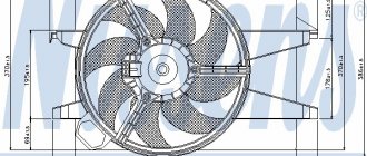
- Radiator. This element of the engine lubrication system ensures cooling of the engine oil. Moreover, cooling can be of two types - liquid and air.
- Reducing and bypass valves. These elements allow you to reduce blood pressure if it exceeds the established norm. These elements are installed inside the power plant next to the oil pump, filter, etc. and are activated by the activation of special sensors. For example, when the filter is clogged, the bypass valve allows working fluid to bypass it to prevent the entire engine from stopping.
- Oil pressure and temperature sensors. It is thanks to them that the on-board computer learns about the performance of the system. The pressure sensor is installed in the central line and measures the main parameter. If it deviates from the norm, an indicator lights up on the car’s dashboard.
- Lubrication channels. It is not difficult to guess what these elements are used for: they provide the supply of motor fluid to interacting mechanisms.
- Main highway. Carries out the flow of oil from the pump to the filter. Thanks to the large cross-section, the line maintains fluid circulation at the required level. Also, thanks to the line, the crankshaft bearings are lubricated.
Depending on the design features of the vehicle, a modern lubrication unit can be supplemented with other components.
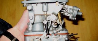
Valve N428
The oil pump control valve N428 is designed to regulate the pressure on the control piston. Depending on the pressure on the piston, the position of the stator and the volume of the suction chamber changes. Part of the oil from the discharge cavity is always supplied to the control line to valve N428. At the command of the engine control unit, power is supplied to the valve and oil is supplied to the control piston. By design, the N428 is an electrically controlled hydraulic 3/2 way valve.
Types of lubrication systems
Despite the fact that all devices in the lubrication system perform the same functions, it can be of three types:
- oil spray system,
- pressure fluid supply system,
- combined system.
The first type has a fairly simple device: here the oil gets to the working parts thanks to special scoops installed on the crank heads of the connecting rods. The liquid captured from the pan is dispersed throughout the working area in the form of oil mist.
The disadvantage of this method of oil distribution is associated with uneven lubrication of structural elements due to periodic changes in its level in the lower engine container - the sump.
The volume of working fluid constantly changes with increasing crankshaft speed, tilting the vehicle and in aggressive driving mode. The scoops cannot control the amount of liquid splashing, so the motor periodically begins to experience oil starvation or, conversely, choke from an excessive amount of liquid.
The second type of system involves a continuous supply of engine oil to all elements of the installation. The lubricant composition is collected in the installation crankcase, and then supplied through special channels to the working unit. After completing the set goals, the oil flows into the oil pan. If in the first type of system it is not possible to adjust the amount of oil, then in the second type such adjustment is quite possible. Despite the fact that the system provides an economical and rational distribution of technical fluid, it has not received widespread use - it involves too costly and labor-intensive production.
Engine oil in the engine
By combining the technologies of spraying and supplying oil under pressure, engineers were able to create a combined type of lubricant distribution: protective fluid is supplied to the main structural components that are most susceptible to wear under pressure, while the rest of the mechanisms, operated in quieter conditions, are sprayed with oil by splashing.
The combined system involves the use of a wet and dry sump. A wet sump means that it is constantly filled with working fluid. The simplicity and reliability of the principle allowed it to become widespread: almost all standard cars are equipped with a similar system. However, it has some not entirely pleasant drawbacks: if air or a fuel mixture gets into the crankcase, the oil composition begins to foam and lose its lubricating properties. As a result, the internal combustion engine remains without the proper level of protection. To prevent such an unfavorable effect, diagnostics of the vehicle system for depressurization should be carried out regularly.
A dry sump is ensured by the presence of a special tank in the power plant, into which all waste fluid flows. Here, mixing it with air and the fuel mixture is simply impossible. The advantages of such a system include the stability of its operation when the vehicle passes obstacles with a large angle of inclination. The dry sump principle is used on racing cars, sports cars and some SUVs.
Additives
In fact, the properties of motor oils are ensured by a complex of additives. The base base of any liquid lubricant is only 70-95% of the total volume of the canister; the remaining volume is achieved through various additives.
The use of additives provides not only viscosity and operational stability. Additives help minimize the formation of sludge and carbon deposits, as well as minimize possible damage when such deposits get into the engine channels and rubbing vapors.
Key5 ingredients affecting the quality of the lubricating fluid:
- Viscosity Control Additives
- Detergent additives for flushing the system and removing wear debris
- corrosion inhibitors - protection against corrosion of metal products
- anti-wear components - for example, zinc additives required to provide solid lubrication of rubbing pairs when an oil stain drains
- friction modifiers designed to reduce fuel consumption by reducing the friction coefficient of pairs (for example, graphite, molybdenum)
- anticoagulating additives that prevent the formation of paraffin solid compounds at low temperatures.
- foam inhibitors that dampen foam formation that occurs due to the crankshaft churning fluid in the engine crankcase.
Operating principle of the lubrication structure
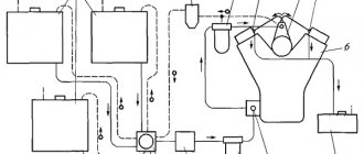
Lubrication system operation
The principle of operation of the lubrication system is the uninterrupted supply of working fluid to all elements subject to mechanical wear.
The operation diagram of the lubrication system is as follows. During startup of the power plant, the oil receiver captures the required amount of oil from the oil pan and directs it to the oil pump. The pump, in turn, sets the fluid force and speed with which it will circulate cyclically through the system. After the pump, the oil enters the filter and undergoes thorough cleaning. As mentioned earlier, if this element of the chain is dirty, the bypass valve will allow the working lubricant to bypass the filter element. After it, the fuel and lubricants are sent to the bearings of the connecting rods and crankshaft, the camshaft supports and pins, and the rocker arms of the valve drive. If there is a turbocharger, oil is also distributed onto its shaft.
The working mixture enters the inner sides of the cylinders through holes in the connecting rod head. Here it ensures unhindered movement of oil scraper and compressor rings and reduces wear on the cylinder walls. After lubricating the elements of the power plant, the waste liquid is returned back to the car sump, where, under the influence of a continuously rotating crank mechanism, it is sprayed over the remaining elements of the system.
Oil for gasoline internal combustion engines and diesel engines
Motor oils for passenger cars are divided into motor oils for gasoline engines and diesel engines. Modern petrochemical standards imply the possibility of such an application. But for older internal combustion engines, the operating temperature schedules differ and gasoline oil is not applicable for diesel engines.
It will not ensure normal operation of the mating rubbing surfaces. As for the temperature conditions of internal combustion engines currently produced, they approximately coincide, and this allows the operation of technical fluids in both types.
Possible problems with the system and how to resolve them
Some engine problems in the lubrication system may occur unexpectedly, even if you recently repaired the car or carried out its maintenance. Let's list the main problems and look at ways to solve them:
| Type of malfunction | Cause | Elimination |
| The oil pressure sensor does not light up when the ignition is turned on. | 1. The indicator is burnt out | 1. Replace the gauge bulb in the dashboard |
| 2. Damage to the wire, oxidation of the connector | 2. Inspect the connection and, if necessary, replace the wire | |
| 3. Failure of the oil pressure sensor | 3. Replace the sensor with a new one | |
| The oil pressure indicator lights up at idle and turns off when the speed increases. | Low oil pressure due to overheating. The cooling system is not working properly | “Drive” the car at high speeds for 15-20 minutes to cool the engine; Carry out a diagnostic inspection of the cooling system performance |
| The indicator on the dashboard lights up at increased engine speeds | Reducing valve faulty | Using a dipstick, check the engine oil level in the car and, if necessary, replace the pressure relief valve |
| The indicator is constantly on | 1. Too low amount of oil fluid | 1. Check the oil level and add if necessary |
| 2. The pump does not work, the oil pump channel is dirty | 2. Clean or replace the pump | |
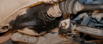
| High oil consumption | Wear of cylinders, piston rings, valve stem seals, sealing elements | Inspect the engine system and eliminate the cause of the leak. |
Oil pump
Oil pressure is created by the oil pump. Typically gear-type. Thanks to minimal gaps between liners, shaft journals, and calibrated holes. Designed for spraying oil. The system maintains the required operating oil pressure.
Any hydraulic system has the same operating principle. The oil pump will not begin to create pressure until the oil meets resistance. Or in our case, as long as there is resistance to oil in the liners and calibrated holes, the pump creates the required operating pressure.
Motor oils for gas engines
A separate type of liquid lubricant, developed taking into account the absence of liquid fuel that dilutes the oil and the impossibility of using fuel as a coolant - oil for use in engines running on liquefied gas. Such oils are designated SHC and have different viscosities according to SAE standards.
A feature of this oil is increased adhesion to metals, which is especially important at the points of contact between the piston rings and the cylinder walls. In some cases, such products are classified as industrial lubricants, although they are successfully used on heavy automotive equipment.
Other oils for filling into automobile engines in emergency conditions
In case of emergency and it is not possible to fill the recommended lubricant, short-term use of liquid lubricants used for marine and diesel engines, aviation and even turbine oils is possible.
The use of non-recommended types of oils is possible only in emergency situations when it is impossible to tow the car or the towing service is unavailable. An emergency mileage of no more than 50 km is possible with mandatory flushing of the lubrication channels before changing the oil.
After filling with oils not intended for use in automobile internal combustion engines, it is necessary to replace sealing rubber products, since additives in industrial and industrial oils destroy the structure of the material. As an addition, after operation with different oils, it is recommended to perform a partial overhaul of the engine with defective crankshaft journals.
Didn't find the information you are looking for? on our forum.