Signs of an upcoming VAZ valve adjustment are a drop in engine power at high/low speeds and a characteristic metallic knock. , the seat and the valve itself will . And too large gaps provoke the same tapping.
Adjusting valves on a VAZ 2107 is considered a moderate task—novice auto repair workers should trust experienced mechanics.
The adjustment process itself on a VAZ 2107, be it a carburetor or an injector, occurs the same way. The differences lie in how to remove the cylinder head cover and set the pistons to top dead center - on injection-powered "sevens" you won't be able to get in with a ratchet.
In any case, to adjust the valves on the VAZ 2107 you will need :
- open-end wrenches for 13 and 17;
- probe 0.15 mm thick.
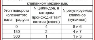
| The procedure for adjusting valves on a VAZ 2107 | ||
| TDC cylinder | Crankshaft rotation degree | Valves |
| 4 | 0 | 6 and 8 |
| 2 | 180 | 4 and 7 |
| 1 | 360 | 1 and 3 |
| 3 | 540 | 2 and 5 |
Why do you need valve adjustment?
In any automobile engine, the opening of the valves is necessary to fill the cylinders with the air-fuel mixture, and after they are hermetically sealed, combustion occurs in the chambers and the working cycle is completed. If you do not set the specifications, make them less than the required norm, or remove them altogether, there will be no tightness, and accordingly, the valves will not close completely, and the fuel mixture will not burn completely.
With increased clearances in the valve mechanism, a knock appears and intensive wear of parts occurs. Valve adjustment (VV) for each car model is carried out at the frequency specified in the technical specifications by the manufacturer; all service stations, car mechanics and car owners try to adhere to the recommendations.
Adjusting valves on a VAZ-2107 car (carburetor)
VAZ classic cars are equipped with engines of the same type, having almost the same design; they differ only in cylinder volumes (different diameters of pistons and liners, piston stroke). Also, the “Classic” can be equipped with a carburetor or fuel injection system, but the specifications are regulated in the same way. To adjust the gaps here you will need:
- open-end wrenches sizes 17 and 13;
- special wide probe 0.15 mm.
For the VAZ-2107, there is another RK method, which uses an adjustment rod and an indicator; a dipstick is no longer required here, or it can be used as a control tool.
The valves on the internal combustion engine are adjusted in a certain sequence; for this, marks are first placed on the crankshaft and camshaft, then the crankshaft is rotated 180º clockwise each time. Let's take a closer look at how to do this kind of work yourself, without missing any important points.
Purpose and design of the valve mechanism of the VAZ 2101
The operation of an internal combustion engine is impossible without a gas distribution mechanism (GDM), which ensures timely filling of the cylinders with the fuel-air mixture and removes its combustion products. To do this, each cylinder has two valves, the first of which is intended for the intake of the mixture, and the second for the release of exhaust gases. The valves are controlled by camshaft cams.
The camshaft is driven by the crankshaft via a chain or belt drive. Thus, the piston system ensures time-distributed intake and exhaust of gases in compliance with the sequence of valve timing. The rounded tips of the camshaft cams press on the rocker arms (levers, rockers), which, in turn, actuate the valve mechanism. Each valve is controlled by its own cam, opening and closing it in strict accordance with the valve timing. The valves are closed using springs.
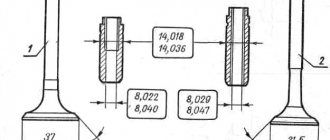
The valve consists of a rod (rod, neck) and a cap with a flat surface (plate, head) covering the combustion chamber. The rod moves along a sleeve that guides its movement. The entire timing belt is lubricated with engine oil. To prevent lubricant from entering the combustion chambers, oil seals are provided.
Each valve timing must strictly correspond to the position of the pistons in the cylinders. Therefore, the crankshaft and camshaft are rigidly connected through the drive, with the first shaft rotating exactly twice as fast as the second. The full operating cycle of the engine consists of four phases (cycles):
- Inlet. Moving down in the cylinder, the piston creates a vacuum above itself. At the same time, the intake valve opens and the fuel-air mixture (FA) enters the combustion chamber under low pressure. When the piston reaches bottom dead center (BDC), the intake valve begins to close. During this stroke, the crankshaft rotates 180°.
- Compression. Having reached BDC, the piston changes direction of movement. As it rises, it compresses the fuel assembly and creates high pressure in the cylinder (8.5–11 atm in gasoline engines and 15–16 atm in diesel engines). In this case, the inlet and outlet valves are closed. As a result, the piston reaches top dead center (TDC). In two strokes, the crankshaft made one revolution, that is, it rotated 360°.
- Working progress. A spark ignites the fuel assembly, and under the pressure of the resulting gas, the piston is directed to BDC. During this phase the valves are also closed. Since the beginning of the working cycle, the crankshaft has rotated 540°.
- Release. Having passed BDC, the piston begins to move upward, compressing the gaseous combustion products of the fuel assembly. At the same time, the exhaust valve opens, and under the pressure of the piston, gases are removed from the combustion chamber. In four strokes, the crankshaft made two revolutions (rotated 720°).
The gear ratio between the crankshaft and camshaft is 2:1. Therefore, during the operating cycle the camshaft makes one full revolution.
The timing belts of modern engines differ in the following parameters:
- upper or lower location of the camshaft;
- number of camshafts - one (SOHC) or two (DOHC) shafts;
- number of valves in one cylinder (from 2 to 5);
- type of drive from the crankshaft to the camshaft (toothed belt, chain or gear).
The first carburetor engine of VAZ models produced from 1970 to 1980 has four cylinders with a total volume of 1.2 liters and a power of 60 hp. With. and is a classic in-line four-stroke power unit. Its valve train consists of eight valves (two for each cylinder). Unpretentiousness and reliability in operation allows it to use AI-76 gasoline.
Video: operation of the gas distribution mechanism
Gas distribution mechanism VAZ 2101
The gas distribution mechanism of the VAZ 2101 is driven by the crankshaft, and the camshaft is responsible for the operation of the valves.
The torque from the engine crankshaft (1) through the drive sprocket (2), chain (3) and driven sprocket (6) is transmitted to the camshaft (7), located in the cylinder head (cylinder head). The camshaft lobes periodically act on the drive arms or rockers (8), driving the valves (9). Thermal clearances of the valves are set by adjusting bolts (11) located in the bushings (10). Reliable operation of the chain drive is ensured by the bushing (4) and the adjusting unit (5), the tensioner, and the damper (12).
The power strokes in the cylinders of the VAZ 2101 engine have a certain sequence.
Do-it-yourself valve adjustment on the “Classic”
To adjust the valves on a rear-wheel drive VAZ car with a carburetor engine, prepare the tool and open the hood. The work should be done on a cold engine, the size of the feeler gauge for adjustment is 0.15 mm. We perform the following sequential actions:
- put the gearbox in neutral;
- unscrew the 3 nuts of the upper air filter cover (10th key);
- dismantle the cover and filter element;
- unscrew the 4 nuts securing the air filter housing (key 8), remove the crankcase gas hose, and move the housing to the side;
- disconnect the choke cable from the carburetor and the accelerator rod from the valve cover;
- unscrew the six bolts securing the cover;
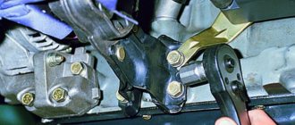
- Having gained access to the valves, we proceed to adjustment. We take a 38mm wrench (special for a ratchet), place it on the crankshaft pulley nut, turn the crankshaft until the marks on the crankshaft align;
- We insert a feeler gauge between the r/v cam and the rocker (rocker arm), and measure the gap. The probe should enter with a slight force (tension), if it does not go through, or the gap is very large, it is necessary to make an adjustment;
- in this position of the marks, valves No. 8 and No. 6 are adjusted, the counting is carried out from the engine radiator;
- the excess clearance is determined by hand moving up/down with the feeler gauge installed; if the TK is higher than normal, the rocker will “play.” If the gap is less than the specified one, you will not be able to insert the feeler gauge;
- to adjust with a 17 key, loosen the lower lock nut, and by changing the position of the nut under the 13 key, set the required gap;
- Having adjusted the valve with the dipstick installed, holding it with the 13th key, tighten the locknut. There is one small nuance here: usually when the locking nut is tightened, the gap decreases somewhat (“tightens”), so when adjusting, the feeler gauge between the rocker and the camshaft should move a little more freely. However, you can easily adapt to this; everything becomes clear as you work;
- turn the crankshaft 180 degrees, the camshaft mark should move 90º, in this position we make the cam number 7 and 4;
- We turn the crankshaft again, here the upper mark will no longer be visible, so we are guided by the lower mark, which is located on the c/shaft pulley;
- in this position we adjust valves 1 and 3;
- Let's turn the crankshaft 180º again (the mark on the camshaft will be shifted 90 degrees from the top position, but in the other direction), adjust the clearances. No. 5 and No. 2.
Having completed the ROK, close the valve cover, start the engine, and check the operation of the engine.
Preparatory work
Before starting the adjustment, you should perform the following operations:
- remove the air filter housing from the carburetor;
- remove the pipes and wires that prevent the dismantling of the timing cover;
- unscrew the nuts securing the timing cover;
- remove the timing cover.
When access to the valves is ensured, you can begin adjusting the thermal clearances. It should be remembered that the gap value of 0.15 mm was set by the designers for a cold engine. Therefore, before carrying out work, you must wait until the engine has cooled down. In addition, working on a hot engine can cause burns.
Adjusting the valves on a VAZ 2107 carburetor and on an injection model is absolutely no different. The only exceptions are engines on which hydraulic clearance compensators are installed. In this case, no adjustment is required.
Valve adjustment table
Not everyone can remember by heart the order in which the valve should be made, so for those who are “forgetful”, special adjustment tables are compiled, from which you can easily understand at what position of the crankshaft a particular valve needs to be adjusted.
There are also tables of the dependence of the recommended gap on the ambient temperature; they can also indicate values for the RK using an indicator.
If you look at the table, you can understand from it that the optimal value of 0.15 mm is valid at an ambient temperature of +20ºC. If you decide to adjust the valves outside in winter at zero degrees, then in this case you need to set the gap to 0.135 mm, and if at +30º - 0.158 mm.
Why adjustment is needed
When heated, engine parts, like any physical body, expand. This is especially true for elements of the gas distribution mechanism. The main timing parts - the valves - are in direct contact with the hot gases in the cylinder, opening and closing the intake and exhaust ports. The tightness of valve closure affects engine compression, efficiency and power.
The valves close under the influence of special springs, and to open they are pressed by rockers - levers driven by camshaft cams. When the rocker is not pressing on the valve stem, there should be a thermal gap between it and the camshaft. Why is valve clearance needed on VAZ 2107?
When the engine heats up, the length of the valve stems increases especially strongly (the larger the linear dimension, the greater the absolute value of thermal deformation). If in a cold state the parts fit tightly, when heated the rod will be constantly pressed, the valve will not close the window, which will lead to gas breakthrough. This threatens, in addition to reducing efficiency, burnout of the valve plates and engine breakdown. Therefore, there should be a gap of 0.15 mm between the rocker and the camshaft of a cold engine.
If the gap is greater than what is provided, the valves do not open well and the mechanism knocks; if it is less, the valves remain slightly open when this is unacceptable.
Over time, parts wear out and wear appears on the camshaft cams, rockers and valve stems. Therefore, owners of cars that are not equipped with hydraulic valve clearance compensators have to regularly check and adjust the timing belt clearances.
Setting valve clearances using an indicator
The procedure for adjusting the indicator when using the indicator generally does not differ from the sequence of actions when adjusting using a probe, but a different tool is used. To adjust the valve mechanism in this case, you will need a rack (bar) and the indicator itself; the device is sold as a set in specialized auto stores. If you really want to, you can make a bar for installing the indicator yourself; finding the necessary drawing on the Internet is not a problem.
When setting the gaps using an indicator, a more precise setting is obtained, since the feeler gauge is not able to catch all the irregularities of the camshaft cams and wear on the rockers. The procedure for the RK using a special device is as follows:
- just as when adjusting with a feeler gauge, set the gear to neutral, open the hood, remove the valve cover;
- we combine the camshaft marks to adjust the 8th and 6th valves;
- We attach the indicator strip to the studs on the left side of the camshaft bed;
- if we adjust the sixth valve, we fix the indicator on top of the corresponding (6th) rocker using a holder;
- Using a key or hand, we raise and lower the rocker, and note on the indicator how many divisions the arrow deviates.
Here it makes sense to refer to the table, which provides data on indicator settings, since when adjusting with a probe, TK is measured in millimeters, and with an indicator - in divisions. For example, for a standard value of 0.15 mm the indicator value is 52, which means that the arrow with the required gap deviates by fifty-two divisions. If the TK is greater than the norm, it needs to be reduced; let’s look at how this happens:
- Let’s say, instead of the required 52, the indicator showed the value 72 (“extra” 20 divisions);
- set the arrow to “zero”, loosen the lock nut, use a 13mm wrench to turn the adjusting bolt towards decreasing the gap, watch the indicator;
- when you turn the key, the indicator needle begins to deviate counterclockwise, it is necessary that it “passes” 20 divisions (since 72-52 = 20);
- Having achieved the desired reading on the dial gauge, holding it with a key of 13, use the “seventeenth” key to tighten the lock nut;
- Having adjusted both valves (8 and 6) in this way, turn the shaft and adjust the cl. No. 4 and 7, then we then repeat all the operations that were described earlier for a carburetor internal combustion engine.
After the adjustment, install the valve cover, start the engine, see how it works, listen for any extraneous sounds.
Valve mechanism malfunctions
A situation often arises when, even after adjustment, the valves continue to knock, and the knocking can be quite strong and unpleasant. The main reasons for extraneous noise in this case:
- worn camshaft cams;
- development on rockers;
- camshaft play in the bed (aluminum body);
- wear of pushers.
To determine the defective parts, it is necessary to remove the r/shaft and do a visual inspection. The wear of the camshaft bearings is determined using a micrometer; each of the bearing journals has its own specific size.
Adjustment of valve clearances on rear-wheel drive VAZ cars is usually carried out every 20-25 thousand kilometers, also when knocking occurs or there is a suspicion that the valves are “pinched”. If the gaps are less than normal, the engine runs unevenly, especially at idle, acceleration dynamics are lost, and dips appear.
You need to pay attention to the operation of the valves in the car if a characteristic knocking sound occurs during engine operation, with a noticeable drop in its power, an increase in fuel consumption, and also with unstable idling. Due to some design features of the car's gas distribution system, it needs servicing approximately every six months. For many motorists, adjusting the VAZ 2106 valves with their own hands has become a familiar procedure, even because this work is not particularly difficult.
Signs and consequences of improper clearance
Ideally, the precision of the valves ensures zero clearance. Then the valve will clearly follow the trajectory specified by the camshaft cam profile. It has a rather complex shape that is carefully selected by the motor developers.
But this can only be realized with the use of hydraulic gap compensators, which, depending on the specific design, are also called hydraulic pushers and hydraulic supports.
In other cases, the gap will be small, but quite finite, depending on temperature. ICE developers experimentally and by calculation determine what it should be like initially, so that in any conditions, changing the gaps does not affect the operation of the engine, causing damage to it or reducing its consumer qualities.
Big gap
At first glance, increasing valve clearances looks safe. No thermal changes will reduce them to zero, which is fraught with problems.
But the growth of such reserves does not pass without a trace:
- the engine begins to make a characteristic knock, which is associated with increased acceleration of parts before coming into contact;
- shock loads lead to increased wear and chipping of metal surfaces, the resulting dust and chips disperse throughout the engine, damaging all parts that are lubricated from a common crankcase;
- The valve timing begins to lag due to the time required to select the gaps, which leads to deterioration in performance at high speeds.
It is interesting that a loudly knocking engine with huge gaps can pull perfectly at low speeds, acquiring, as they say, “tractor traction.” But you cannot do this deliberately; the motor will quickly be worn out by products from surfaces subject to shock loads.
Small gap
Reducing the gap is fraught with much faster and irreparable consequences. As it warms up, the insufficient clearance will quickly become zero, and interference will appear in the joint of the cams and valves. As a result, the valve discs will no longer fit tightly into their seats.
The cooling of the valve plates will be disrupted; according to calculations, they dump some of the heat into the metal of the head during the closing phase. Even though the valves are made from heat-resistant steels, they will quickly overheat and burn out using the high temperature and available oxygen. The motor will lose compression and fail.
Why do you need valve adjustment?
If you carefully examine the valve system of the “six”, its design can be roughly compared to a rocker arm diagram. Rotating, the camshaft presses its cam on one side of the rocker arm, lifts it, while the second edge, located on the top of the valve, lowers the rocker arm, thereby opening paths for injection of the fuel mixture or for removing gases.
It is necessary to provide a certain gap between the parts in question. The valve opens to an extent that ensures the correct functioning of the motor.
If the gap is too small, the valves do not close completely, which causes a decrease in engine power, entails excessive fuel consumption and failure of the valves themselves. In addition, due to the discrepancy between the clearances and the standard indicators, engine noise increases, the rods are deformed, and accordingly, the under-closing gap of the valve itself increases even more.
The procedure for adjusting the valves of the VAZ 2106
1. At the very beginning, the gas distribution mechanism is disassembled - these actions will open access to setting up and adjusting the parts. For this purpose, the air filter is removed.
2. The next step is to remove the valve covers, which will allow you to see the camshaft housing and other internal parts.
3. The crankshaft is rotated so that the marks on the pulley and the front oil seal cover match. When the shaft is in this position, the compression stroke begins in the fourth cylinder.
4. The gap is checked: for this, a 0.15 mm feeler gauge is used, the insertion of which must be accompanied by a certain force. Gap adjustment is required if the feeler gauge passes into the gap too easily, or if it does not pass at all.
5. Use a wrench “14” to hold the adjusting bolt, and use a wrench “17” to loosen the lock nut. By turning the bolt, the required clearance is established, the bolt is secured with a lock nut. After performing these steps, a control measurement is carried out with a probe.
To adjust the valves as correctly as possible, you need to follow a certain procedure:
- Valves No. 6 and No. 8 are adjusted, the crankshaft is turned half a turn;
- A similar operation is carried out with valves No. 4 and No. 7, rotate the shaft;
- Valves No. 1 and No. 3, shaft rotation;
- Finally, the clearance of valves No. 5 and No. 2 is set.
After these steps, several full turns of the shaft are performed, a control check of the gaps is made with a feeler gauge, and all previously removed parts are assembled.
In fact, we were able to verify that adjustment with a feeler gauge is not particularly difficult; in fact, the shaft is turned and the bolts are adjusted. But this method is frankly inaccurate due to the existing wear at the points of contact between the cam and the rocker arm.
The above disadvantage does not exist if the gap adjustment is carried out using an indicator and an adjusting rod.
Puller drawings. Repair equipment. Tool
Device for tensioning the timing belt (for a new type of roller).
The device is a metal, slightly curved strip, 2 - 3 mm thick, 120 mm long. and width - 25 mm. On one side at a distance of 10 mm. two pins with a diameter of 4 mm are installed from the end. The height of the pins is 10 mm, the distance between the pins is 17 mm. The diameter of the semicircle is 16 mm. Everything should be clear from the photograph of the device.
Instead of this device, to tension the timing belt, you can use two drills (4 mm in diameter) inserted into the holes of the tension roller. We insert a screwdriver between the drills and use it as a lever to tighten the timing belt.
Device for adjusting valves.
Due to the relative complexity of this device and its low cost (less than 200 rubles), I recommend just buying it.
As a last resort, you can use a pair of regular flathead screwdrivers. Using one powerful screwdriver, we recess the pusher, and with the second (you can bend it a little and sharpen it in place) we fix the pusher by the side. But this method is extremely inconvenient and the fixing screwdriver can fly out; in general, it’s only suitable as a last resort.
Adjusting valve clearances using an adjusting rack
1. As in the case described above, the car must be placed on a level surface. This second adjustment method will allow you to achieve greater accuracy when performing work. The same tools are used and the same steps are followed to remove the filter.
2. After aligning the marks of the pulley and the oil seal cover, install the rack, which is attached to the camshaft housing with three bolts.
3. Next, a dial indicator is installed in the slot on the rail, its scale is set to zero.
4. The existing gap is measured and, if necessary, adjusted in a similar way to the feeler gauge adjustment method. The adjustment is carried out according to the scheme discussed in the first case.
As a result, properly adjusted valves will reduce fuel consumption, increase engine power, stabilize its operation and reduce noise generation.
Below you can watch a video on how to independently adjust the valves on a VAZ-2106.
The need to adjust the valves in VAZ-2106 cars arises as the gas distribution mechanism consumes a certain resource. Constant exposure to high temperatures leads to the loss of its elements of their original properties. As a result, the gaps between the camshaft cams and the pressure levers increase.
Valve lid
The valve cover covers and seals the timing belt, preventing grease from camshaft, valves and other parts from leaking out. In addition, new engine oil is poured through its neck when replacing. Therefore, a sealing gasket is installed between the valve cover and the cylinder head, which is changed every time after repair or adjustment of the valves.
Before replacing it, you should thoroughly wipe the surfaces of the cylinder head and cover to remove any remaining engine oil. Then the gasket is put on the cylinder head studs and pressed with the lid. It is necessary that the gasket fits exactly into the grooves of the cover. After this, the fastening nuts are tightened in a strictly defined sequence.
When is it necessary to adjust valves?
The normal gaps between the cams and levers provided for by the design of the VAZ-2106 engine are 0.15 mm, and reducing or increasing them will entail a number of consequences. Although their non-compliance with the established requirements does not pose an emergency hazard to the entire engine, it causes rapid wear of parts, engine overheating, a decrease in its power, and increased fuel consumption.
Typically, valve thermal clearances are adjusted every 20-30,000 km, as well as after any repair work related to the gas distribution mechanism. In addition, such a need may arise due to malfunction of other engine systems or mechanisms.
The main sign that it is time to adjust the valves is a characteristic knocking sound coming from under the valve cover. It can also be clearly heard from inside the car when the hood is closed. It is important here not to confuse this sound with the clatter of piston pins, which can occur during detonation. Valves, unlike fingers, “knock” both at idle and under load. The latter, in the event of detonation, reveal themselves only under load.
Main malfunctions of the VAZ 2101 timing belt
According to statistics, every fifth engine malfunction occurs in the gas distribution mechanism. Sometimes different faults have similar symptoms, so a lot of time is spent on diagnosis and repair. The following are the most common causes of timing belt failure.
- Incorrectly set thermal gap between rockers (levers, rocker arms) and camshaft cams. This results in incomplete opening or closing of the valves. During operation, the valve mechanism heats up, the metal expands, and the valve stems elongate. If the thermal gap is set incorrectly, the engine will have difficulty starting and will begin to lose power, popping noises will appear from the muffler and a knocking noise will appear in the engine area. This malfunction is eliminated by adjusting the gap or replacing the valves and camshaft if they are worn.
- Worn valve stem seals, valve stems or guide bushings. The consequence of this will be an increase in engine oil consumption and the appearance of smoke from the exhaust pipe during idling or acceleration. The malfunction is eliminated by replacing the caps, valves and repairing the cylinder head.
- Failure of the camshaft drive as a result of a weakened or broken chain, breakdown of the tensioner or chain guide, wear of the sprockets. As a result, the valve timing will be disrupted, the valves will freeze, and the engine will stall. It will require a major overhaul with the replacement of all failed parts.
Valve valves may become bent as a result of slipping or broken timing chain. - Broken or tired valve springs. The valves will not close completely and will begin to knock, and the valve timing will be disrupted. In this case, the springs should be replaced.
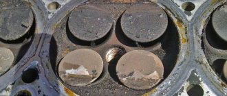
- Incomplete closure of valves due to burning of the working chamfers of the valve plates, the formation of deposits from low-quality engine oil and fuel. The consequences will be similar to those described in point 1 - repair and replacement of the valves will be required.
- Wear of bearings and camshaft cams. As a result, the valve timing will be disrupted, the power and throttle response of the engine will decrease, a knock will appear in the timing belt, and it will become impossible to adjust the thermal clearance of the valves. The problem is solved by replacing worn elements.
After eliminating any of the malfunctions of the VAZ 2101 engine, it will be necessary to adjust the gap between the rockers and the camshaft cams.
Video: the influence of thermal valve clearance on timing belt operation
Preparation stage
Adjusting the valves of the VAZ-2106 is not particularly difficult and does not require the use of special tools. Here you will need:
- a set of wrenches (heads) for 10, 13 and 17;
- key (head) 36 for cranking the crankshaft;
- Screwdriver Set;
- a measuring probe with a thickness of 0.15 mm (included in the tool kit for the car from the factory, can be purchased at any auto store or a special strip with an indicator);
- new valve cover gasket;
- automotive sealant;
- assistant (for greater convenience when setting valve timing).
The car must be placed in a viewing hole, secured with the parking brake, and the engine must be allowed to cool completely. After this, open the hood and remove the air filter: it will interfere with the removal of the valve cover.
Dismantling and repair of the cylinder head of the VAZ 2101
To replace valve mechanisms and guide bushings, you will need to dismantle the cylinder head. This operation is quite labor-intensive and painstaking, requiring certain metalworking skills. To perform this you will need the following tools:
- a set of wrenches (heads 8, 10, 13, 17, 19 are required);
- slotted and Phillips screwdrivers;
- pliers;
- mandrels for pressing out and pressing in guide bushings;
- device A.60311/R for removing valve springs (depressurizer);
- puller and mandrel for oil seals;
- torque wrench.
Before dismantling the cylinder head, you must:
- Drain antifreeze from the engine cooling system.
- Remove the air filter and carburetor, first disconnecting all pipes and hoses.
- Disconnect the wires, unscrew the spark plugs and antifreeze temperature sensor.
- After unscrewing the fastening nuts with a size 10 wrench, remove the valve cover along with the old gasket.
Replacing valve springs and oil seals
Support bearings, camshaft, springs and oil seals can be replaced without removing the cylinder head. To do this, you will need a device for extracting (loosening) the valve springs. First, the specified elements are replaced on the valves of the first and fourth cylinders, which are at TDC. Then the crankshaft is turned by a crooked starter 180°, and the operation is repeated for the valves of the second and third cylinders. All actions are performed in a strictly defined sequence.
- A soft metal rod with a diameter of about 8 mm is inserted into the spark plug hole between the piston and the valve. You can use tin solder, copper, bronze, brass, or, in extreme cases, a Phillips screwdriver.
If no other repair work is required, the timing belt is assembled in the reverse order. After this, it is necessary to adjust the thermal clearance of the valves.
Replacement and grinding of valves, installation of new guide bushings
If the valve caps are burnt out, or a coating of impurities in oil and fuel has formed on them, preventing a tight fit to the seats, the valves must be replaced. This will require dismantling the cylinder head, that is, you will need to complete all the points of the above algorithm before installing new oil seals on the valve necks. The caps and springs themselves can be installed on the removed cylinder head after replacing and grinding in the valves. The work is performed in the following order.
- The hoses are disconnected from the carburetor, the inlet pipe and the outlet pipe of the cylinder head cooling jacket.
- The starter protective shield and the exhaust pipe of the mufflers are disconnected from the exhaust manifold.
- The oil pressure sensor is disconnected.
- The bolts securing the cylinder head to the cylinder block are broken off and then unscrewed with a wrench and ratchet. The cylinder head is removed.
- If the valve mechanisms have not been disassembled, they are removed in accordance with the instructions given above (see “Replacing valve springs and valve stem seals”).
Video: repair of cylinder head VAZ 2101–07
Adjustment using a feeler gauge
1.Using a 10mm wrench (socket), unscrew the eight bolts securing the valve covers. Disconnect the crankcase ventilation hoses from it. Carefully remove it and set it aside.
2. Before proceeding with the adjustment, you need to check the tension of the timing chain. If she's okay, we move on.
3. Set the piston of the fourth cylinder to the position of its top dead center. To do this, you will need to turn off the gear, go down into the pit, remove the engine mudguard, then use a “36” wrench or a similar head placed on the crankshaft pulley mounting nut to turn it until the marks on the camshaft sprocket and its bearing housing coincide . The same procedure can be carried out by jacking up and turning one of the rear wheels with 4th gear engaged, or by slowly pushing the car (if there is no inspection hole).
4. When the marks coincide, valves 6 and 8 (counted from the front of the engine from left to right) should be completely closed, and their clearances between the cams and levers should be maximum.
5.Insert the dipstick into gap 6 of the valve. It should enter there with noticeable resistance. If the gap is greater than the thickness of the feeler gauge, or the feeler gauge cannot be pushed into the gap, adjustment is required.
6.To do this, take a 17mm wrench, place it on the locknut, and use another 13mm wrench to loosen or tighten the adjusting screw, achieving the desired amount of clearance. It should be noted here that as the locknut is tightened, it may change the gap, so measurements will need to be repeated after tightening it.
7.In the same way we adjust the gap on the 8th valve.
8.After this, it is necessary to turn the crankshaft exactly 180 0 in the manner described above, and adjust the 4th and 7th valves.
9. Next, rotate the crankshaft 360 0 and adjust the clearances of valves 1 and 3.
10.The next stage is to turn the crankshaft by 540 0 with adjustment of 5 and 2 valves.
Below is a table indicating the crankshaft rotation angle and the procedure for adjusting the thermal valve clearances.
| Crank angle | 0 0 | 180 0 | 360 0 | 540 0 |
| Camshaft angle | 0 0 | 90 0 | 180 0 | 270 0 |
| Cylinder number | 4,3 | 2,4 | 1,2 | 3,1 |
| Adjustable valve number | 6,8 | 4,7 | 1,3 | 5,2 |
Operating principle of internal combustion engine timing valves
An ordinary ordinary driver, when it is necessary to adjust the valves, does not do it himself, but goes to a car service center.
Because this requires certain skills and time. To teach yourself how to adjust valve clearances, you need to know the principle of their operation. An internal combustion engine has two shafts: the crankshaft (crankshaft) and the camshaft (camshaft). They are connected to each other through pulleys and a belt, through sprockets and a chain. The most common option is a timing belt driven engine. The crankshaft to camshaft transmission ratio is 2:1 (two to one).
The cams have a special irregular smooth shape that closes and opens the valves so that they correspond to the position of the crankshaft and camshaft, the engine stroke and valve timing.
When the internal combustion engine is running, it heats up accordingly, its parts heat up and expand due to high temperature. Because of this, the distance between the camshaft and the valve tappet changes slightly.
Question: why does the engine run differently when cold and when hot? Answer: because when the engine warms up to operating temperature, the valve tappet is pressed tightly against the valve and camshaft. This ensures efficient operation of the internal combustion engine.
And, if the valve end stops above the pusher, then a gap appears between the seat and the plate, and this leads to a decrease in compression in the cylinder.
It’s easy to check the compression: turn off the engine, unscrew the spark plug, screw in a special pressure gauge instead, turn the ignition key, get out and see what pressure the pressure gauge of a given cylinder shows.
And, if the end of a closed valve is located below the pusher, then during a certain valve timing phase, the valve will not open to the full distance it should. And this leads to a loss of power due to the slow removal of exhaust gases.
Adjusting valves using a gauge indicator (rack)
Most car owners adjust the valves using the method described above. But there is another method that provides the most accurate determination of the thermal gap. Here its measurement is carried out using a special rod and an indicator (dial micrometer). The adjustment itself occurs in the same way, i.e. by tightening and unscrewing the valve adjusting screws in the same sequence as turning the crankshaft.
The only thing you need is the reading table that comes with the device. With its help, you can find out what the gap should be (in the indicator readings) at a certain air temperature.
Measurements of the size of the gaps are carried out as follows.
1. We attach the rack to the camshaft bed and screw it on.
2. We fix the indicator in the holder and fix it on the rack above the rocker (rocker arm) of the valve that we plan to regulate. It must be fixed so that its rod rests on the very tip of the rocker platform.
3. Having determined the air temperature, look at the table and find out how many divisions the indicator needle should deviate under such conditions. At 20 0 C, this is 52 divisions, which are equal to the same 0.15 mm.
4. Having set the arrow of the device to “0”, raise and lower the rocker arm and see how much the arrow deviates. If this value is greater than 52, for example, 70, turn the indicator dial counterclockwise by 18 divisions.
5.Next, as in the previous case, use the adjusting screw to adjust the gap until the arrow coincides with zero when the rocker arm is raised.
6. If after tightening the locknut there is an error of 2-3 divisions, this is not a problem, but it is better that it is oriented towards the increase.