03/04/2022 1,835 Security system
Author: Ivan Baranov
The CAN bus is an interface used to make vehicle control more simplified. This is ensured through the exchange of data between different systems; the information is transferred in encrypted form.
[Hide]
Where is the CAN bus located?
The CAN module in a car is a network of sensors and controllers that are designed to combine all control devices into one system.
This automotive technology is used as a socket with which the following control units can be connected:
- “signals” - an automatic engine start module can be connected to the anti-theft system;
- anti-lock braking system "ABS";
- safety mechanisms, in particular airbags and their sensors;
- vehicle powertrain control systems;
- instrument cluster;
- cruise control systems;
- air conditioner and heating unit;
- automatic transmission control systems, etc.
A CAN module is a device whose installation location may differ from the vehicle manufacturer.
If it is unknown where the interface is located, this point is clarified in the service documentation for the car; it is usually installed:
- under the hood of a car;
- inside the vehicle;
- under the control combination.
Purpose and functions of the canbus
If you correctly install and connect wires to the interface, you can provide the following options:
- reducing the impact of external interference on the functioning of main and additional mechanisms and components;
- the ability to connect and configure any electronic devices, including security systems;
- a simple principle of connecting and operating additional electronic devices and instruments that are available in the car;
- faster procedure for transferring information to certain equipment and vehicle mechanisms;
- the ability to send and receive digital data simultaneously, as well as analyze information;
- quick setup and connection of the remote engine start option.
Channel “Crossover 159” spoke in more detail about the purpose and general characteristics of the CAN module.
Malfunctions
Tire failures usually come down to several typical cases:
- power failure of individual devices;
- damage to wiring and connectors;
- controller failure.
The basis of all network peripherals is modern microelectronics and large mass-produced integrated controllers, so the reliability of the equipment as a whole is quite high. But the search for a problematic unit can sometimes take a long time due to their parallel connection and placement throughout the car.
Design and principle of operation
By design, this interface is made in the form of a module in a plastic case or a block for connecting conductors. The digital bus includes several CAN cables. This device is connected to the on-board network via a single conductor.
The bus works on the principle of sending data in encrypted form. Each transmitted message has a special unique identifier. There may be information: “the speed of the car is 50 km/h,” “the coolant temperature is 90 degrees Celsius,” etc. When sending messages, all electronic units receive data that is verified by identifiers. If the information is relevant to a specific module, then it is processed, if not, it is ignored.
Depending on the model, the length of the interface identifier can be 11 or 29 bits.
Each device reads information transmitted to the bus. The lower priority transmitter must release the bus because the dominant level distorts its transmission. If the priority of the transmitted packets is higher, then it is not touched. A device that loses connection while sending messages will automatically restore it after a certain time interval.
The CAN bus can operate in several modes:
- Standalone, background or sleeping. When this mode is turned on, all main units and components are turned off and the engine is not started. The bus is still supplied with voltage from the on-board network. Its value is small, which makes it possible to prevent the battery from discharging.
- Wake up or start the interface. In this mode, the device starts working, this happens when the ignition system is turned on. If the vehicle is equipped with a Start/Stop button, the CAN bus starts working when it is pressed. The voltage stabilization function is turned on, as a result of which power begins to flow to the controllers and sensors.
- Turning on the active mode leads to the beginning of the process of information exchange between actuators and regulators. The voltage in the network increases, since the bus can consume up to 85 mA of current.
- Shutdown or sleep mode. When the car engine is stopped, all units and mechanisms connected via the CAN interface are turned off. The power supply to them stops.
User Valentin Belyaev spoke in detail about the operating principle of the digital interface.
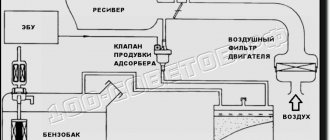
How information is transmitted
So, the CAN bus is a network through which information is exchanged between devices. Let's take the engine control unit as an example - it has not only the main microcontroller, but also a CAN device that generates and sends pulses along the H (CAN-high) and L (CAN-low) buses, which are called twisted pair.
Each unit connected to the CAN bus has a certain input resistance, resulting in a total CAN bus load.
The total load resistance depends on the number of electronic control units and actuators connected to the bus.
Rice. 2. Fragment of a CAN bus with load distribution in the wires: CAN High CAN Low
Car systems and control units have not only different load resistances, but also data transfer rates, all of which can interfere with the processing of different types of signals. To solve this technical problem, a converter is used for communication between buses. Such a converter is usually called a gateway; this device is most often found in a car everything is built into the design of the control unit, instrument cluster, and can also be designed as a separate unit.
Rice. 3. Gateway block diagram
Signs and causes
Advantages and disadvantages
If the car is equipped with a digital interface, this provides the following advantages:
- Easy to install an alarm on a vehicle. The presence of a CAN bus in a car allows for a faster and simplified algorithm for connecting the security system.
- High speed of sending information between units and systems, which ensures the speed of nodes.
- Good immunity to interference.
- All digital interfaces have a multi-level control system. Thanks to this, you can prevent errors when sending and receiving information.
- The digital interface, working in active mode, performs speed spread across various channels independently. Thanks to this, all systems operate as quickly as possible.
- CAN bus security. If an attempt is made to gain unauthorized access to the vehicle, the system may block components and assemblies.
Minuses:
- Some systems have limitations on the amount of information transmitted. If the car is relatively new and equipped with different electronic devices, this leads to an increase in the load on the data transmission channel. As a result, response time increases.
- Most information transmitted over a digital interface has a specific purpose. The system allocates a small portion of traffic for useful data.
- There may be a problem of lack of standardization. This often happens when using higher-level protocols.
System functionality
To understand what a CAN bus is, you need to understand its functional purpose.
It is designed to transmit real-time frames that contain information about a value (for example, a change in speed) or the occurrence of an event from one transmitter node to program receivers.
The command consists of 3 sections: name, event value, time of observation of the variable.
Key importance is attached to the indicator variable. If the message does not contain time information, then this message is accepted by the system upon receipt.
When a communication system computer requests a parameter status indicator, it is sent in priority order.
Varieties and labeling
Based on the type of identifier, such devices are divided into two types:
- CAN2, 0A. This is a marking of interfaces that can operate in an 11-bit information transfer format. This type of device is not able to detect pulse errors from blocks that operate with 29 bits.
- CAN2, 0B. This is a marking for buses operating in 11-bit format. The main feature is the ability to transfer information to control units when a 29-bit identifier is detected.
Depending on the area of application, tires are divided into three classes:
- For a vehicle engine. When connecting a bus, the maximum speed of data transfer and communication between control devices is ensured. Information is sent via an additional channel. The main purpose is to synchronize the operation of the microprocessor module with other systems. For example, anti-lock wheel assembly, transmission, etc.
- Comfort class digital interfaces. This class of buses is designed to interact with any device of this type. The interface is used to work with systems for electronically changing the position of electric mirrors, seat heating, sunroof control, etc.
- Information and command devices. They are characterized by similar speed when sending data. Such buses are usually used for communication between systems that are required to service the vehicle.
The Diyordie channel talked about the purpose of the digital interface, as well as its varieties in a car.
Do-it-yourself alarm connection
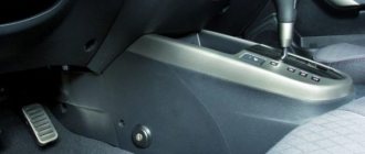
To connect the security system to the digital interface, you need to know the installation location of the microprocessor alarm control module. This device is installed under the instrument cluster of the car. The unit can be installed behind a glove box or audio system.
Necessary devices and tools
You must first prepare:
- voltage tester - multimeter;
- knife;
- electrical tape;
- Phillips head screwdriver.
Step-by-step instruction
Installation is done like this:
- When starting the task, you need to make sure that the anti-theft system is working. If the installation of the system has not been completed, you need to connect all devices to the control unit, and it to the battery.
- A search is made for the main cable that goes to the digital interface. This wire is always thick and usually has an orange sheath.
- The microprocessor module of the anti-theft system must be connected to this conductor. To carry out the task, a digital bus block is used.
- If the security system control unit has not been installed, it must be installed. It should be placed in a hidden place, not exposed to moisture. During installation, the module is securely fixed using plastic ties or self-tapping screws.
- All wire connections must be insulated using heat-shrinkable tubing or electrical tape. After connection, the performed actions are diagnosed. If problems arise, you need to use a multimeter to find the damaged area.
- At the last stage, it is necessary to check and configure all data transmission channels. If there are additional channels, they are also configured.
The “Garage Amateur” channel spoke in detail about the installation and connection of the Starline anti-theft system with a CAN bus.
Difficulties in installing security kits
Installing any such system is a major intervention in the vehicle's functions. The correctness of this event very often depends on the level of knowledge of the specialist who will install this equipment. The reliability (as well as the correctness) of such a thing will then affect the operation of the vehicle itself. Otherwise, this can lead to unpleasant moments, such as when the engine simply stalls on a winter road in the steppe.
However, with the Can module such problems will not arise. It is easy to highlight its main advantages:
- no interference with the internal structure of the car;
- coordination of any security device with the digital standard wiring of the car;
- eliminating the appearance of errors on the on-board computer;
- Availability of installation on any car.
Modern alarm systems have a CAN driver and support for the protocols themselves, such as CAN cars, which is an ideal option for a security system.
Can-crocodile
Working with the terminal
Before operation, you must take into account the recommendations for use, which are indicated in the service manual. The device is pre-configured.
Setting options
If you are using a terminal, there are two options to configure the interface:
- Using a special “Configurator” program for your computer. When starting the utility, go to the “Settings” tab and select the CAN item. In the window that opens, the necessary parameters are indicated.
- Using the "CanRegime" commands. Typically this option is used for remote configuration using SMS messages. Commands that are sent from monitoring software may be used.
More details about the commands that are specified after CanRegime:
- Mode—defines the operating mode. If the number is 0, then the digital interface is disabled, if 1, the standard filter is used. Numbers 2 and 3 indicate that the packets belong to the 29- or 11-bit class.
- BaudRate. The command is intended to determine the speed of the digital interface. It is important that this parameter matches the speed of information transfer in the car.
- TimeOut - Defines the timeout for each message. If the received value is too low, then the digital interface will not be able to catch all transmitted messages.
High level protocols
CAN just solves the problem of delivering information from one point to another, in small packets (only 8 bytes). Many aspects of data exchange remain beyond his competence. Due to the great demand in the market, the development of improved protocols - the so-called high-level protocols - immediately appeared. They undertook to provide a more expanded package of services. They are used when needed:
- Set launch standards, incl. exchange speed;
- Distribution of previously recognized addresses of interacting elements and types of messages;
- Accurate message markup;
- The order of error analysis.
Operating modes
There are several operating modes of the terminal:
- FMS - in it the car owner can find out the total fuel consumption, revolutions, vehicle mileage, axle load, and temperature of the power unit. It is possible to obtain data on the volume of fuel in the tank. To work in this mode, enter the filter type selection menu of the Configurator program. Specify the type of FMS mode and the speed of the digital interface, after which the “Apply” button is pressed.
- Listening mode is used to receive messages transmitted via a digital interface. To work with it, you need to go to the CAN bus settings in the program and select one of the operating parameters. This could be interface speed or latency; the type of filter does not matter in this case. After specifying the parameters, the “Listen” button is clicked.
- Custom filters are used to link information obtained by listening to the digital interface. After listening to the data, you need to select the type of filtering technology (for 11 or 29 bits). Data decryption is carried out in accordance with technical documentation.
- OBD2 test mode is used to scan the sending speed of information as well as the ID class. To launch this function, the car owner needs to connect directly to the digital interface or diagnostic connector. The mode is enabled by entering the “Settings” menu and selecting the “OBD2 Test” option. As a result, the terminal will begin sending requests with specific identifiers at various interface speeds. In the “Device” tab you can view the extracted and decrypted information.
Is it possible to make an analyzer with your own hands?
To perform this task, the car owner must have professional skills in the field of electronics:
- The device is assembled according to the diagram presented in the first photo in the gallery. You must first purchase all the parts necessary for manufacturing. The main component is the STM32F103С8Т6 board, equipped with a controller. You will also need an electrical circuit for the stabilizer and a CAN transceiver. You can use the MCP2551 device or another analogue.
- If you want to make the analyzer more technologically advanced, you can add a Bluetooth module to it. Thanks to this, the car owner can save important information to the smartphone’s memory.
- To program the analyzer, use any suitable software. According to reviews, the best option is Arduino or CANHacker utilities. The second utility has more options and has a function for filtering information.
- To flash the firmware, you will need a USB-TTL converter. This device is required for debugging; if it is missing, you can use ST-Link.
- After downloading the utility to the computer, the main file with the EXE extension is flashed into the block using a programmer. If the procedure is completed successfully, then you need to additionally install a jumper on the Bootloader. The assembled device must be synchronized with the computer using a USB cable.
- The next step is to add firmware to the analyzer. To complete the task you will need the MPHIDFlash utility.
- After successfully updating the program, the cable from the computer is disconnected and the jumper is removed. Drivers are being installed. If the assembly is completed correctly, then when connected to a PC, the analyzer will be detected as a COM port.
Photo gallery
Photos of circuits for making an analyzer yourself are given in this section.
General diagram for assembling an analyzing device
Board used as base
Project diagram
The project diagram for communication between two Arduino boards using CAN protocol and MCP2515 modules is shown in the following figure.
Connections on the transmitting side:
| Component - Contact | Arduino Nano |
| MPC2515 - VCC | +5V |
| MPC2515 - GND | GND |
| MPC2515 - CS | D10 (SPI_SS) |
| MPC2515 - SO | D12 (SPI_MISO) |
| MPC2515 - SI | D11 (SPI_MOSI) |
| MPC2515 - SCK | D13 (SPI_SCK) |
| MPC2515 - INT | D2 |
| DHT11 - VCC | +5V |
| DHT11 - GND | GND |
| DHT11 - OUT | A0 |
Receiver side connections:
| Component - Contact | Arduino Uno |
| MPC2515 - VCC | +5V |
| MPC2515 - GND | GND |
| MPC2515 - CS | 10 (SPI_SS) |
| MPC2515 - SO | 12 (SPI_MISO) |
| MPC2515 - SI | 11 (SPI_MOSI) |
| MPC2515 - SCK | 13 (SPI_SCK) |
| MPC2515 - INT | 2 |
| LCD (LCD display) - VSS | GND |
| LCD - VDD | +5V |
| LCD - V0 | to the middle contact of the potentiometer 10 kOhm |
| LCD - RS | 3 |
| LCD - RW | GND |
| LCD - E | 4 |
| LCD - D4 | 5 |
| LCD - D5 | 6 |
| LCD - D6 | 7 |
| LCD - D7 | 8 |
| LCD - A | +5V |
| LCD - K | GND |
Connections between two MCP2515 CAN modules:
H – CAN High L – CAN Low
| MCP2515 (Arduino Nano) | MCP2515 (Arduino UNO) |
| H | H |
| L | L |
After assembling the entire circuit on breadboards, we got the following design.