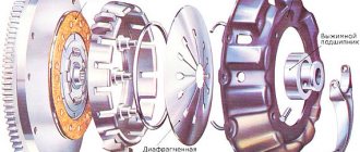
Any mechanism must have impact organs, as well as controls. The car clutch is no exception in this regard. Designed for short-term separation of the transmission and engine, it is an integral part of any vehicle and serves to ensure the ability to control the machine.
To transfer the impact from the driver to this mechanism, a hydraulic drive is usually used in passenger cars; One of the critical parts of such a device is the clutch master cylinder.
About the hydraulic drive device
To better understand what will be discussed, it is necessary to at least schematically imagine the design of such a drive. Let’s leave its purpose, structure, and role in the vehicle aside; in this case, the hydraulic drive itself is important.
Its implementation, as an example, as one of the possible options, can be seen in the figure below. This is enough to understand the structure and operation of the clutch drive, as well as to understand its role and significance in the vehicle.
Of the drive parts in the figure, it is necessary to note the following components:
- reservoir for filling brake fluid (1), which is used as a filler for the hydraulic drive;
- clutch master cylinder (2);
- hydraulic pipes (3,4,5) and hose (7);
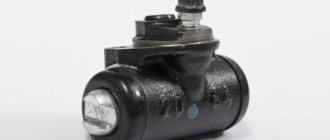
- clutch slave cylinder (8);
- pedal (6) and return spring (9).
Mechanical drive device
As already mentioned, the mechanical drive has an extremely simple structure and consists of the following structural elements:
- clutch pedal;
- cable;
- regulation device;
- lever drive;
- release bearing.
The main element of the mechanical drive is a flexible cable enclosed in a sheath. The drive pedal is located inside the car and is connected to the lever device (clutch fork) through a flexible cable. At the connection of the clutch cable and fork there is an adjusting device designed to set the free play of the pedal. The operation of a mechanical drive is extremely simple: the driver, by acting on the pedal, sets in motion a lever device, which in turn moves the release bearing along the guide, thereby disengaging the clutch.
How does a hydraulic drive work?
Without touching on the design of individual components of this mechanism, we can return to this a little later; it is enough to familiarize ourselves with its operation in a simplified manner. We will assume that the required amount of brake fluid is filled into the drive, it is in good working order and fully operational.
When you press the pedal (6), the force is transmitted through the rod to the clutch master cylinder (2). He perceives this force, and then transmits it through a system of tubes and hoses to the clutch slave cylinder. The latter, through the clutch fork and release bearing, disconnects the transmission from the engine.
Hydraulic clutch release drive
The vehicle uses a hydraulic clutch release drive with a suspended pedal structure (the pedal's swing axis is located above its platform). This type of drive is becoming increasingly common in modern passenger cars. Its advantages compared to a mechanical drive boil down mainly to the following:
- The clutch engages more smoothly, which reduces dynamic loads in the transmission, especially when starting the car, and increases ride comfort.
- The sealing of the passenger compartment of the body from the penetration of dust, dirt and moisture into it is significantly improved, since (with the brake pedal also of a “suspended” design) there are no hatches in the inclined floor of the body for the passage of the clutch and brake pedal levers.
- The master cylinders of the hydraulic clutch and foot brake actuators, located quite high on the body, and the elements of the mechanical part of the drives, are not covered in dirt and are well protected from dust, which facilitates the maintenance of these units and increases their durability.
- There are no lubrication points in the clutch drive, making vehicle maintenance easier.
- Significant layout possibilities emerge, since the “outboard” clutch and brake pedals, together with their master cylinders, can be placed on the front panel of the body in accordance with the specific layout of the vehicle.
How does the hydraulic drive work?
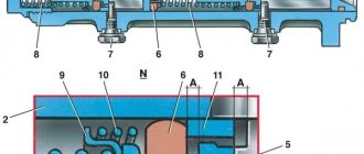
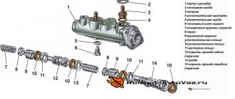
The design of the clutch master cylinder can be structurally designed in different ways, but in general the principle of operation is the same in all variants. As an example, the figure below shows a sectional view of the clutch master cylinder.
Among the main details are
- (2) - a pusher connecting the mechanism to the pedal;
- (3) master cylinder;
- (4) piston;
- plugs and return spring.
The figure shows that the clutch cylinder is divided into two parts by a partition. The upper half serves to fill the hydraulic drive with fluid entering the cylinder from the tank (5) and store its required working reserve. If everything is configured and adjusted correctly, then its level should be three quarters of the working volume.
The lower part serves as a working area. In the initial state, the piston (4) is pressed against the dividing wall by a spring, a gap A is formed between the pusher and the piston, and through it the liquid fills the working area.
When you press the pedal, the pusher, moving, closes gap A, the flow from the upper part to the lower part stops, the piston begins to move, transmitting force from the driver’s foot through a system of tubes and hoses to the working cylinder.
Due to the difference in the diameters of the piston and the outlet hole, its value increases, this becomes sufficient for the clutch to operate. This drive design makes it possible to lightly press the pedal to provide the required force to operate the entire mechanism.
When the pedal is released, the piston, under the influence of the spring and the pressure existing in the system, returns to its original position, and the pusher moves there, thereby restoring free penetration of liquid between the two parts of the cylinder.
Design and principle of operation of the electronic clutch drive
Recently, many companies have been offering completely new designs of clutch drives, which are used in advanced cars, including hybrid and electric ones. The “Electronic Clutch System” drive from Bosch deserves special attention.
Electronic Clutch System (literally “Electronic Clutch System”) is a system that allows you to implement some of the functions of automatic transmissions on cars with a manual transmission. In particular, when driving in first gear in city traffic jams, the car is controlled only by the gas and brake pedals (the clutch is disengaged when the accelerator is released), the clutch pedal becomes necessary only when switching to second and higher gears.
The electronic clutch drive combines an electronic clutch pedal unit, a number of sensors (speed shift lever position sensor, gas pedal position sensor, and others), an electronic control unit and an electro-hydraulic clutch release fork drive. The electronic clutch is also connected to the electronic engine management system, due to which the engine speed automatically changes when changing gears.
The electronic clutch makes it possible to implement several useful functions that reduce driver fatigue and reduce fuel consumption. According to the manufacturer, fuel savings can reach 10% or more, which at current gasoline prices will have a noticeable effect.
Today, the Electronic Clutch System is at the testing stage, so it is used to a limited extent, but in the future it may become very widespread.
The hydraulic drive (Fig. 2) consists of a clutch pedal 6 with a release spring, a master cylinder 3 connected by a tube 2 to a reservoir 1, a working cylinder, pipelines and hoses for supplying working fluid from the master cylinder to the working cylinder and a clutch release fork with a spring 11 .
The clutch actuator is used for remote control of the clutch. The most widespread are mechanical and hydraulic drives.
Mechanical clutch drive
A mechanical clutch drive is simple in design and reliable in operation, but has lower efficiency compared to a hydraulic drive, since a lot of energy is lost in the articulated joints of the rods and levers that make up the drive, and in the shells of flexible shafts due to friction forces. Therefore, this type of drive is usually used if the clutch is located close to the controls (clutch pedal).
There are cable and lever mechanical clutch drives.
When you press the clutch pedal, the cable moves inside the sheath and moves the clutch release fork lever, which subsequently acts on the clutch release clutch.
Hydraulic clutch drive
The hydraulic clutch release drive allows you to transmit force over a long distance with high efficiency, reduce the force on the clutch pedal as a result of the presence of a gear ratio of the hydraulic part of the drive, and promotes smooth engagement of the clutch due to the resistance to fluid flow in the hydraulic drive elements. It is suitable for use on passenger cars as well as trucks with tilt cabs.
The hydraulic drive (Fig. 2) consists of a clutch pedal 6 with a release spring, a master cylinder 3 connected by a tube 2 to a reservoir 1, a working cylinder, pipelines and hoses for supplying working fluid from the master cylinder to the working cylinder and a clutch release fork with a spring 11 .
When you press the clutch pedal, the piston 16 of the master cylinder moves to the left and, after closing the compensation hole 20, displaces the liquid through the discharge valve 16 and pipelines into the working cylinder. The piston 14 of the working cylinder moves the pusher 9, which acts on the clutch release fork 7.
When the pedal is released, fluid flows from the working cylinder to the main cylinder through check valve 19 under the force of the clutch pressure springs and fork release spring 11. The check valve is installed to create a slight excess pressure in the pipelines, which prevents air from entering the drive as a result of a possible increase in ambient pressure. environment when the clutch is disengaged and speeds up the response time of the drive when the clutch is disengaged.
When the clutch pedal is abruptly released, the line is replenished with fluid through the bypass hole 21 and the hole in the piston 18 of the main cylinder, covered by the cuff 19, which also makes it impossible to reduce the pressure in the drive. Excess liquid flows into tank 1 through compensation hole 20, which allows the drive parts to be returned to their original position.
The clutch drive on a car is designed to briefly disconnect the engine crankshaft from the gearbox, as well as to combine them, which are necessary for changing gears, as well as so that the car can move off and start moving.
The clutch drive on a car is designed to briefly disconnect the engine crankshaft from the gearbox, as well as to combine them, which are necessary for changing gears, as well as so that the car can move off and start moving.
Today, the following types of clutch drives are used in cars:
- mechanical clutch drive;
- hydraulic clutch drive;
- electrohydraulic drive.
The last of the above-mentioned clutch drives, unlike the first two, is used extremely rarely in cars and is used in robotic gearboxes. Therefore, we will not dwell on it more specifically, and let’s look at the first two.
Mechanical clutch drive
This drive is usually used in small passenger cars. It differs from other clutch drives in its low cost and simplicity of design, which consists of:
- clutch pedals;
- clutch cable;
- lever transmission;
- the mechanism responsible for regulating the free play of the clutch pedal.
Mechanical clutch drive diagram: 1 - lock nut; 2 — adjusting nut; 3 — lower cable tip; 4 — cable protective cover; 5 — cable fastening bracket; 6 — lower tip of the cable sheath; 7 — cable sheath; 8 — cable lead; 9 - seal; 10 — upper tip of the cable sheath; 11 — upper cable tip; 12 — clutch pedal bracket; 13 — clutch pedal spring; 14 — clutch pedal; 15 - thrust plate.
In its design, the main element is a cable that connects the release fork and the clutch pedal. When the driver presses the clutch pedal, a corresponding force is transmitted to the lever transmission through a cable, which in turn is enclosed in a special sheath. In turn, the lever transmission disengages the clutch by moving the clutch fork.
The mechanical clutch drive is also equipped with a mechanism responsible for adjusting the free play of the clutch pedal. This mechanism includes an adjusting nut at the end of the cable. The need for this mechanism is primarily due to the gradual change in the position of the clutch pedal due to wear.
Hydraulic clutch drive
This drive is similar in design to the hydraulic drive of a car brake system. It also uses brake fluid as a “working” fluid, and the drive itself consists of:
- clutch pedals;
- main and working cylinders;
- tank with “working” fluid;
- connecting pipelines.
The main and working cylinders are made as a piston with a pusher, which in turn are located in the housing. When the driver presses the clutch pedal, the piston of the master cylinder begins to move with the help of a pusher, as a result of which the “working” fluid is cut off from the reservoir. Next, the “working” fluid enters the working cylinder through a connected pipeline.
It is under the influence of the “working” fluid that the pusher and piston move. The pusher, in turn, influences the clutch “fork” and thereby ensures that the clutch is disengaged.
In order to remove air from the drive, special fittings are installed on the working and main cylinders.
Hydraulic clutch operation - video:
Also, some cars use a vacuum or pneumatic drive booster. Its installation makes driving easier.
In cars with a hydraulic clutch drive, the transmission of force to the clutch release fork is carried out by a special mechanism - the working cylinder. Read everything about clutch slave cylinders, their types, design and principle of operation, as well as proper repair, selection and replacement in this article.
Typical faults
Despite its simplicity, the master cylinder can also be a source of serious trouble. The most common causes of the defect may be:
- lack of working fluid;
- air entering the hydraulic drive system.
In the first case, you just need to check the liquid level in the tank; if it is insufficient, you need to add it to the set value. To avoid this, it is necessary to periodically monitor the position of the fluid in the tank during routine maintenance, as well as maintenance.
The reasons for air entering the master and slave cylinders, leading to clutch failure, may be cracks in the hoses, wear of parts, or leakage of the system at the junction of its various sections.
In order to restore the operability of the system, it is necessary to eliminate such sources of leakage and air entry into the line, the main and working cylinders, and also pump the entire system to remove air that has already entered from it. This procedure can be performed completely independently, without resorting to the help of a car repair shop. Due to the design features that the master cylinder has in different cars, it is difficult to describe this procedure correctly, although it can be briefly noted that it is carried out by pressing the clutch pedal. In this case, an additional hose is put on a special fitting or valve, through which the working fluid flows into a separate container with brake fluid.
Its level in the tank, to which the main cylinder is connected, should not fall below the set level, otherwise air may again enter. Along with the liquid, air leaves the system. When its bubbles stop releasing, we can assume that the system has been pumped and air has been removed from it. After this, everything is returned to its original state, the necessary adjustment of components and mechanisms is carried out (gaps and free movement are set).
The master cylinder is designed to transmit force from the pedal and convert its value to a value that should be sufficient to move the clutch fork. In this case, the clutch mechanism will operate and the connection between the engine and the wheels of the car will be broken.
Nuances of clutch operation
Often, drivers tend to associate unevenness and jerking when driving a car with clutch malfunctions. This logic is wrong in most cases.
For example, when a car shifts gears from first to second, the speed drops sharply. It is not the clutch itself that is at fault here, but the clutch pedal position sensor. It is located behind the clutch pedal itself. Sensor malfunctions can be eliminated through simple repairs, after which the clutch will again operate smoothly and without jerking.
Another situation: when changing gears, the car jerks a little, and when moving away it may stall. What could be the reason? Most often, the clutch delay valve is to blame. This valve provides a certain speed at which the flywheel can engage, regardless of how quickly the clutch pedal is "thrown" in. For novice drivers, this function is necessary, because... The clutch delay valve prevents excessive wear on the clutch disc surface.