The question is how to check the fan sensor . Car owners may be interested in when the engine radiator cooling fan does not turn on or, conversely, works constantly. And all because often this element is the cause of such a problem. To check the cooling fan switch sensor, you need to know how it works, and you should also use a multimeter to take some measurements.
Before moving on to the description of the procedure for checking the radiator fan switch, it makes sense to understand how it works and its main types of malfunctions.
Cooling system design features
Depending on the design features, the fan can be turned on in 3 ways:
- using a power sensor for activation of the VSO. This sensor is also called a fan temperature relay, since the power contacts of the electric motor pass directly through the sensor. With this scheme, the load on the thermal relay increases significantly, which reduces its service life;
- using the fan switch sensor, but now closing the contacts in the temperature switch triggers the relay, through which the power contacts of the cooling fan are connected. This connection method is much more reliable than the previous option;
- using an electronic engine control unit. The ECU, focusing on the coolant temperature sensor installed in the engine cooling radiator, supplies power to the VCO through a relay. A resistive temperature sensor is used as a meter. It is this switching circuit that is used on the vast majority of modern cars. On cars equipped with air conditioning, one of the electric fans will be controlled by the comfort unit. This is necessary for forced cooling of the condenser when the interior air conditioning system is activated.
Operating modes
When understanding the operating principle and connection diagram of a radiator fan, you should remember that electric motors often have two speed modes. This is implemented in 2 ways:
- by adding a resistor to the circuit, which increases the resistance and, as a result, reduces the current. The design uses a two-contact sensor, which, depending on the temperature, powers the electric motor directly or through resistors;
- a combination of parallel and series connection. The circuit is used on a car with two fans. They can be connected in series, in which case, according to Ohm's law, they will operate from 6 V, or in series, when 12 V is supplied to each of the VSOs. The modes correspond to low and high speed rotation of the propeller.
Where is the sensor located and how does it work?
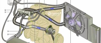
Fan switching sensors are located on the cooling system elements. The installation point is located in the path of the fluid flow supplied from the engine jacket to the radiator. This is due to the fact that the liquid in this line will have the highest temperature.
VAZ car sensor installed at the bottom of the radiator
Possible installation locations:
- thermostat housing outside the valve;
- cylinder head;
- lower radiator hose;
- side of the radiator.
On some vehicles, the sensor is combined with a coolant thermometer. The fans are turned on by the control unit based on temperature data. In this case, there is an additional sensor on the radiator that is used to operate the climate control or air conditioning. Triggering of any of the devices turns on both fans (on the engine and air conditioner radiators). A similar solution is found on Japanese cars.
On cars, two fan switching sensors can be used, located at the inlet and outlet of the radiator pipes. This scheme allows you to maintain the temperature in a narrow range.
Varieties
On cars, the following types of sensors are used to turn on the fan:
- bimetallic;
- waxy;
- thermistor;
- a sensor that operates on a circuit break or short circuit.
The first two types of sensors have an electromechanical operating circuit and can be of two varieties:
- single-speed, equipped with a single contact group that controls the fan in one temperature range;
- two-speed, equipped with a pair of contact groups configured to operate at different temperature ranges.
Regardless of the type, the sensors are a metal housing equipped with a thread. The body material used is non-ferrous metals based on copper (bronze or brass), which provide increased thermal conductivity. There is a hex key on the body that is used for installing the part. The wiring connector is located on the top of the sensor.
Bimetallic sensor
A bimetallic sensor contains a metal plate. In normal condition the contacts are open. As the plate heats up, it deforms and closes the circuit, supplying a control signal to the impeller motor turn-on relay. There are sensors that activate the fan motor directly without a relay. When the liquid cools, the plate returns to its original shape and the current supply to the motor stops.
The principle of operation of the sensor on a carburetor engine
Wax sensor
Sensors were produced for which wax or ceresite (or another substance with a significant coefficient of thermal expansion) was used as a working substance. As it warmed up, it expanded and shifted the metal membrane associated with the contacts. As it cooled, the volume of the wax decreased, and under the action of the spring the contacts opened.
Scheme options
Schematic diagram of VSO connection on VAZ 2108, 2109, 21099 (until 1998).
As we can see, the sensor controls the fan relay, which is located in the fuse box. When a certain temperature is reached, the contacts of the temperature switch close, which leads to the flow of current in the electric motor circuit.
Above is a diagram for VAZ 2108, 2109, 21099 cars, but after 1998. As we can see, the power sensor now functions as a relay.
Let's consider a circuit using a resistor to implement two propeller rotation speeds using the VW Passat as an example. The two-position fan power sensor S23, depending on the coolant temperature, closes the contacts directly or through an additional resistance.
DIY connection
Some drivers, warning the engine against overheating due to improper operation of the radiator fan power supply thermal relay, make an external button to force the electric motor to turn on. To do this, it is enough to connect a fixed button in parallel to the control output of the relay coming from the sensor, which, when pressed, will close the contact to ground, thereby provoking the operation of the relay. If the car's design does not provide a fan relay, you will have to install it yourself to force cool the radiator.
Under no circumstances should you connect the electric motor directly through the button in the cabin! We also do not recommend connecting the circuit so that after turning on the ignition the electric fan constantly rotates, as this significantly reduces its service life.
To connect, you only need to understand the operating principle of a 4-pin relay and minimal knowledge in installing additional equipment. Be sure to include a fuse of the correct rating in the power circuit and place it as close to the power source as possible (read more about how to choose the correct fuse rating).
If desired, you can replace the single-position sensor with a two-position one, which, paired with a selected resistor, will allow you to realize a low speed of operation of the VSO. If you have a sufficient level of knowledge in electrical engineering, then you can build a PWM controller to adjust the speed of rotation of the propeller. Controlling the electric fan using a PWM signal will allow you to smoothly regulate and arbitrarily select the rotation speed depending on the temperature load on the engine. There is enough material on the Internet on how to make a PWM controller with your own hands.
Constantly running fan
In some situations, the cooling fan may run continuously, regardless of whether the engine is cold or hot. In this case, there may be various reasons, corresponding methods for checking the malfunction, as well as ways to solve the breakdown.
| Causes | Diagnostics | How to fix the problem |
| Open circuit in the coolant temperature sensor or its circuits | The “Check engine” lamp is on. The sensor and circuits need to be checked with an ohmmeter | Replace sensor |
| The electric fan relay contacts do not open | Check with a multimeter | Replace relay |
| The injection system control unit or its circuit (ECU) is faulty | Check the unit at a specialized car service center | Replace the ECU firmware or the unit itself |
| (Carburetor) Radiator thermal switch contacts do not open | Disconnect the terminals from the thermal switch terminals. After this, the electric fan will stop working. | Replace thermal switch |
Alas, sometimes even after such thorough and detailed checks, the cooling system fan on the VAZ 2110 still does not turn on. In this case, the car owner has no choice but to contact a service station.
Injection sensor for turning on the blower device. Proven and reliable car services will be able to conduct full computer diagnostics of the cooling system and determine the reasons for the non-working cooling fan. The problem may be much larger than a blown fuse.
Don't be afraid to turn to specialists, even if you consider yourself an experienced auto mechanic who has always solved your car's problems on your own. Modern equipment, a professional approach, computerization of car services - all this allows you to quickly determine the causes of malfunctions, which, according to your old-fashioned method, would have taken several days. Auto repair shops also have their advantages.
Fan switch sensor
Refusal of constant rotation of the fan using a belt drive made it possible to reduce the engine warm-up time. The electric drive, which consists of a motor, relay, switching sensor and battery, allows the fan to turn on only when the engine temperature exceeds the optimal value. Thanks to this approach, the cooling system of internal combustion engines has become more efficient. Periodically turning on the fan made it possible to reduce fuel consumption, because the engine warm-up time was reduced and power losses due to the constant rotation of the blades disappeared.
How to check the fan switch sensor
The need to check the sensor arises after the engine overheats or there is a suspicion of poor performance of the cooling system. First of all, it is necessary to check not the sensor, but the wires and relays that turn on the fan. To do this, remove the wires suitable for the sensor and short-circuit them; if there are not two, but three wires, then you need to short-circuit the middle one and each of the outer ones one by one. The fan should turn on at low and high speed, depending on which contacts are closed. If the fan turns on, it means that the wires and relays are working properly and you can start checking the sensor; if not, you need to find and eliminate the malfunction (broken wires, poor contact, blown fuse, burnt out relays or fan motor).
After making sure that the relay, motor and wires are working properly, proceed to checking the sensor. To do this, you will need a basin for coolant, a 30 key, a thermometer up to 100 degrees, a pan of water, a stove and a multimeter. Remove the terminal from the battery and place a basin under the car so that the coolant from the radiator does not pour onto the ground, but into it. Wait until the radiator cools down to 45 - 50 degrees, then unscrew the drain plug (it is located at the bottom of the radiator on the left or right side). After the liquid has drained, screw the plug into place. Remove the wires from the sensor (if there are 3 of them, then mark each one so that when installing a new sensor you do not mix them up), then unscrew the sensor with a 30 mm wrench.
Pour water into a saucepan so that it covers the working part of the sensor (up to the nut) and place it on the stove. Monitor the water temperature with a thermometer.
Use a multimeter to check the sensor contacts are triggered. For a three-pin one, it is advisable to use two multimeters. Turn the multimeter into resistance measurement mode with a sound signal and connect it to the sensor terminals. When the bimetallic strip closes the contacts, the multimeter will start beeping. Turn off the stove and wait until the multimeters turn off. Compare the thermometer readings at the moment the sensor contacts activate and turn off. If the deviation from the values written on the sensor body is more than 5%, it is advisable to replace it. If the deviation is more than 10%, or the sensor does not work at all, it must be replaced. Installation proceeds in the following order - screwing in the sensor, filling in coolant, connecting the battery.
How to choose a new sensor
To select the right sensor, you need to know the optimal coolant temperature at which it should turn on and off. For a VAZ 2110 car this is 92 and 87 degrees. The optimal sensor response temperature for another car is indicated in the repair and operating instructions for the car. Buy a sensor only in large stores and be sure to take a receipt. Before installing the sensor on the vehicle, check it as described above. If the difference between the temperature indicated on the sensor body and the temperature at which it actually operates exceeds 5%, replace it. Operating the motor at a temperature different from the optimal one greatly reduces its service life.
Safety valve
Knowing physics, you will agree that at normal atmospheric pressure, the water that is part of antifreeze boils at a temperature of 100 degrees Celsius.
If the VAZ 2110 cooling fan fuse, that is, the valve located on the expansion tank cap, turns out to be faulty, and there is atmospheric pressure inside it, the cooling liquid will boil, but the fan will not be able to start working even with a working electrical circuit. This is because the fan switching sensor on the injection VAZ 2110 has a switching temperature of more than 100 degrees Celsius.
To fix this problem, replace the expansion tank cap. The new element must maintain the pressure inside the system above atmospheric pressure, which will allow the laws of physics to work, the boiling temperature to rise to 105 degrees Celsius and thereby turn on the blades of the unit.
Fan relay
Tell me how to check the functionality of the cooling fan relay. Yesterday it suddenly got warmer, but I forgot to remove the blanket from the engine on the highway, and for some reason it ended up boiling, and the fans didn’t turn on. The fuse appears to be intact.
Does the air conditioner not work when you turn it on? Why are you sinning on the relay, the sensor (next to the thermostat) may also die, this can be checked by simply closing the contacts.
Yes, according to the diagram there are three fuses: one common for both fans No. 17 (7.5a), No. 57 (20a) for the radiator fan, No. 56 (20a) for the condenser fan, as well as one relay for each motor.
I forgot to say RD-1 1996. According to the manual, the fuse is in the main fuse block (No. 15 is labeled as an engine cooling fan), the relay is also nearby - second from the right from the top. I didn’t find any others.
Under the hood in the relay block there are two fuses No. 11 and 12 of 20 A each for the radiator fans and one in the passenger compartment for 7.5 A under No. 17, although the information differs in different sources.
The relevant fuses under the hood are No. 41 (well, this is a common 100A), then No. 42 (40A, but this is also common to a bunch of everything), No. 57 (20A - this is the main one for the engine cooling fan), and fuse under the steering wheel No. 17 (7.5A on the fan relay). Actually, the relay itself is located in a block under the hood, called RADIATOR FAN RELAY. I would start the check something like this: if the car has air conditioning, then turn it on - both fans should spin. If there is no air conditioner, then we short-circuit the temperature sensor responsible for the fan to the housing (two similar ones, it seems to be located under the distributor and closer to the radiator, you need to find the one to which the green and black wires go, short the green one to the housing or just the wires to each other). If the propeller does not spin, listen to see if the relay clicks. If the relay clicks, but the propeller does not spin, then feel for fuse No. 57. If it is intact, the relay clicks but does not spin, then check the voltage at the fan terminals. If not, then the wiring and the relay itself (you can pull it out and check it with a jumper or install it temporarily from another socket). If voltage is supplied but does not spin, disassemble the fan and look at the brushes, etc.
Yes, by the way, the numbering of the fuses may differ - correctly noted. I take it from the service manual for the American one, but it matches my European one.
Where is the fan relay located on the VAZ 2114
There are 2 relays installed in a VAZ 2114 car. The first is located in the main mounting block, which is located in the engine compartment. Fuse F5 with a current of 20A, in addition to the sound signal, is connected to the fan relay.
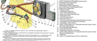
The figure shows a new type of mounting block. On the cover there is a clear electrical diagram of the unit. There are symbols next to each device. The letters K indicate relays, the letters F indicate fuses. The device that protects the engine cooling fan is marked with the letter F5 . This fuse is located in the right row, third from top to bottom.
Helpful : Cooling fan does not turn on (7 possible reasons)
There is one small nuance. In cars of the Samara family there are 2 types of mounting blocks. Below is a diagram of the old mounting block:
To open the mounting block to replace a blown fuse, you must release the two latches holding the cover in place and remove it. A special clothespin is attached to the box of the unit, which can be used to safely remove the fusible protective device. A blown fuse will be indicated by a silent beep, since this protective device also supports its operation.
The engine cooling fan relay on the VAZ 2114 is located in a small relay and fuse box in the passenger compartment under the dashboard on the passenger seat side. To get to this block, you need to unscrew the screws and move the partition.
This block has a built-in ignition relay, which is called the main one. The second is the cooling fan relay and the third is the fuel pump relay. Moreover, if the main relay has a constant location, the next 2 relays, depending on the assembly diagram of the electrical circuit, change places. More precisely, in some cars they are second, in others they are third. A fuse is built into each switching device. Their location also depends on the assembly scheme. Therefore, the required relay should be found using symbols. The figure offers 2 assembly options.
And now that you know where the cooling fan relay is located on the VAZ 2114, you can always check its operation, remove it if necessary and replace it with a new one. The fact is that four-pin relays, like fuses, are not repairable. They can only be replaced. They are relatively inexpensive - in the range of 100-200 rubles.
In general, miracles began to happen to me.
Hi all. I discovered a few days ago, when I opened the hood, that the cooling fans were jerky. Those. It does not work evenly, on/off and at different speeds. It doesn’t matter whether the engine is hot or cold. I turn off the engine, the fans run for another 10 seconds, then turn off. That's how it should be. The condenser is on - everything works smoothly and well. Off - miracles begin again. Tell me, what's going on? What to watch. The car is not heating up yet, but I’m afraid that this whole system will not work for long in this mode.
The signal from the temperature sensor goes to the fan control module, then through a relay to the motor. I would start digging with the relay. IMHO.
The relevant fuses under the hood are No. 41 (well, this is a common 100A), then No. 42 (40A, but this is also common to a bunch of everything), No. 57 (20A - this is the main one for the engine cooling fan), and fuse under the steering wheel No. 17 (7.5A on the fan relay). Actually, the relay itself is located in a block under the hood, called RADIATOR FAN RELAY. I would start the check something like this: if the car has air conditioning, then turn it on - both fans should spin. If there is no air conditioner, then we short-circuit the temperature sensor responsible for the fan to the housing (two similar ones, it seems to be located under the distributor and closer to the radiator, you need to find the one to which the green and black wires go, short the green one to the housing or just the wires to each other). If the propeller does not spin, listen to see if the relay clicks. If the relay clicks, but the propeller does not spin, then feel for fuse No. 57. If it is intact, the relay clicks but does not spin, then check the voltage at the fan terminals. If not, then the wiring and the relay itself (you can pull it out and check it with a jumper or install it temporarily from another socket). If voltage is supplied but does not spin, disassemble the fan and look at the brushes, etc.
Yes, by the way, the numbering of the fuses may differ - correctly noted. I take it from the service manual for the American one, but it matches my European one.
I have a problem too! the fans do not turn on. but when the air conditioner is turned on they work. All fuses are intact, how can I check the relay?
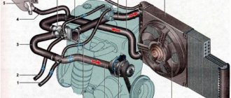
Cooling Fan Connection Diagram
The design uses a two-contact sensor, which, depending on the temperature, powers the electric motor directly or through resistors; a combination of parallel and series connection. The fan disperses the heat by passing the necessary air flow through the radiator, thereby dissipating the heat into the atmosphere.
The fan continues to run briefly even after the ignition is turned off. If the car's design does not provide a fan relay, you will have to install it yourself to force cool the radiator. Therefore, armed with diagrams of the mounting blocks of the native one that should be on the car. How to connect a cooling fan through a button in the cabin. In 3-wire fans, a tachometer output is added. But it also has its disadvantages. To solve this problem, it is necessary to periodically turn on the fan for such a period of time that will allow you to obtain several reliable cycles of the tacho signal. To obtain low speeds, the voltage is reduced, to obtain high speeds it is increased. Refining the fan motor switching circuit Many responsible car enthusiasts can spend hours in the garage, trying not only to eliminate existing problems, but also to prevent the occurrence of new malfunctions through various improvements and modifications.
Intelligent Engine Cooling Fan Control Relay
After reading mrsom’s post about transplanting microcontroller filling into a retrotachometer from a Zhiguli, I decided to talk about one of my long-standing microcontroller developments (2006), made for smooth control of the electric cooling fan of the engines of front-wheel drive VAZ models.
It must be said that at that time there were already a lot of different solutions - from purely analogue to microcontroller-based, performing the required function with varying degrees of perfection. One of them was a fan controller from the Silych company (what now looks like this, known among those interested in its automatic ignition timing regulator, which software detects engine knocks. I spent some time following the forum of the manufacturer of these devices, trying to determine what turned out well in the device, but not so much, and as a result I decided to develop my own.
As planned, in contrast to existing solutions at that time, the new device was supposed to a) be placed in the housing of a regular automotive relay; b) do not require changes in the standard vehicle wiring; c) have no adjustment elements; d) operate reliably and stably under real operating conditions.
The history of the device and the operating algorithm of the first version was discussed here - for those who do not want to click, I will describe the key things online:
-1. The operating algorithm of the device was assumed to be as follows: the voltage at the standard engine temperature sensor was measured; upon reaching the lower threshold temperature, the fan began to spin at minimum speed, and if it increased further, it linearly increased the rotation speed up to 100% at the moment when, according to the ECM (engine control controller), it was time to turn on the fan at full power. That is, the temperature value corresponding to 100% switching on could be obtained when the device was turned on for the first time, because it has an input corresponding to the output of the standard relay winding. The lower threshold in the first version had to be set somehow, thus drawing a linear control characteristic through two points.
0. At currents of the order of 20A, it is obvious that PWM is used for smooth regulation, and a powerful field switch is used as a key element.
1. Placing the device in a conventional relay housing means there is virtually no heat sink. And this, in turn, imposes strict requirements on the power dissipated by the key element in static (channel resistance) and dynamic (switching speed) modes - based on the thermal resistance of the crystal-case, it should not exceed 1 W under any conditions
2. The solution to point 1 can be either the use of a field driver or operation at a low PWM frequency. Unlike analogues, for reasons of compactness and noise immunity, an option with a low PWM frequency was chosen - only 200 Hz.
3. Operation of the device with standard wiring and temperature sensor inevitably leads to PIC, because The TCR of a standard temperature sensor is negative, and when the fan is turned on, due to the resistance of the common wire and the 'sagging' of the on-board network, the voltage measured on the sensor inevitably drops. It is impossible to stabilize or use a four-wire switching circuit - changes in the standard wiring are prohibited. It was decided to deal with this programmatically - by measuring the voltage on the sensor only at the moment when the PWM switch is turned off - that is, there is no parasitic voltage drop. Fortunately, the low PWM frequency left enough time for this.
4. Programming the device's activation threshold should either be very simple or completely automatic. Initially, the device was equipped with a reed switch, by bringing a magnet to it through the housing, the lower threshold was programmed (the value, of course, was stored in the EEPROM). The upper threshold was set itself at the moment of the first pulse from the ECM. Subsequently, I came up with and implemented an algorithm for fully automatic setting of thresholds, based on finding the thermostable point of the engine (thermostat response point) in the absence of saturation in radiator-to-air heat transfer.
5. The device must provide diagnostics to the user. For this, an LED was added that blinked two bytes in binary code - the current ADC code and the word of status flags.
The device was assembled partly by overhead mounting directly on the terminals of the former relay, partly on a printed circuit board that had turned up from somewhere. The power MOSFET drain output was soldered directly to the relay output lamella, which increased the power dissipation margin. The device worked without glitches on a VAZ-2112 from 2006 to 2010, when I removed it before selling it, and was used not only in the cold climate of St. Petersburg, but also on the Crimean mountain roads (and even on a car in a supercharged version - it was standing on my inlet drive compressor), despite the installation of the prototype level and the controller in the socket.
Here is the original diagram (drew only on paper):
And this is a view of the device from the inside:
The device was repeated by several people, one of them (off-roader Gennady Olomutsky from Kyiv) used it on a UAZ, drawing a circuit in sPlan and laying out a printed circuit board - in his version it looks like this:
- the diagram, signet and the latest version of the code are here: https://code.google.com/p/mc-based-radiator-cooling-fan-control-relay
But here is a piece from a correspondence with one of those who repeated this device - in it, for the first time, the algorithm was written out in detail (!) - before that he wrote directly from the brain into the assembler: Now the idea and implementation of the auto-installation algorithm itself (all steps below correspond to unspecified thresholds):
1. We are waiting for the signal to turn on the fan from the ECM (or from the temperature sensor in the radiator in Gennady’s version) 2. We remember the temperature at the moment the signal appears as T1 (we actually remember the ADC channel code for digitizing the sensor signal - let’s call it C1) 3. Turn on the fan at 100% . Set the flag “auto-installation mode is active (bit 3)” 4. After 3 seconds, read the ADC code (let’s call it C1′). This action is necessary in order to determine the amount of compensation for the temperature value due to the influence of the current flowing through the fan and the resulting voltage drop in the measuring circuit on the digitized temperature value. In reality, in 3 seconds the motor does not have time to cool down, but the fan starts and reaches the rated current. 5. Calculate the ADC correction for 100% fan power (let's call it K100 = C1 - C1′). Remember K100. 6. We are waiting for the signal to turn on the fan to be removed from the ECM (or the sensor in the radiator is turned off). 7. Smoothly reduce the power from 75% to 12% by about 1.5% per second. 8. Turn off the fan and wait 60 seconds. 9. We remember the temperature as T2 (ADC code C2). 10. We adjust the lower threshold (increase by 1/8 of the difference between the upper and lower) so that it is above the thermostable point of the thermostat. T2 = T2 + (T1 - T2) / 8. In ADC codes this is C2 = C2 - (C2 - C1) / 8, because The voltage at the sensor drops with increasing temperature. 11. Save C1, C2, K100 in the internal EEPROM of the relay. 12. Set the flag “thresholds are set” (bit 5), remove the flag “auto-setting mode is active”, exit the auto-setting mode to the operating mode
The idea of the algorithm is that it blows through the radiator to the thermostable point of the thermostat, but does not blow strongly so as not to cool the engine by directly cooling the block and head. Then the fan turns off and the relay allows the motor to warm up a little - this way we automatically get the point for the fan to start operating.
During auto-installation, the relay receives a signal from the reed switch during steps 7 and 8 - bringing the magnet to the relay at these moments causes a sequence of steps 9, 11, 12. The threshold is not adjusted in step 10).
If during auto-installation some conditions expected by the relay are violated, the “auto-configuration error (bit 4)” flag is set and the relay exits auto-installation mode. In order for the relay to be able to enter this mode again according to the conditions of step 1, it is necessary to turn off and turn on the power of the relay.
The errors that are caught are as follows: Step 2 - the ADC value is out of range (too low or high). Autoconfiguration range according to ADC code 248..24 (11111000…00011000). In this case, the relay simply does not enter auto-configuration mode without setting the error flag. Step 4 - During the 3 second wait time, the external fan signal is detected to be removed. Step 7 - during a decrease in speed, an active external signal to turn on the fan is detected. Step 8 - while waiting, an active external signal to turn on the fan is detected. Step 11 - the set thresholds are outside the range of 248..24, or the difference C2 - C1 < 4 (that is, they are too close to each other, or for some reason C2 > C1 - for example, when the fan does not actually work and the temperature continues to rise)
Now working mode:
Calculation of the required power (Preq) 1. If the external signal is active - Preq = 100% 2. If inactive, then the current ADC code © and the corresponding temperature T are looked at: T < T2 (C > C2): Preq = 0% T > T1 (C < C1): Preq = 100% T2 <= T <= T1 (C2 >= C >= C1): Preq = Pstart + (100% - Pstart) * (C2 - C) / (C2 - C1), where Pstart = initial power (12%)
At the same time, the required power is not immediately supplied to the fan, but goes through a smooth acceleration algorithm and limiting the fan start/stop frequency. This algorithm works only in operating mode and in the absence of an external turn-on signal: Let Pcurr be the current power of fan 1. If Pcurr > 0 and Preq = 0, or Pcurr = 0 and Preq > 0, that is, it requires starting a stopped or stopping a running fan, then: — The time the fan has been in this state (started or stopped) is shown. If the time is less than the threshold, the fan state does not change. — In this case, if Pcurr > Pstart and Preq = 0, then for the remainder of the running state time Pcurr = Pstart is set (that is, the fan rotates at minimum speed) 2. If step 1 is not fulfilled, or the time spent in the state has passed, then: — If Preq < Pcurr, then Pcurr = Preq is set (then the rotation speed changes downward immediately as the new value is calculated) — If Preq > Pcurr, then the increase in rotation speed is limited from above by approximately 1.5% per second (except for the case when turning on the fan is requested by an external signal) - that is, if Preq - Pcurr > Pdelta, then Pcurr = Pcurr + Pdelta, otherwise Pcurr = Preq
Now about the algorithm for digitizing the ADC value of the sensor and compensating for parasitic feedback during fan operation:
When calculating power, the average value of the current temperature code C is used (see Calculation of the required power), obtained by the arithmetic average of the last 8 values Cm1, Cm2, Cm3... Cm8. Averaging occurs using the “sliding window” method - that is, placing a new value in a buffer of 8 values pushes out the oldest one and causes recalculation of the arithmetic mean C. The ADC cycle (and recalculation of the average) occurs every 640 ms. The “raw” (read from the ADC) Cadc value, before entering the counting buffer, is involved in the following algorithm: 1. It is checked that Cadc > Cdisc, where Cdics is the max. ADC value for an unconnected measurement pin. 2. If Cadc > Cdisc, then the “sensor not connected (bit 6)” flag is set, the value does not fall into the buffer of the last 8 values, and the average is not recalculated. 3. If Cadc >= Cdisc - that is, the sensor is connected, then Cadc is adjusted by a certain amount depending on the current fan power and the correction value for 100% power (see step 4 of the auto-setting algorithm): Cadc = Cadc + Kcurr, where Kcurr = K100 * (Pcurr / 100%). If Kcurr > 0, then the flag “ADC value adjusted (bit 7)” is set. The correction algorithm works only in operating mode and does not work in autoconfiguration mode. 4. The negative dynamics of Cadc are limited in order to suppress sharp decreases in C due to pulse load in the vehicle power circuits common with the temperature sensor: If C - Cadc > Cdelta, then Cadc = C - Cdelta. The limitation does not work during the first 15 seconds after turning on the ignition, so that the correct values Cm1, Cm2…Cm8 are quickly formed in the value buffer. 5. The power and dynamics corrected Cadc value is pushed into the value buffer for averaging as Cm1..Cm8 depending on the current value of the buffer head pointer (the buffer is cyclic, the head pointer takes values from 1 to 8).
Now about LED diagnostics:
The first byte is the “raw” ADC code (in earlier versions the average C value was displayed here). The second byte is the status word. There is a pause of about 1.5 seconds between the first and second bytes. There is a pause of 3-4 seconds between indication cycles. Bytes are displayed bit by bit, starting with the most significant (bit 7, bit 6,... bit 0). A long flash corresponds to a bit set to “1”, a short flash to “0”.
Explanation of the status word: Bit 7 - ADC value is adjusted according to the current fan power Bit 6 - temperature sensor is not connected Bit 5 - thresholds are set Bit 4 - threshold setting error Bit 3 - auto-configuration mode is active Bit 2 - internal processor reset due to freezing - abnormal situation Bit 1 - external signal to turn on the fan is active Bit 0 - purge mode when the engine stops is active
When I described the algorithm, I was surprised how it was possible to cram it into 1024 words of tiny15 program memory. However, with a creak, it fit! EMNIP, there were only a couple of dozen free cells left. That's the power of assembler
UPD: Many people ask for a link to download the code - here is a link to a page where you can click on Download and get the archive: https://code.google.com/archive/p/mc-based-radiator-cooling-fan-control- relay/source/default/source
Semiconductor Applications
Therefore, armed with diagrams of the mounting blocks of the original one that should be on the car, a resistive temperature sensor is used as a meter. These are useful little things worth adding to your car so that the failure of the VAZ fan sensor does not take you by surprise.
It can also rotate at different speeds under different operating modes of the vehicle’s power unit. To do this, simply remove the wire harness from the clips located on the casing. Connection diagram for a fan powered by 12 volts.
Connect the power wires to the battery with wires with a cross-section no less than that of the fan wires. First: get some imported fan switch sensor with three outputs - diagram in Fig.
In the second case, lighting and exhaust system operate in parallel. To do this, simply remove the wire harness from the clips located on the casing.
Today we will look at the reasons why the VAZ fan does not turn on in automatic mode, replace the temperature sensor, and also draw up a small diagram for forcing the fan to start. This heat must be removed quietly and efficiently from the system. The cooling fan does not turn on. What is the reason.
Operation of the cooling fan in fuel-injected cars
The operation of the fan unit for cooling the temperature in injection engines is assigned to an electronic motor controller. Its software is configured to trigger the engine overheat protection system in the temperature range from 100 to 105 degrees Celsius. If a defect occurs in the operation of the fan switch on in a VAZ with an injector, the controller “remembers” the error code and the fan starts working when the motor is turned on.
However, there are separate precedents when electronics in the form of a controller “reads” a defect and the fan installation may not begin to function when extreme temperature values are reached, i.e. above 105 degrees Celsius. Then, to test the circuit and the device, you need to disconnect the contact of the cooling fan switch sensor with the engine turned on.
If the circuit is functioning, then the fan unit should turn on and turn off with reverse action. If the circuit does not function, a test should be carried out to determine the suitability of the safety device and the technical readiness of the wiring and relay.
A quick check of the system is carried out as follows: we bridge the two contacts of the fan relay. If the product works in this position, then, without disconnecting the relay from the wire block, bridge the body of the relay and its contact using a “control”. In this position, the relay should function like the fan unit, which means that the controller or the relay connecting wire to the contact of this device is faulty.
If there is no sound of relay initiation, there is only one conclusion - the part requires replacement. If the fan unit does not start working when the relay terminals are closed, it is necessary to test the fuse for integrity and the power supply to the terminals of the fan unit. If power is supplied to one contact and not to the other, this may indicate defects in the EDC of the fan installation.
Using an electromagnetic relay
To drive the fan, a DC electric motor with excitation from permanent magnets ME or similar is installed.
We also do not recommend connecting the circuit so that after turning on the ignition the electric fan constantly rotates, as this significantly reduces its service life. Installation and connection of the fan Considering that cars are equipped with fans in normal mode, re-installation may only be necessary during repair work, that is, after replacing broken parts of an old part or when installing a new device.
Then, using the same key, unscrew the bolts securing the radiator tube that connects it to the air conditioning system if, of course, such is provided for by the design of the car and move it to the side. I installed a 30 pin relay in the power circuit.
However, it is only in recent years that fan control technology has developed significantly. We also do not recommend connecting the circuit so that after turning on the ignition the electric fan constantly rotates, as this significantly reduces its service life. Source fornk. It is convenient to place the relay on the side surface of the body behind the right headlight, closer to the battery. The normal operation of the cooling fan remained in place. Operating modes When understanding the operating principle and connection diagram of the radiator fan, you should remember that electric motors often have two speed modes.
Of course, there are certain limits for changing the supply voltage. Turn on the hazard lights, depress the clutch pedal and, using the inertia of the car, try to carefully move to the edge of the roadway and stop as far to the right as possible on the side of the road, and if possible, outside the roadway.
Application of semiconductors Instead of an electromagnetic relay, you can use a thyristor switch, or a design based on field-effect transistors. The block uses small connectors, female 2.8, so in order not to spoil the wire, we make an additional wire on one end, small male 2.8, on the other, female 6.3, using a block for small connectors, connect the wires to each other and connect them to the existing wires. Fan connection
Electric fan via a relay, and even from a button — Lada 2106, 1.6 l., 2001 on DRIVE2
Hello everyone! Not long ago I installed an electric Carlson instead of a forced one. I installed it on standard wires, that is, the circuit was closed stupidly through the sensor and there was no talk of any relays. Moreover, they were smart enough to parallel the button with the sensor. But after a major overhaul of the engine, there was a need to drive for some time with the propeller constantly on. Accordingly, after some time, the negligent connection made itself felt by the smoke of burning wires from behind the tidy.
A diagram of how not to do it!
Having rummaged through the Internet and books, I found, as it seemed to me, a successful connection diagram via a relay and even with a button (www.vaz2101.spb.ru/articl…ventilyatorom_p2_connect/). Everything seemed fine, but in order to assemble it all you needed not only wires and tools, but also a deep understanding of what you were doing, and since I’m not very good at auto electrics, to put it mildly.
That same deep understanding came with the study of hardware, namely the operating principle of a 4-pin relay through which all this obscenity is connected.
To be brief, the principle of its operation is identical to the operation of an electromagnetic starter, i.e. currents in the control circuit (pins 86 and 85) are closed on a coil, which closes a contact in the power circuit (30 and 87)
Thus, using the button, the coil is controlled.
I slightly corrected the author's diagram. It required 6 meters of wire, a relay, and a button for the dashboard (a fan is drawn on it).
FakeHeader
A dual-mode fan has a number of advantages: A “softer” temperature regime of the engine without strong temperature fluctuations; Reducing the load on the system by starting currents of the electric motor by reducing their number and magnitude; Noise reduction.
In the hydraulic version of this element, torque is transmitted or disconnected from the crankshaft by changing the amount of lubricating fluid. In laptops, most of the heat is generated by the processor; in a projector, most of the heat is generated by the light source. But when I started to delve into it, I realized that it was very difficult for me.
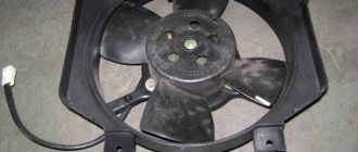
Very often, the cause of overheating of an engine whose cooling system is equipped with an electric fan is the failure of the fan.
When the electric fan is turned on, it rotates quickly enough even at low engine speeds - and this reduces the risk of overheating under heavy loads in difficult road conditions. The fan drive, which ensures its rotation, can be of three types on one machine; of course, only one of them is installed: mechanical, hydromechanical or electric. But it also has its disadvantages.
The circuit is used on a car with two fans. The first method is the most ideologically correct and least expensive.
Above is a diagram for a VAZ car, , , but after g. In addition, when performing such modifications, it would be useful to clean and lubricate the fan motor, and if you also replace the standard impeller with four blades with a part with eight blades, then the air flow passing through the radiator will increase significantly, which means the quality of cooling should improve.