Bleeding the hydraulic brake system
We pump the brakes to remove air from the hydraulic drive after it has depressurized when replacing the master cylinder, wheel brake wheel cylinders, hoses, tubes, as well as in case of replacing the working fluid or when the brake pedal becomes “soft”. We remove air from the system when the engine is not running, first from one circuit and then from the other in the following sequence: – the brake mechanism of the right rear wheel; – brake mechanism of the left front wheel; – brake mechanism of the left rear wheel; – brake mechanism of the right front wheel. If air gets into one of the circuits, it is enough to bleed only this circuit, and not the entire hydraulic drive. Before pumping, check the level of working fluid in the brake system hydraulic reservoir and, if necessary, add fluid (see “Checking the fluid level in the brake hydraulic reservoir,” page 42). We bleed the brakes with an assistant. If the rear wheels are hanging...
...insert a screwdriver between the lever and the plate spring of the pressure regulator in the hydraulic drive of the brake mechanisms of the rear wheels, fixing the regulator piston in the recessed position. We clean the brake bleeder fitting of the right rear wheel from dirt...
...and remove the protective cap from it. Use a spanner wrench or an “8” socket to loosen the tightening of the bleeder fitting. We put a hose on the fitting, and immerse its free end in a container partially filled with working fluid. An assistant should vigorously press the brake pedal all the way 4-5 times and keep it pressed.
Using the “8” wrench, unscrew the bleeder fitting 1/2–3/4 turn. In this case, liquid with air bubbles will flow out of the hose, and the brake pedal should be pressed all the way. As soon as the liquid stops flowing out of the hose, tighten the fitting and only after that can the assistant release the pedal. We repeat pumping until air bubbles no longer appear in the liquid coming out of the hose. We remove the hose, wipe the bleeder fitting dry and put a protective cap on it. We pump as described above...
...brake mechanism of the left front wheel. Similarly, we bleed the brake mechanisms of the other circuit. When pumping, you need to monitor the fluid level in the brake hydraulic reservoir and add fluid if necessary. If, when you press the brake pedal, you feel its “softness” and increased travel, it means there is air left in the system. In this case, we repeat pumping until the pedal becomes “hard”, i.e., when pressed, go no more than half the distance to the floor. If air cannot be removed, check the tightness of connections, pipelines, hoses, master and working cylinders. We tighten leaking connections, replace faulty main and working cylinders (see “Brake system”).
Below are instructions for checking the brake system of the Russian class “B” sedan Lada Priora. It includes all the important points and connecting parts of the braking system.
To imagine a car without brakes is tantamount to an uncontrollable horse. When leaving the garage, this is the first thing to check and never put off repairing the brake system. We'll tell you about the brake system parts, their testing and their prices.
ABS device on Priora
Like most modern car systems, ABS is computer controlled. But in addition to the electronic control unit, it also includes several sensors and actuators. The entire system consists of several elements.
- Electronic control unit (ECU).
- Wheel hub sensors 4 pcs.
- Brake fluid pressure valves in the system 4 pcs.
- EVN (electric return pump).
- Indicator lamp on the instrument panel.
Despite all its apparent simplicity, this is a rather complex and high-tech system. Each sensor transmits data on the rotation speed of the Priora wheel to the electronic control unit. Based on the data received, the control unit sends a signal to the brake system valve, which, when the brake pedal is pressed, releasing pressure, prevents the wheels from completely locking and the car from starting to skid uncontrollably.
Anti-lock brake control unit in hydraulic unit
Structurally, on Priora, ABS control units are mounted together with EWH and pressure control valves into one unit - a hydraulic unit. It is located on the left front side member of the vehicle. The hydraulic unit is connected to the entire system via common wiring. It includes pipes for supplying brake fluid to the working cylinders. An EWH is also installed here, increasing the pressure in the system.
Wheel hub sensor
The sensors that transmit wheel speed data to the control unit are made according to the Hall sensor principle. By the way, this principle is used in most rotation sensors - the voltage change on the semiconductor of the sensor depending on the passage of a test point next to it on the rotating disk. The control unit controls the valves depending on the signals received from the ABS sensors.
ABS malfunction warning lamp on the Priora instrument panel
What Priora racers talk about - "ABS sensor turned on" - is actually a warning light for servicing the anti-lock braking system. When you turn on the ignition, the orange “ABS” sign lights up on the dashboard for about three seconds. If the system is operating normally, the light will go out after three to four seconds. In general, the principle of signaling from the “ABS sensor” is the same as that of a traffic light on the main computer of a car, the well-known “checker”.
Car braking distance
First of all, it is necessary to calculate the braking distance of the Lada Priora car. According to the rule, it should be about 12 m. In order to find out this distance, you must first fill the brake fluid tank full.
Then on a flat road you need to accelerate to 40 km/h and then brake sharply. The distance from the start of braking and the place where the car stops is the braking distance. If it exceeds the norm, then the system is in an unusable state. For more accurate results, it is recommended to do this procedure several times.
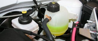
Brake fluid level
Brake fluid is one of the most important elements of the braking system. Its insufficient level can lead to irreparable consequences. Therefore, it is important to check the fluid level before using the vehicle or when the special brake fluid level light in the tank comes on.
Before starting work, use a rag to wipe off any dirt on the brake cylinder to prevent dirt from getting inside. Open the barrel. The liquid level can be seen by looking inside the barrel; it should not be below the minimum mark. If wear on the brake pads is noticeable and the fluid is at a minimum, you must fill in new fluid before unscrewing the terminal wires.
Then close the tank, attach the tip and check the liquid level using the emergency level sensor. If the light comes on, the system is OK.
Description of design
The service brake system is hydraulic, dual-circuit, with diagonally separated circuits. In normal mode, when the system is working properly, both circuits operate. If one of the circuits fails (depressurizes), the other circuit provides braking to the vehicle, although with less efficiency.
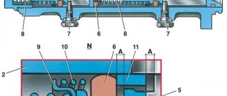
Elements of the brake system : 1 — front wheel brake disc; 2 — front wheel brake tube; 3 — front wheel brake hose; 4 — hydraulic drive reservoir; 5 — main brake cylinder; 6 — vacuum booster; 7 — brake pedal; 8 — rear wheel brake tube; 9 — pressure regulator; 10 — rear wheel brake mechanism; 11 — rear wheel brake hose; 12 - floating bracket
The service brake system includes wheel brakes, a pedal assembly, a vacuum booster, a master cylinder, a hydraulic reservoir, a pressure regulator in the rear wheel brakes, as well as connecting tubes and hoses. The brake pedal is a suspended type. A brake signal switch is installed in the pedal bracket - its contacts close when the brake pedal is pressed.
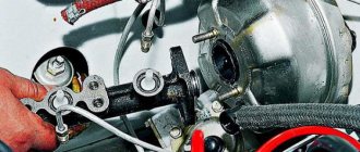
Pedal assembly with vacuum booster and main brake cylinder : 1 - brake pedal;
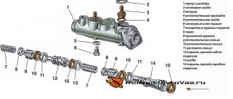
2 — brake pedal bracket; 3 - vacuum booster; 4 — hydraulic drive reservoir; 5 - main brake cylinder The vacuum brake booster is located between the brake pedal and the main brake cylinder and is attached with two nuts to the brake pedal bracket, which, in turn, is attached to the body. The vacuum amplifier is non-separable; if it fails, it is replaced with a new one. The brake master cylinder is attached to the vacuum booster housing with two studs. On top of the cylinder there is a reservoir for the hydraulic drive of the brake system, which contains a supply of fluid. There are markings for the maximum and minimum liquid levels on the tank body, and a liquid level sensor is installed in the tank lid, which, when the liquid level drops below o, turns on the alarm in the instrument cluster. When you press the brake pedal, the pistons of the master cylinder move, creating pressure in the hydraulic drive, which is supplied through tubes and hoses to the working cylinders of the wheel brake mechanisms.
Front wheel brake mechanism : 1 - shoe guide;
2 — caliper; 3 — brake pads; 4 — brake disc; 5 — brake shield; 6 — locking plate; 7 — screw securing the cylinder body to the caliper; 8 — hydraulic brake bleeder fitting; 9 — wheel cylinder; 10 — bolt securing the cylinder to the guide pin; 11 — guide pin; 12 — guide pin cover The front wheel brake mechanism is a disk one, with a floating caliper, which includes a caliper and a single-piston wheel cylinder, tightened together with two screws. The brake shoe guide is attached to the steering knuckle, and the bracket is attached with two bolts to the guide pins installed in the shoe guide holes. Protective rubber covers are installed on the fingers. Grease is placed in the holes for the pins of the pad guide. The brake pads are pressed against the guide grooves by springs. When braking, the fluid pressure in the hydraulic brake mechanism increases, and the piston, moving out of the wheel cylinder, presses the inner brake pad against the disc. Then the bracket (by moving the guide pins in the holes of the pad guide) moves relative to the disc, pressing the outer brake pad against it. In the cylinder body, attached to the caliper, there is a piston with a rubber sealing ring of rectangular cross-section. Due to the elasticity of this ring, a constant optimal gap is maintained between the disc and the brake pads.
Elements of the front wheel brake mechanism : 1 - bolt securing the cylinder to the guide pin with a locking plate; 2 — screw securing the cylinder to the caliper; 3 - cylinder; 4 - block; 5 — caliper; 6 - guide pin; 7 — guide pin cover; 8 — pad guide
Rear wheel brake mechanism : 1 - lower tension spring;
2 — front block; 3 - pressure spring; 4 — spacer bar; 5 - working cylinder; 6 — upper tension spring; 7 — parking brake drive lever; 8 — rear block; 9 — tip of the parking brake cable. The rear wheel brake mechanism is drum-type, with a two-piston wheel cylinder, two brake pads and a device for automatically adjusting the gap between the pads and the drum. The automatic clearance adjustment device is located in the wheel cylinder. The main element of the device is a steel split thrust ring mounted on the piston with an axial clearance of 1.25–1.65 mm. The thrust rings (two per cylinder) are inserted into the cylinder with tension, providing a shear force along the cylinder surface of at least 350 N, which exceeds the force of the brake shoe tension springs. When the brake linings wear, the thrust rings shift under the action of the pistons by the amount of wear.
Elements of the rear wheel brake mechanism : 1 - front block;
2 - pressure spring; 3 - spacer bar; 4 - upper tension spring; 5 - finger; 6 — washer; 7 - cotter pin; 8 — rear block; 9 — parking brake drive lever; 10 - lower tension spring If the cylinder mirror is damaged due to mechanical impurities in the brake fluid, or due to corrosion (presence of water in the brake fluid), the rings may “sour” in the cylinder and one or even both pistons will lose mobility. In this case, the cylinders must be replaced.
Pressure regulator in the hydraulic drive of the brake mechanisms of the rear wheels : 1 - earring; 2 - bracket; 3 - elastic lever; 4 — bracket; 5 - drive; 6 - pressure regulator
Brake pads
Also, the main elements of the braking system include brake pads for the front and rear mechanisms.
For the first case, put the car on a jack and remove the front wheels. Then you should turn the steering wheel and monitor the brake mechanism. The thickness of the pads should not be less than 1.5 mm. If the value does not correspond to the specified value, all pads should be replaced. You should also check the performance of the piston. If there are any defects, it should also be replaced.
For the second case, you must first unscrew the rear wheel brake plug. Next, inspect the thickness of the pads; if at least one of them does not correspond to the above size, all pads are replaced.
What is ABS
The anti-lock braking system was developed when it became clear that when the wheels became heavily jammed, the car became unstable and difficult to control. In addition, the quality of braking did not improve, and the car practically drove off the road. Therefore, a system was developed that, by adjusting the pressure in the brake system pipes, allows the wheels to turn slightly. This significantly improves vehicle dynamics, allowing the driver to drive more safely. But despite its apparent simplicity, this is a rather complex process that requires the coordinated operation of many mechanisms included in the anti-lock brake system. If any component of the instrument panel malfunctions, the warning light comes on.
Free pedal travel
The next point in checking the system is to measure the brake pedal play. Typically it should not exceed 5 mm. Using a ruler, measure the distance of the pedal to the floor. Then start pressing the pedal and the moment you feel resistance, measure the distance again.
Less or more free play can create many problems. In the first case, the brake pads may not work due to pressure, and in the second case, the play can lead to late application of the brakes. If performance is unsatisfactory, parts should be replaced.
Design features of Lada Priora car brakes
The car is equipped with two braking systems - working and parking.
The service braking system is designed to reduce the speed of the vehicle, until it comes to a complete stop and briefly holds the vehicle stationary.
The service brake system is dual-circuit, diagonal, hydraulically driven, and consists of a master cylinder with a vacuum booster, four wheel brakes and a fluid pressure regulator in the rear brakes.
The front wheel brakes are ventilated discs, the rear wheels are drum brakes.
Each of the car’s circuits includes brake mechanisms for two wheels: one front and one rear, located diagonally on the car.
One circuit includes the brake mechanisms of the front right and rear left tracks, and the second circuit includes the brake mechanisms of the front left and rear right tracks.
If one circuit fails, the second circuit, albeit with less efficiency, will ensure the vehicle stops.