Daewoo Nexia fuses
The Daewoo Nexia sedan is equipped with an electrical system with a negative contact (“ground”) to the car body.
The standard voltage of the on-board network is 12 volts. To protect the electrical equipment of the machine from short circuits or overloads, the main circuits are protected by fuses.
Nexia with an 8-valve engine and a 16-valve modification have identical electrical circuits.
The way fuses work is to open the electrical connection if a certain current is exceeded. In the event of an emergency electrical situation, the current-carrying fuse element is destroyed (blown), protecting electrical units from breakdown, and the car itself from possible fire.
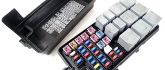
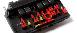
Nexia uses flat blade (fork) type fuses, standard ATO size, 19 mm high. The rated current in amperes is marked on the top surface of each fuse. For ease of identification, fuses of different ratings have a specific body color, but not all manufacturers follow this rule.
VESKO-TRANS.RU
AutoNews / Reviews / Tests
Where is the Daewoo Nexia Starter Relay located?
What should a driver know about the operation of the Daewoo Nexia starter while driving?
The electrical equipment of DAEWOO NEXIA has its own characteristics, which every driver behind the wheel of this car should know about. The fact is that electrical equipment is used here, the direct voltage of which has a nominal voltage of 12 V. All equipment as a whole is a single-wire circuit. Either the battery (when the engine is not running) or the generator (or, conversely, when it is in motion) is responsible for the power itself.
As for the starter, its functions are as follows: when you turn the ignition key, immediately after its command from the battery, an electronic current begins to flow to the starter. The latter will depend on the magnet that is connected to the motor. The engine starts to spin, the fuel ignites, and it starts.
Daewoo Nexia Starter
Thus, the starter of any car (including Daewoo Nexia) is a fundamental element on the way to starting your engine.
What is this part?
Look at the starter. Visual inspection of this part shows that the Daewoo appears to be a four-pole, four-brush electric motor. It is also combined with a planetary gearbox and an electric traction relay with two coils.
If you disassemble a Daewoo starter for parts, you can identify the following components:
- Drive side cover;
- Screws for fastening the traction relay to the cover on the drive side;
- Retaining ring drive couplings;
- Clutch thrust disc ring;
- Drive coupling;
- Drive lever;
- Gear;
- bearing;
- Vehicle drive shaft;
- Traction relay;
- satellites
- Planetary reductor;
- Bolt-on manifold side covers;
- Clutch bolts;
- Manifold side cover;
- Brush installation;
- Stator;
- Rotor;
- Planetary gear cover.
What to do if Nexia does not start when you turn the key
Daewoo Nexia ignition group restoration 3.mp4
There was an error in the video: relay
does not go to terminal 30, but to 15.
How do the parts interact?
Turning the key in the Daewoo ignition switch (switching to position III) supplies voltage from the battery to push the relay . The latter's mount will move the drive lever, and the clutch gear will mesh with the engine flywheel. The traction relay armature will close the power contacts, and voltage from the battery will be supplied to the starter. The starter rotor will then rotate the engine crankshaft through the placental gearbox.
But how can you avoid high starter speed (and therefore damage)? Immediately after starting, when the transmission speed is still higher than the starter speed, the freewheel opens and begins to slide.
In fact, all of the above happens within 10 seconds. And if the temperature is below zero, the starter to last up to 15 seconds.
Problems with work
Despite the complex device that is the Daewoo starter, it will not be difficult to return it to working condition with minor damage. It is enough to know the reason.
For example, if the traction relay is not working, there could be many sources. If the DAEWOO NEXIA starter does not rotate when the starter is turned on and the traction relay does not work, then the battery may be fine. In addition, the cause may be a short circuit or open relay . The same reasons (along with the final oxidation of the battery, they can also occur if, when turned on, the traction relay turns on, but the valve rotates too slowly.
The starter is turned on, but the armature does not rotate and the flywheel does not work? The problem can be solved by replacing the clutch, drive or flywheel (depending on the breakdown).
If there seems to be an excessive startle noise when cranking the starter, then it may be due to excessive bearing wear (which would be enough to require replacement).
It is possible that only the teeth of the drive mechanism or flywheel are damaged (replacement will also suffice). Although sometimes the problem turns out to be quite minor. the starter mount simply becomes loose (to eliminate this drawback, you just need to tighten the fastening nuts).
In any of these cases, of course, you can fix both the starter and yourself. However, keep in mind that the Daewoo Nexia has a similar part located at the rear of the engine. This means that such work can only be carried out on an inspection hole, trestle or lift. Lifting the cover and removing it from the intake manifold will be very difficult (and there is a high risk of injury). Therefore, if you do not have the relevant experience, in the event of a breakdown, you can safely contact the specialists of a repair shop, where they will quickly and inexpensively solve a similar problem.
What is this part?
Let's take a look at the starter. A visual inspection of this part from Daewoo shows that it looks like a four-pole, four-brush electric motor. It is also combined with a planetary gearbox and an electromagnetic two-winding traction relay.
If you disassemble the Daewoo starter into parts, you can identify the following components:
- Drive side cover;
- Screws securing the traction relay to the cover on the drive side;
- Drive clutch retaining ring;
- Drive coupling thrust ring;
- Drive coupling;
- Drive lever;
- Ring gear;
- Drive lever support;
- Drive shaft;
- Traction relay;
- Satellites;
- Planetary gear seal ring;
- Cover mounting bolts on the manifold side;
- Pinch bolts;
- Collector side cover;
- Brush unit;
- Stator;
- Rotor;
- Planetary gear cover.
The starter does not turn on the Nexia. Looking for reasons together
When we turn the ignition key to the starting position, we do not hear any reaction from the starter - a fairly common breakdown for Nexia. Moreover, in 80% of cases it is not the starter that is to blame, but first things first. First of all, we check the starter for performance. To do this, take a powerful short screwdriver and begin diagnostics.
- Turn on the ignition, set the gearbox to neutral and tighten the handbrake.
- Open the hood and look for the starter.
We find the starter.
We clean the terminals from dirt. - We see three terminals - one on top and two large ones on the bottom. The upper terminal is responsible for the operation of the solenoid relay, which starts the starter motor.
- To check the retractor relay, we close the upper and positive (large, farthest from the starter housing) terminal, red arrows in the photo. The relay should operate, the gear should engage with the flywheel, and the power contact should start the electric motor. That is, if these two terminals are closed when the ignition is on, the starter should start the engine. If the solenoid relay does not operate, the starter needs repair.
Checking the solenoid relay.
If this does not happen, we close the two lower terminals, green arrows in the photo. The starter motor should start without engaging the flywheel crown. If the electric motor is silent, then we are dealing with a short circuit in the windings or other malfunctions of the rotor or stator of the motor.
Checking the starter motor.
If both tests are passed and the starter basically works, we look for the cause in the circuit before it.
Contact group - the cause of starter failure
But perhaps the most common cause of starter failure is failure of the contact group.
If the starter works by itself, as the first test showed, then with a high degree of probability the fault can be caused by the contact group of the ignition switch. The fact is that when designing the electrical circuit, the engineers did not take into account the high load on the ignition switch contacts. When starting the engine, voltage from the battery is supplied directly to the contact group and when the starter is turned on, a large current passes through the contacts, they heat up and burn out over time.
How to prevent breakage of the contact group
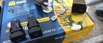
Of course, you can simply replace the contact group with Nexia, but there is no guarantee that the story of contact burnout will not repeat itself. To avoid problems occurring in the future, it is necessary to unload contacts 15 and 30 of the contact group. To do this, it is necessary to install an unloading relay between these contacts. A regular starter relay from a VAZ 2108, connected according to the circuit between pins 15 and 30, is suitable.
New contact group.
Starter relay - 30 A (VAZ-2108) or 50 A (VAZ-2110).
Contact terminals.
Let's understand the connection diagram: you can relieve not only the ignition circuit (pins 30 and 15), but also the starter circuit (pins 30 and 50).
We connect the wires to the terminal block.
We get to the ignition switch by removing the steering column covers.
We assemble an electrical circuit.
Checking the battery
Another reason for a non-working starter is a discharged battery or oxidized contacts at its terminals.
We check the condition of the battery, contact terminals and wires.
If a situation arises when the starter does not turn, check the voltage at the battery terminals and, if necessary, charge it. In addition, it is useful to check the contact density on the positive terminal of the starter itself. The battery terminals are cleaned and lubricated with conductive lubricant, the contact of the positive wire is cleaned and tightened tightly. This way you can avoid problems with starting the engine in the future. Instant launches and sunny roads to everyone!
relays and fuses
The contact group is the cause of starter failure. But perhaps the most common cause of starter failure is the failure of the contact group. If the starter works by itself, as the first test showed, then with a high degree of probability the fault can be caused by the contact group of the ignition switch.
The starter drives on the Daewoo NEXIA, what's the problem?
The fact is that when designing the electrical circuit, the engineers did not take into account the high load on the ignition switch contacts. When starting the engine, voltage from the battery is supplied directly to the contact group and when the starter is turned on, a large current passes through the contacts, they heat up and burn out over time.
Paid links
How to prevent the contact group from breaking down Of course, you can simply replace the contact group on Nexia, but there is no guarantee that the story of contact burnout will not repeat itself.
To avoid problems occurring in the future, it is necessary to unload contacts 15 and 30 of the contact group.
To do this, it is necessary to install an unloading relay between these contacts. A regular starter relay from a VAZ will do, connected according to the diagram between pins 15 and Let's understand the connection diagram: Connect the wires to the terminal block. We get to the ignition switch by removing the steering column covers.
How to remove the starter on a Daewoo Nexia
Renault Megane 2 phase 2,1. So if you do not have the relevant experience, in the event of a breakdown, you can safely contact specialized auto repair shops, where they will quickly and inexpensively solve a similar problem. Where is the cabin filter located on the Kia Sportage? Kia Sportage - Where is the cabin filter located?
And how to replace the cabin filter on a Kia Sportage.
How to find a cabin filter on a Kia Sportage? How to Remove the Kia Spectra Starter How to Remove the Kia Spectra Starter Kia Spectra Removal Installation Disassembling the Starter The starter is located on the clutch housing on the rear side of the power unit.
Visit my channel: The video shows the repair of a burnt contact group of the starter solenoid relay. You can also read about how to repair where the starter is located on a daewoo nexia starter relay with your own hands at the link - http: Later it turned out that the friction plates had come off the brake pads, and the brake cylinder was also jammed.
In order to somehow loosen the brake mechanism and remove the drum, I had to cut off the parking brake cable! After which, we still managed to knock down the brake drum without breaking it into pieces. The drum has somehow become unusable! Where is the starter located on the daewoo nexia, I had to remove the entire brake mechanism and turn off the brake cylinder, unscrew the line from it and put a small piece of rubber in the cylinder and screw the line back on!
This method allows you to temporarily use the car without losing brake fluid in order to get to the repair site.
As a result of the completion of the repair work, the following were replaced: In this case, the throttle system or idle air control of the Daewoo Nexia may be clogged. Otherwise, you need to check the spark plugs and armor wires.
We will be glad to see your likes and comments Subscribe to the channel Our group: The starter is turned on, but the armature does not rotate and the flywheel does not work? The problem can be solved by replacing the clutch, drive or flywheel, depending on the breakdown. If it seems that when you turn on the starter where the starter is located on the daewoo nexia there is excessive noise, then perhaps the whole reason is excessive wear of the bearings, which will only need to be changed.
It is possible that only the teeth of the drive gear or flywheel are damaged; replacement will suffice.
Location and electrical diagram
The diagram of all electrical equipment in Daewoo Nexia cars 8 valves in the body of N100 and N150 1997, 1998, 2004, 2005, 2006, 2007, 2008, 2010, 2011 and 2012 is powered by a 12-volt battery. Connecting devices and devices in these cars follows the same principle. The negative terminals of electrical equipment are connected to ground, that is, to ground or the car body.
The devices are powered from two voltage sources:
- From the battery if the engine is not running and the ignition is on. Activation of the latter is not necessary if the equipment is connected to the battery not through the ignition switch, but directly.
- From the generator unit when the engine is running. When the power unit is started, the generator also recharges the battery, which allows you to replenish the previously used battery charge.
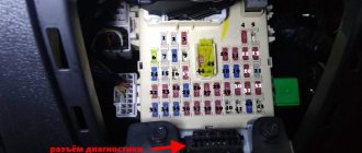
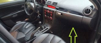
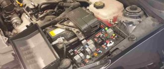
As for the location, in Daewoo Nexia 100 and 150 2005 and other years of production, the fuse box is installed in the lower part of the center console. It can be seen to the left of the control panel. Regardless of the year of manufacture and the body in which the vehicle is made, the position and placement of the mounting blocks, as well as their characteristics and the purpose of the parts are the same. The only difference lies in gaining access to these devices due to some design features of the center console.
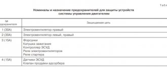
Explanation of fuses
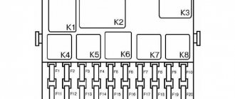
Fuse installation diagram
Let's move on to a description of safety components.
| # | Purpose |
| F1 | Designed to protect the electrical circuits of the control module. This part is considered one of the main ones, since the protection of the power unit control unit is assigned to it. If it burns out, problems with starting the engine may occur; the ECM system will not be able to fully perform all the functions assigned to it. |
| F2 | Protecting the circuits of the side light system in the car |
| F3 | The reserve element can be used when installing additional devices and equipment |
| F4 | Protects electrical circuits of high beam optics |
| F5 | Used to provide protection for the low beam optics, as well as the electric control for the left headlamp. If it breaks, the corrector will not work |
| F6 | This fuse also protects the low beam lighting in the car. He is responsible for the operation of the electric control of the right headlight |
| F7 | Fuel pump fuse. A malfunction of this part will lead to difficulties in starting the engine, and starting the engine will be impossible. Part replacement is required to ensure normal operation of the unit. In addition to the fuel pump, the fuse is used to protect the electrical circuits of the injectors |
| F8 | Safety device f8 protects the turn signal and brake light circuits. The failure of the part will result in the driver not being able to warn other motorists about the maneuver he plans to perform, which can lead to an emergency situation. It will not be possible to activate the light alarm. Driving a car with broken brake lights is dangerous. |
| F9 | The electrical circuits of the windshield cleaning and washing systems are assigned to this fuse. If the part breaks, the driver will not be able to supply water from the expansion tank to the glass, as well as activate the wiper blades |
| F10 | Used to protect the electrical wiring of the fuel filler cap |
| F11 | Ensures the functionality of the air conditioner compressor relay. Installed only on vehicles equipped with an air conditioning system |
| F12 | This fuse protects the electric cooling fan. Failure of a part can lead to overheating of the power unit, since the operation of the fan will be disrupted |
| F13 | Fuse f13 is used to protect several components of the electrical circuit at once. We are talking about the dashboard, digital clock in the center console, cigarette lighter, buzzer. The device also protects the circuits of the reversing headlights, which are activated when the corresponding gear is engaged, the generator unit, as well as the rear window heating system. Failure of a part will lead to the failure of a piece of electrical equipment immediately. The performance of the generator is especially important for the circuit. |
| F14 | This part protects the circuits of the steering horn and the electric fan of the cooling system. We are talking about an increased speed device, which is activated in case of emergency overheating of the internal combustion engine. |
| F15 | Used to ensure the functionality of lighting sources in the cabin and luggage compartment, as well as the electric drive of the antenna |
| F16 | This fuse protects the wiring through which the power windows are connected to the battery. If these elements are manual, then the nest remains free |
| F17 | Protection of the audio system connected through the ignition switch. Failure of a part will result in the inability to use the radio. |
| F18 | This component also protects the audio system only if it is connected directly to the battery. In addition, the fuse protects the rear window heating system, central locking and tailgate opener. |
| F19 | Overvoltage protection of the circuit section responsible for the operation of the stove |
| F20 | Anti-fog optics |
User Denis West in his video talked about how to solve the problem in Nexia if the backlight on the instrument panel has gone out.
Relay type and purpose
In Daewoo Nexia 8 and 16 valves, there are also relays in the safety block. Read about their purpose below.
| № | Purpose |
| K1 | Power unit cooling system fan. This element, like fuse f14, helps prevent failure of the ventilation device. Otherwise, the motor may overheat |
| K2 | This relay is assigned to protect the light sources installed in the headlights. If the turn signal is broken, it will be impossible to operate, as will the light alarm. |
| K3 | Used to protect the electrical circuit section of the fuel pump. If the engine cannot be started, the battery is charged and the starter turns normally, you need to check the functionality of the part |
| K4 | This relay is assigned to protect the front and rear fog lights. |
| K5 | Side lights and fog lights |
| K6 | The electrical circuits of the headlight lighting sources are attached to this part. Operation of low and high beam headlights is possible only if this relay is operational |
| K7 | Also responsible for the operation of the cooling system ventilation device. Relay failure will lead to overheating of the power unit |
| K8 | Air conditioning compressor clutch. If problems appear in the operation of the air conditioning system, the unit does not effectively cool the interior of the car or does not turn on at all, you need to check the functionality of the K8 relay |
| K9 | Responsible for the functionality of the horn |
| K10 | The part is assigned to protect the light sources of the headlights |
| K11 | Used to protect against overvoltage the section of the circuit to which the device emitting a melodic signal is connected. We are talking about sounds that indicate the optics are on when the doors are opened and seat belts are not fastened. Not all units are equipped with such a relay, only the corresponding configuration |
| K12 | The part is secured with protection for the fourth speed of the stove ventilation device. A failure of the relay will lead to the fact that in severe frost the heating system will not be able to properly warm up the interior of the car. |
| K13 | Responsible for the functioning of the ignition system. If the device breaks down, you will not be able to start the engine. |
| K14 | This relay is assigned to protect the electrical circuits of the windshield cleaning system. If the wiper blades and washer system are damaged, they will not work. |
| K15 | Responsible for the functionality of the rear window defroster timer |
Difference between Nexia N100 and N150
There are no differences in the fuse blocks in cars with N100 and N150 bodies. All elements in the devices are located absolutely identically and have the same purpose.
User Expert R spoke in his video about how to solve the problem with safety devices if the cooling fan does not turn on.
Repair
Daewoo Nexia is equipped with electrical equipment operating on direct current with a nominal voltage of 12 volts. Therefore, all devices are connected according to the same principle, and understanding the unit is quite simple.
This is interesting: How to make a car lift for a garage with your own hands? 2 easy-to-use devices
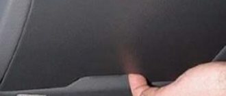
In any case, you first need to find the device itself. The Daewoo Nexia fuse box is located inside the car. Regardless of the year of manufacture, its construction principle and location are identical. However, dismantling may vary due to some structural changes. To access the safety block, you need to disassemble the left side of the panel. The device is designated by the markings “N100” and “N150”.
After dismantling and checking for malfunctions some fuses, it is necessary to replace them. In this case, it is worth considering some features, or rather:
- A fuse cannot be used with a higher current rating than specified by the manufacturer. Otherwise, if there is a short circuit or failure of the electrical circuit, the risk of fire increases many times over.
- The element is replaced with the same one. It is prohibited to use fuses from other vehicles.
- All repairs are carried out carefully so as not to damage the structure of the device.
Important! Repair of the Daewoo Nexia unit can only be carried out with the ignition off, the engine turned off and the battery terminals disconnected. If the installed fuse blows again, then the problem lies either in its electrical circuit or in the unit itself
Only by eliminating such “side” faults can the normal functioning of individual elements and the device as a whole be achieved. It is extremely important not to solve such breakdowns using any “old-fashioned” or “handicraft” methods (replacement with wire, for example), since such things are unacceptable for repairing electrical appliances. By doing something like this, you personally increase the risk of your car catching fire
If the installed fuse blows again, then the problem lies either in its electrical circuit or in the unit itself. Only by eliminating such “side” faults can the normal functioning of individual elements and the device as a whole be achieved
It is extremely important not to solve such breakdowns using any “old-fashioned” or “handicraft” methods (replacement with wire, for example), since such things are unacceptable for repairing electrical appliances. By doing something like this, you personally increase the risk of your car catching fire
Car starter design
Every car owner should know the design of the mechanisms and components of his vehicle. If you understand the operation of the mechanism, you can easily and quickly identify the breakdown and fix it.
Main components of the unit:
- electric motor,
- anchor,
- brushes,
- overrunning clutch.
Some car models may have differences in structure. This should not be taken as a deviation; this happens often. If you are purchasing a part, you must inform the seller about the model of the part that was previously used. If you select the element incorrectly, difficulties may arise with its operation, and it will quickly fail.
If the starter does not respond to the rotation of the key and is in silent mode, then the check is divided into the following stages:
- The battery charge level is detected.
- The ignition switch contacts are being checked.
- The traction relay is being diagnosed.
- The operation of the part of the starter responsible for torsion of the clutch and the mechanism itself are checked.
Possible causes of fuel pump malfunction
Mechanical fuel pump disassembled
A mechanical fuel pump may fail for the following reasons:
- If the integrity of the diaphragm is damaged.
- After dirt accumulates under the valves.
- When the filter is clogged.
- When the spring loses its elasticity.
- If the seal of the housing is broken.
- Due to natural wear and tear of parts during operation.
The electric fuel pump of a modern car is quite reliable. Malfunctions in it arise only due to the influence of certain factors, among which the most common are the following:
Burnt contacts inside the fuel pump
1. Faulty wiring in the form of dirty, rusty, melted or damaged wires in the fuel complex interferes with the operation of the device and also limits the required current parameters, making it difficult to pump fuel.
2. Debris and foreign impurities in the fuel tank in the form of rust, dirt, water, mechanical particles that penetrate the fuel pump and cause its breakdown.
Location and electrical diagram
The Nexia uses DC electrical equipment with a nominal voltage of 12 volts. All energy consumers in a given vehicle are connected according to the same principle. In particular, the negative terminals of the equipment are connected by ground (that is, connected to the body of the car), which, in turn, acts as a second wire. The power supply for all devices comes from two sources: if the engine is not running, then from the battery (battery), if it is running, then from the generator.
The fuse box (hereinafter referred to as the BP) and relay in the Daewoo Nexia car is located at the bottom of the car’s dashboard. Specifically, it is located on the left side of the instrument panel. In vehicles produced before 2008, the PSU is marked N100, and in younger cars - N150. Let us tell you right away that in terms of their design, circuit and purpose of components, the power supply units are absolutely identical. The only difference is in access to them due to the design features of the torpedo.
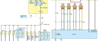
We present to your attention a diagram of the power supply unit and relay with a description of all the elements.
Power supply diagram for Daewoo Nexia cars - it shows the numbers of all components of the unit and relays
Table describing the purpose of mounting block fuses
You may also find the relay description useful.
| Detail number | Purpose |
| K1 | This relay is responsible for the operation of the ventilation device of the cooling system. Specifically, this relay is called a “high fan speed relay.” |
| K2 | This element ensures the functioning of the direction indicator lamps. Accordingly, if it fails, you will not be able to signal to other drivers about your intention to turn. |
| short circuit | Responds to the functioning of the fuel pump. If this relay fails, the operation of the fuel pump will be impossible and, accordingly, it will not be possible to start the engine. |
| K4 | Responsible for the operation of the front and rear fog lights. |
| K5 | Provides operation of side lamps and fog lamps. |
| K6 | If this relay breaks down, the operation of the headlight lamps (responsible for low and high beam) will be impossible. |
| K7 | The failure of this component, which is responsible for the speed of the cooling system fan, indicates that the engine may overheat and, as a result, boil. This part must be replaced immediately if it fails. |
| K8 | A breakdown of this relay indicates that the climate control system compressor clutch is not working. |
| K9 | Responsible for the operation of the steering wheel horn. |
| K10 | Also ensures the performance of headlight lamps. |
| K11 | This component ensures the functionality of a melodic signal (sound when doors are opened, seat belts are not fastened - depending on the configuration). |
| K12 | The relay is responsible for activating the fourth speed of the heating system fan. If it fails, then at too low temperatures the heater will not be able to operate at full capacity. |
| K13 | The ignition system ensures operation. If the relay burns out, starting the engine will be impossible. |
| K14 | Responsible for the windshield wiper device. |
| K15 | Rear window heating timer. |
Signs of a fuel pump malfunction
Mechanical fuel pumps
In a mechanical fuel pump, malfunctions most often occur due to wear of the sealing gaskets and the formation of leaks between parts of the housing. As a result, the tightness of the structure is broken, air gets in, fuel stops getting into the carburetor and the engine stalls. A similar consequence is caused by membrane rupture and valve failure. At the same time, the car begins to move jerkily until the fuel supply stops completely.
Electric fuel pumps
On cars with mechanical and electronic injection, the signs of a fuel pump malfunction are slightly different, but they can be classified into certain groups:
- The engine does not start. Rotation of the starter with dry spark plugs does not cause flashes in the cylinders. There is no pressure in the fuel line, or it is extremely low; the buzzing of the pump is not heard when the ignition is turned on or the starter is operating.
- The engine does not start, although occasional flashes occur in the cylinders. There is pressure in the fuel line, but without a pressure gauge its value cannot be determined. The candles are dry.
- The engine starts and idles normally, but pressing the accelerator causes it to stop. If you want, it is possible to raise the speed to medium, but attempts to start lead to the engine stalling. There is a black coating on the spark plugs, the operation of the fuel pump is characterized by a changing sound.
- The engine starts, holds idle speed normally, and picks it up easily at neutral speed. When driving at medium and high speeds, a “twitching” is observed. It happens that after a certain mark on the tachometer the speed does not pick up, and the engine stops producing the required power under load. At the same time, the spark plugs are white, and by their appearance it seems that the car is ignited too early or has a lean mixture.
It is worth noting that the above symptoms of fuel pump malfunctions are also typical for other engine breakdowns, and they cannot be used to unambiguously diagnose a fuel pump malfunction. For example, speed also fluctuates if there is a problem with the air sensor, throttle valve, clogged injectors or poor quality fuel.