Modern “tens” are equipped with many different electronic devices and components that perform various functions. One of the important elements is the crankshaft sensor on a VAZ 2110 car. In this article we will talk in detail about the purpose and symptoms of a malfunction of the regulator.
What is a crankshaft position sensor on a vase
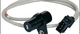
The VAZ 2110 induction type crankshaft sensor is installed next to a special disk located together with the crankshaft drive pulley. The special disk is called a reference or master disk. Together with it, it ensures angular synchronization of the operation of the control unit. Skipping two teeth out of 60 on the disk allows the system to determine the TDC of the 1st or 4th cylinder. The 19th tooth after skipping should face the DPKV rod, and the mark on the camshaft should be against the bent reflector bracket. The gap between the sensor and the top of the disc tooth is in the range of 0.8-1.0 mm. The sensor winding resistance is 880-900 Ohms. To reduce noise levels, the crankshaft sensor conductor is shielded.
After turning on the ignition, the control program of the unit is in the waiting mode for the synchronization pulse signal from the crankshaft position sensor. When the crankshaft rotates, the sync pulse signal arrives instantly to the control unit, which, in accordance with their frequency, switches the electrical circuit of the injectors and the ignition coil channels to ground.
The control unit program algorithm works on the principle of reading 58 teeth passing by the magnetic core of the DPKV, skipping two. The skipping of two teeth is a reference mark for determining the piston of the first (fourth) cylinder in the top dead center position, from which the unit analyzes and distributes the switching signals that control the opening of the injectors and the spark on the spark plugs over the engine operating strokes.
The control unit detects a short-term failure in the synchronization system and tries to resynchronize the control process. If it is impossible to restore the synchronization mode (lack of contact on the DPKV connector, cable break, mechanical damage or broken master disk), the system issues an error signal to the instrument panel, lighting the Check Engine warning lamp. The engine will stall and it will be impossible to start it.
The crankshaft position sensor is a reliable device and rarely fails, but sometimes malfunctions occur due to the inattentive or negligent attitude of specialists servicing the engine.
The crankshaft position sensor is a reliable device and rarely fails, but sometimes malfunctions occur due to the inattentive or negligent attitude of specialists servicing the engine.
For example, a VAZ-2112 has a 21124 engine (16 valves where the DPKV cable is located very close to the exhaust manifold ) and the problem usually arises after repairs, when the chip on the cable is not secured to the bracket. When the cable comes into contact with a hot pipe, it melts, destroying the connection circuit and the car stalls.
Another example could be a poorly manufactured drive disc , the rubber coupling of which can rotate along the internal connection.
The electronic control unit, receiving a single signal from the DPKV, determines the position relative to the crankshaft at each moment of time, calculating its rotation frequency and angular velocity.
Based on sinusoidal signals issued by the crankshaft position sensor, a wide range of problems are solved:
- Determination at a given time of the position of the piston of the first (or fourth) cylinder.
- Control of fuel injection timing and injector open duration.
- Ignition system control.
- Control of variable valve timing system;
- Control of the fuel vapor absorption system;
- Ensuring the operation of other additional systems related to engine speed (for example, electric power steering).
Thus, the DPKV ensures the functioning of the power unit, determining with high accuracy the operation of its two main systems - ignition and fuel injection.
Before purchasing a DPKV to replace it, you need to clarify the type of device installed on the engine.
Functions and purpose of the VAZ 2110 crankshaft sensor
On an engine with 8 or 16 valves, the DPKV is designed to perform not control options, but to implement phase synchronization for gasoline injection. Also, the crankshaft sensor on the VAZ 2110 transmits an impulse to ignite the air-fuel mixture in the combustion chambers of the power unit. Therefore, if the controller breaks down, this can lead to various vehicle systems not functioning coherently. This means that normal operation of the engine will be impossible.
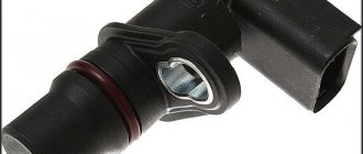
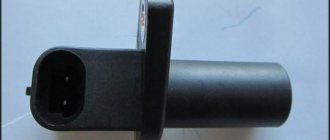
VAZ 2112 crankshaft sensor
The VAZ 2110 crankshaft sensor itself is an inductive type device; this controller must respond to the passage of teeth on the master disk. This disk is mounted on the generator drive pulley, and the controller itself is installed next to it. There are 58 teeth on the pulley, between which there is a cavity the size of 2 teeth. This cavity allows synchronization with the top dead center of the engine pistons. The moment the depression passes the controller, a corresponding signal is sent to the engine control unit.
There are quite a few designs of devices of this type; the principle of their operation is based on a regulator such as the VAZ 2110 Hall sensor. In the latter case, the regulator also responds to a rotating shaft, but its operation is carried out as a result of the passage of a permanent magnet.
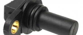
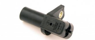
Inductive (magnetic) crankshaft sensor VAZ 2110
The device is based on a magnetized core placed in a coil. At rest, the magnetic field is constant and there is no self-induction emf in its winding. When the top of the metal tooth of the driving disk passes in front of the magnetic core, the magnetic field around the core changes, which leads to the induction of current in the winding. When the disk rotates, an alternating current appears at the output, and the frequency of the current varies depending on the speed of the shaft rotation. The work is based on the effect of electromagnetic induction.
A special feature of this sensor is its simple design, which operates without additional power supply.
Hall effect sensor
The type of these sensors operates on a microcircuit, placed in a housing with a magnetic core, and the drive disk creates a moving magnetic field with magnetized teeth.
The sensor provides high accuracy of signal output in all specified crankshaft rotation modes. A sensor operating on the basis of the Hall effect requires a constant voltage connection.
Optical sensors
It is based on the physical phenomenon of the photoelectric effect. Structurally, it is a light source with a receiver (photodiode). Rotating between the source and the receiver, the perforated disk periodically closes and opens the path to the light source, as a result the photodiode produces a pulse current that arrives in the form of an analog signal to the control unit (the system has limited use and was previously installed in the distributors of injection cars, for example, Matiz).
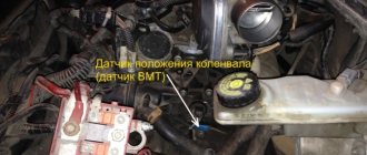
Where is the crankshaft sensor located on the VAZ 2110?
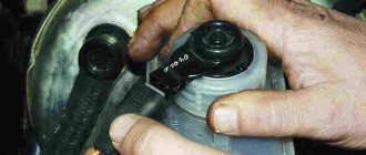
If malfunctions are noticed in the operation of the engine, then before you begin to identify the breakdown and signs of malfunction, you need to find out where the regulator is located. Where is the crankshaft position sensor located on an 8- or 16-valve “ten”? If you open the hood, you will notice that the regulator can be found directly on the oil pump cover. As you can see, the location of the regulator is not particularly convenient. VAZ engineers thought through this point, thinking about the convenience of replacing the controller, so they equipped the DPKV with a long 80 cm wire.
Location of the DPKV under the hood of the car
What cars is the crankshaft position sensor suitable for?
| Model | Engine code | Year | Engine capacity, l. |
| 110 (2110) 1.5 | BA3 2111 / VAZ-2111 | 1995 — 2005 | 1,5 |
| 110 (2110) 1.5 16V | VAZ-2112 | 1995 — 2010 | 1,5 |
| 110 (2110) 2.0 i | C 20 XE | 1996 — 2000 | 2 |
| 110 (2110) Wankel | VAZ-415 | 1997 — 2004 | 2,6 |
| 110 (2110) 1.6 | VAZ-21114 / VAZ-21124 | 1995 — 2012 | 1,6 |
| 110 (2110) 1.6 16V | VAZ-21124 | 2004 — 2010 | 1,6 |
| 110 (2110) 1.6 LPG | VAZ-21114 | 2004 — 2007 | 1,6 |
| 111 (2111) 1.5 | VAZ-2111 / BA3 2111 | 1996 — 2005 | 1,5 |
| 111 (2111) 1.5 16V | VAZ-2112 | 1995 — 2005 | 1,5 |
| 111 (2111) 1.6 | VAZ-21114 / VAZ-21124 | 2004 — 2013 | 1,6 |
| 112 (2112) 1.5 | VAZ-2111 | 1995 — 2005 | 1,5 |
| 112 (2112) 1.5 16V | VAZ-2112 | 1995 — 2005 | 1,5 |
| 112 (2112) 1.6 | VAZ-21124 / VAZ-21114 | 2005 — 2011 | 1,6 |
Features of the VAZ 2112 control unit
The ECU is located under the dashboard console and controls the fuel injection system. Its task is to process information from various sensors, control systems that affect the toxicity of exhaust gases emitted by the car and the performance of the car during operation. Information received by the controller indicates:
Rotation speed and crankshaft position. Engine air mass flow. Oxygen content in the exhaust gases. Coolant temperature. Presence of detonation in the engine. Throttle position. Voltage in the vehicle's on-board network. Vehicle speed. Camshaft position in a sequential fuel injection system. Turn on the air conditioner, if present.
After receiving the information, the VAZ 21124 engine control unit controls the systems and devices:
- Heat dissipation. Controls the operation of injectors and electric fuel pump.
- Ignition system.
- Adsorber for the gasoline vapor recovery system (when installed on a car).
- Engine cooling fan.
- Idle speed regulator.
- Air conditioning compressor clutch.
- Diagnostic system.
The VAZ 21214 engine control unit includes output circuits - injectors, relays and other devices by connecting them to ground through the controller output transistors. The exception is the fuel pump relay circuit. Only the voltage of +12 V is supplied to its winding from the controller. The controller is equipped with a built-in diagnostic system. With its help, he recognizes malfunctions in the operation of devices and systems and warns the driver about them. To do this, a “CHECK ENGINE” warning lamp is installed in the car. In addition, it stores diagnostic codes that indicate areas of failure, which helps technicians make subsequent repairs. The photo shows a diagram of the fuel injection system.
Fuel injection system
In the diagram, position 11 is the controller.
Main devices of the VAZ 2112 engine control unit
The product has three types of memory:
The first RAM or random access memory. This is a kind of “scratchpad” of the controller. It is used by the microprocessor of the control unit for temporary storage of measured parameters to obtain intermediate information and for calculations. The microprocessor can, if necessary, enter data here and then read it. The RAM chip is mounted on the printed circuit board of the unit. This volatile memory is for maintaining uninterruptible power supply.
There are distribution fuel injection systems of this type:
- With feedback. In this case, an oxygen concentration sensor, otherwise called a lambda probe, is installed in the exhaust system; it provides feedback and a neutralizer. In the exhaust gases, the sensor monitors the concentration of oxygen, and the ECU maintains the ratio of fuel and air based on its signals to ensure efficient operation of the converter. In systems that comply with Euro-2 standards, one oxygen sensor is used, installed before the converter. In systems with Euro-3, there are two oxygen sensors mounted: one before, the other after the converter.
- For engines in which the injection system does not have feedback, an oxygen concentration sensor and a neutralizer are not installed, and the CO concentration in the exhaust gases is adjusted by a CO potentiometer. In this system, a system that provides fuel vapor recovery is also not used.
- It is possible that the injection system does not have a CO potentiometer, then the CO content is adjusted using a diagnostic tool.
- There are phased and sequential distributed fuel injection systems. In the first case, distributed injection has a VAZ 2112 engine control unit with 16 valves. It is additionally mounted with a phase sensor, which determines the moment when the compression stroke in the 1st cylinder ends, and fuel is supplied by injectors to the cylinders in the same sequence as the ignition in the cylinders is turned on (1-3-4-2).
Features of injection systems
The injection system operates thanks to a sensor system and a control unit. All signals are input to the microprocessor unit, which regulates the operation of the actuators. The following sensors are responsible for the correct operation of the engine:
- Crankshaft positions.
- Camshaft positions (not on all versions).
- Intake manifold pressure.
- Lambda probe.
- Speed.
- Mass air flow.
- Throttle position.
And the main role is played by the VAZ-2110 crankshaft sensor (8 valves or 16), since the moment of injection and supply of high voltage to the spark plug electrodes depends on it. The design has a temperature sensor, but it has virtually no effect on operation. It is necessary to control the engine temperature and send a signal to the dial indicator (or to the on-board computer). But it will be indispensable if it is necessary to implement automatic switching of fuel types (from gasoline to gas and back).
Algorithm of operation of the injection system
The microprocessor has several inputs and outputs. The inputs receive signals from all sensors. But first, these signals are converted and, if necessary, amplified. The microcontroller is programmed to work with sensors and actuators. Programs (firmware) can provide various engine characteristics.
You can achieve an increase in power (gasoline consumption will increase) or a decrease in consumption (power will suffer). But most motorists prefer programs that provide work with average parameters. In this case, the signal from the VAZ-2110 crankshaft position sensor does not change; only the reaction of the actuators to changes in input data is adjusted.
Air flow control
The location of the mass air flow sensor (MAF) is on the air duct running from the filter to the throttle valve. The device consists of 3 elements located inside the air flow. The first one measures the temperature of the incoming stream, and the other 2 heat up to a certain degree. The stronger the flow passing through the air sensors of the VAZ-2110, the more intensely they are cooled. The controller that supplies the voltage determines the air flow by the energy spent on heating the 2 elements in relation to the temperature of the first meter.
There is another design of the MAF device with a silicon mesh and two elements; it operates on the same principle. The marking of the first type is 2112-1130010, the second - 21083-1130010. Receiving signals from these devices, the processor makes a calculation and changes the duration of fuel injection for the VAZ-2110. The following signs indicate a sensor failure:
- the engine stalls when switching from high speed to idle;
- unstable operation at idle;
- difficulties arise when starting the engine;
- increased fuel consumption.
Replacing the mass air flow sensor control device is not difficult; you need to disconnect the wires, remove the old sensor from the air duct and install a new one.
A little about the crankshaft
The crankshaft is the most important element of any internal combustion engine. It is driven by the starter (at the moment of starting) and the pistons (in operating mode). From it, torque is transmitted to the gearbox, gas distribution system, and auxiliary mechanisms. And in order for fuel injection to be carried out in a timely manner, a spark to form at the right moment, a VAZ-2110 crankshaft sensor is needed.
It monitors the position of the pulley and transmits a signal to the electronic control unit. The pulley has teeth, the distance between them is the same. But in one place there is a gap - two teeth are missing. The position sensor reacts to the approach of metal. When an empty area passes near the sensor, a signal is generated - the control unit is notified that one revolution of the crankshaft has occurred.
Purpose and principle of operation of the sensor
On 8- and 16-valve engines, the VAZ 2110 knock sensor performs the function of controlling the combustible mixture ignition system. Due to late ignition, the driver may encounter problems with increased gasoline consumption, decreased engine power, and overheating. If the ignition of the combustible mixture is delayed, this can lead to burnout of the valves and also a decrease in engine power.
As for the principle of operation of the device on an internal combustion engine with 8 or 16 valves, it consists of the piezo effect. That is, the voltage level depends entirely on the physical impact on the component. If the pressure is higher, the voltage pulse will increase accordingly.
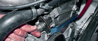
Removing the regulator from its installation location
Replacing chips and pinout of DPKV VAZ 2110
Over time, the wires going to the DPKV chip wear out. Located in the lower part of the engine and not far from the front wheel, as a result, dirt, snow, oil, and aggressive chemical media in the form of salt get on the DPKV and its chip and settle, which leads to slow oxidation of the wires on the chip and subsequently to their breakage. Since the wires from the chip are combined into a single bundle, when replacing it, a repair chip is provided with protruding two wires 15 cm long. Having removed the damaged chip, install a new one with a twist. The twist points are insulated using heat shrink or electrical tape.
From the diagram below it can be seen that their pinout is not complicated and two wires are directly connected to the signal input contacts in the control unit, passing along the entire length of the harness. The polarity of the connection between the signal wires of the sensor and the control unit must be observed. If the polarity is reversed, the synchronization system will not work. To restore the operation of the DPKV, you simply need to swap the wires and check the functionality by starting the engine.
Device and classification
Despite the fact that the VAZ crankshaft sensor may have a different design, its operating principle is based on a single electromagnetic effect. That is, the signal is generated without direct contact with the crankshaft.
The most common type of DPKV is induction. Such a part consists of two main elements - a magnetized rod and a special winding. Induction sensors read information from the crankshaft toothed pulley. When a metal tooth passes near the DPKV, an EMF is formed in the latter, which is captured by the electronics. On the VAZ-2110, the crankshaft sensor is installed of the induction type.
DPKV can also be based on the Hall effect. Such a sensor is constructed in approximately the same way as an induction sensor, however, when a metal shaft passes near it in the winding of the device, the resistance changes. Structurally, it consists of a permanent magnet.
It should be noted that both the first and second types of sensors are used to read data from the crankshaft pulley. It can be toothed or all-metal. In the latter version, there is a special recess that passes by the sensor and generates a signal that is sent to the vehicle’s electronic engine control unit.
Signs of breakdown
Any malfunction of the VAZ 2110 crankshaft sensor will cause the engine to be unable to start after a long period of parking. If the controller starts to malfunction while operating the car, in 90% of cases the engine will stall, since the ECU will not generate a signal to the ignition system, and the internal combustion engine safety function will work. Signs of a sensor malfunction when the unit begins to break down:
- Check Engine is activated on the dashboard;
- engine speed becomes unstable, traction decreases by 50%;
- The VAZ 2110 crankshaft sensor must be urgently changed if the following sign of a malfunction appears: when the speed increases, a hum is felt in the engine area and knocking;
- An injection engine is characterized by the appearance of popping noises in the exhaust tract area.
When the VAZ 2110 dpkv is completely faulty, the engine stalls because the computer does not send signals to form a spark.
These symptoms do not always indicate that a complete replacement of the VAZ 2110 crankshaft sensor is necessary, since all faults of the element are conditionally divided into four groups:
- surface clogging;
- damage to the winding of the device and violation of its integrity;
- manufacturing defects;
- open circuit or short circuit in the circuit.
Checking the sensor begins with cleaning the part. The cleanliness of the contacts, their security, the cleanliness of the connector are checked, and oil stains are eliminated. The design of the sensor is quite simple, but 20 percent of device failures are factory defects. The wiring break is repaired after ringing the circuit. The VAZ 2110 crankshaft sensor is not repaired, since the cost of the consumable does not exceed 100 rubles; the unit is replaced with a similar one after a short diagnosis.
Reasons for failure of the DPKV
In order to ensure the longest possible operation of the new part after replacing the sensor, you need to know about the reasons that most often cause failure of the DPKV.
This category of vehicle states and operating modes includes:
- Mechanical damage.
- Dirt, sand or metal shavings get inside.
- DPKV breakage due to crankshaft teeth.
- Short circuits in the car's electrical wiring.
In addition to the reasons listed, the sensor may not work due to manufacturing defects or errors during repair and installation operations.
Crankshaft sensor VAZ 2110 Causes of failure
There are a small number of reasons why a sensor may fail, but they still exist.
- Mechanical damage;
- Aging;
- Electrical damage;
- Open circuit control;
Let's consider each of the breakdown options in more detail.
Mechanical damage. May be caused by any impact to the sensor. For example, when trying to dismantle the sensor, similar breakdowns are possible.
Aging. Often on older cars the sensor may fail due to its aging and demagnetization of the core.
Electrical damage. With such a breakdown, the coil inside the sensor most often breaks, and it stops sending a signal to the ECU.
Open circuit control. A break in the control circuit does not refer to a sensor failure. If there is a break, the wiring that transmits the signal from the sensor to the ECU is affected.
Tips and tricks
In the process of performing diagnostic and repair work, an inexperienced technician may make serious mistakes that will negatively affect both the performance of the part itself and other devices and assemblies of the machine. To protect yourself from such troubles, it is recommended to adhere to the following recommendations:
- When performing repair work, you should stop smoking. When removing the sensor, a certain amount of lubricating fluid may appear, which is a highly flammable substance.
- When measuring resistance, the multimeter must be switched to the appropriate operating mode. Some modes that can be used to determine this parameter of an electrical circuit are also not suitable. For example, when the toggle switch is set to a resistance measurement range of up to 200 Ohms, the nominal value of DPKV (500–700 Ohms) will be outside its limits, which will lead to false positive results in determining the malfunction of this part.
- If the DPKV fails due to severe contamination, then the new part may also not last very long. To significantly increase the service life of the DPKV, it is recommended to eliminate oil leaks, which can cover all parts within a short period of time. This film, like a magnet, attracts dust and dirt.
- You should only purchase a new part from a reputable dealer. Failure of the DPKV due to manufacturing defects is a fairly common reason if the sensor is purchased on specialized markets. An indirect sign of a low-quality spare part is its cost. Typically, counterfeit spare parts are sold 2-3 times cheaper compared to original products.
- When replacing a sensor, the wires must be properly connected to it. If this is not done, the connector may become separated from the contacts when driving on a bumpy road, which will lead to the cessation of impulses from the DPKV to the vehicle's ECU.
How to check the crankshaft sensor of a VAZ 2112 is described in detail in this article. If you fix the breakdown strictly according to the instructions, then even an inexperienced person can handle this work. If you have doubts about your own abilities, you should not risk the “health” of the car. The work of replacing the DPKV is carried out by many specialized service stations, is relatively inexpensive and does not require significant time expenditure.
Checking the VAZ 2110 crankshaft sensor for serviceability
To verify the suspicion of a breakdown of the crankshaft sensor, the two most likely cases of its malfunction are considered. In both of these cases, you will need to dismantle the device using a ten-threaded wrench. Before the operation, marks are drawn on the crankcase and the sensor itself, which will later help to tighten the device to the initial angle of rotation.
Also, the motorist should not forget to measure the clearance between the synchro disk and the sensor before dismantling, which cannot go beyond the size of 0.6-1.5 mm. If there are no mechanical damage such as scratches, dents, or damage to the material structure, the sensor is checked using other measuring instruments:
- checking with an ohmmeter. In this case, it is necessary to measure the resistance of the sensor winding. Since the standard value of this indicator, set by the manufacturer, ranges from 550 to 750 Ohms, going beyond the specified limits indicates the malfunction of this device, which is important for the correct operation of the car - which means it is faulty. It is worth noting here that the manufacturer still allows a slight discrepancy in resistance with the nameplate values, but in any case they must correspond to the data specified in the machine’s operating instructions;
- checking with a voltmeter, inductance meter and transformer. This method is more complicated, but more effective - the resistance is measured with the same ohmmeter, after which the inductance is checked (should be from 200 to 4000 millihenry), with a sensor winding voltage of 500 Volts. Next, you need to measure the resistance with a megger and make sure that it does not exceed 20 MOhm.
If the sensor still does not pass these tests, it must be replaced. During this procedure, it is necessary not to forget about the distance between it and the synchronization disk regulated by the manufacturer, as well as alignment with the marks on the crankcase that were made on the previous device. Before installing a new sensor, be sure to check it, since even if all installation procedures are followed correctly, it may not work properly.
A new DPKV is checked according to the same procedure as a supposedly faulty one, and based on the test results, the device can be installed instead of the previous one or rejected. When installing, the bolts are tightened with a torque of 8 to 12 Nm. However, in any case, before carrying out all the actions to replace a rather expensive and hard-to-reach component, you should definitely make sure that it is the one that has failed, because cars produced by our automotive industry can often bring unpleasant surprises.
The first way to check the crankshaft sensor VAZ 2110
In this case, you will need an ohmmeter , which you will use to replace the resistance on the winding. According to the manufacturer's standards, the indicator ranges from 550 to 750 Ohms.
It's okay if your numbers are slightly different from the norm. If the deviations are serious, you will definitely have to replace the sensor.
It should be noted in fairness that the crankshaft position sensor on VAZ 2110 models rarely breaks down. Among the main reasons for its failure to function normally is the accumulation of dirt, mechanical damage, as well as banal factory defects.
Features of testing on other cars
As for other cars, for example, VAZ-2109 with an injection engine, VAZ-2112 and VAZ-2114, their check is carried out identically to the VAZ-2110 car.
It is noteworthy that for VAZs, when checking the resistance of the crankshaft sensor coil, an additional check can be carried out.
But to do this, the multimeter must be switched to voltmeter mode with a measurement limit of 200 mV.
Then connect the probes to the DPKV terminals and pass them with any metal object, for example, a screwdriver, at a short distance from the core.
If the sensor is working properly, it will react to metal, the multimeter will show voltage surges on the display. The absence of these bursts will indicate a faulty element.
As for a car like the Reno Logan, the difference from the VAZ in this car comes down to slightly different readings of the resistance of the sensor coil when measured with an ohmmeter.
A working Logan DPKV has a normal resistance of 200-270 Ohms.
For Daewoo Lanos, the coil resistance should be in the range of 500-600 Ohms.
But on the ZMZ-406 engine, installed on Volga and Gazelle cars, the normal coil resistance is in the range of 850-900 Ohms.
Second method
Here you will need a voltmeter, a transformer and an inductance meter. It is advisable to measure resistance under compact temperature conditions.
Once the ohmmeter readings are obtained, arm yourself with an inductance measuring device. Normally, the device should show from 200 to 4000 units (millihenry).
A megger measures the resistance when the crankshaft position sensor winding is powered at 500 volts. Under normal conditions, the readings will be no more than 20 MΩ.
Functionality check
If you decide to check the serviceability of the sensor yourself, treat this procedure responsibly and carry it out correctly. On a VAZ 2114 car, the crankshaft sensor is checked in several ways.
- Using a multimeter. The serviceability of the induction sensor can be assessed by the resistance of its coil. In a working product it is 500-700 Ohms.
- On the multimeter, set the measurement limit to 200 millivolts, connect the probes to the terminals (where the standard wires are connected). Pass a steel object several times in front of the core. The working sensor will “see” the metal and there will be voltage spikes on the multimeter display. If there are none, replace the part.
- But the most accurate results when checking are provided by an oscilloscope. When using this device, one hundred percent results can be guaranteed; it reads all the information from the sensor while the engine is running. It can be observed on the device screen. The engine, during tests, should operate at different speeds. They start with eight hundred revolutions, then two thousand, and raise it to six thousand. If the lines (on the device screen) are of different lengths, you need to look for the cause of the malfunction. Remove dirt, check the pulley for defects, and so on.
Oscillogram of a working sensor
Oscillogram of a working VAZ 2114 crankshaft sensor
It should be noted that these verification methods work on all VAZ models with DPKV. If you have any doubts about your own abilities, then contact the service. Thanks to specialized equipment, the result will be more accurate, and the check will not take much time.
Remove from the engine
The malfunction has been identified. Let's start eliminating it. Let's look at this operation using the VAZ 2114 as an example.
Turn off the car ignition. We open the hood, fix it firmly, and visually determine where the VAZ 2114 crankshaft sensor is located. Before removal, it is advisable to remove all contaminants in the area where it is located. Next, carefully remove the block with wires from the connector.
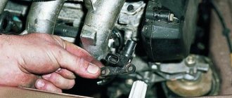
Using a “10” wrench, unscrew the fastening bolt.
Removing the crankshaft sensor on a VAZ 2114
After dismantling the sensor, it is advisable to check the generator drive toothed pulley for defects. Since its damage can introduce errors into the operation of the entire system.
After we are convinced that there are no defects of any kind, we proceed to assembly. The seat must be clean. We install the new part in place and fasten it with a bolt (the tightening torque should not exceed 8-12 Newton meters). In this case we use adjusting washers. They are sold complete with a new sensor. Thus, using a special probe, we ensure that the gap between the pulley and the sensor core is one millimeter. The permissible error is 0.41 millimeters in the larger direction.
The gap between the pulley and the crankshaft sensor core on a VAZ 2114
We connect the block with wires into place.
After installation and checking the gap, we try to start the engine. With a confident start and stable operation of the engine, we can say that the repair was carried out successfully.
Despite the fact that the breakdown of the synchronizing sensor is not frequent, knowledge of its symptoms and consequences, as well as methods of elimination, will be useful to the car enthusiast.
New sensors are available in almost any auto parts store. The price of DPKV can vary between 200-400 rubles. How much a VAZ 2114 crankshaft sensor costs depends on your region, the location of large spare parts stores nearby (usually cheaper there) and the greed of the seller. Can be ordered in the online store. When purchasing, take the old one with you so as not to make a mistake in choosing a model. To avoid defects and repeated purchases, it is advisable to purchase from well-established sellers.
The crankshaft or crankshaft position sensor is an electromagnetic device that transmits data about the current position of the crankshaft to the electronic engine control unit. It is difficult to overestimate the importance of this device, since the correct operation of the injectors responsible for supplying fuel, as well as the entire ignition system as a whole, depends on its performance.
Controller diagnostics
Diagnostics of the crankshaft position sensor is carried out on the dismantled controller. It is recommended to set a timing mark on the crankcase before removing it so that when installing a new element, the correct gap between the tracking device and the timing disk will be maintained. The permissible gap is 0.6–1.5 mm.
We remove the element with a 10mm wrench and carry out a visual inspection. Before checking the crankshaft sensor, the battery is disconnected and the contact points are checked. During a visual inspection, the integrity of the housing, wires, connectors, and the absence of cracks and dents on the housing are checked. If there are no signs of mechanical damage, the DPKV is checked with a multimeter.
Testing of the node can be carried out both by resistance and voltage parameters. Testing for resistance is much simpler, so it is used in most diagnostic options.
The resistance on the working controller winding should be in the range of 550–750 Ohms. Measurements are taken on two contacts of the part. For a 16-valve injector engine, a resistance deviation of 5% is considered acceptable.
Drivers rarely use the second testing option, although diagnostics with a voltmeter are considered more reliable. To check, you will need a transformer and an inductance meter, for example, the MY-6243 multimeter model is often used to measure capacitance and inductance. Checking step by step.
- Calculate the inductance dpkv. The working element at a voltage of at least 500 mV will show an inductance in the range of 200–4000 iH.
- Check the resistance; a working sensor shows a parameter of 20 mOhm.
Functionality check
Don't rush to conclusions. You shouldn’t blame DPKV for all the troubles. Sometimes it turns out that the cause of the problem is completely different. Therefore, first you should check whether your DC is working or not.
There are several ways to check.
- Multimeter. Your task is to measure the coil resistance on the induction sensor. If it is working properly, then the indicator will be from 500 to 700 Ohms.
Multifunctional multimeter
- Set the measurement limit on the multimeter to 200 millivolts, connect the probes to the output and pass a metal object around the core several times. If the sensor is working, it will be able to detect this metal and a voltage spike will appear on the display. If there are no surges, the DC must be replaced.
- An oscilloscope. This verification method gives the most objective and accurate result, equal to almost 100%. Connect the device to the engine and read data in different modes. The engine will need to be started at different speeds - from 800 and above, up to 6 thousand. Look at the lines appearing on the screen. If they are of different lengths, you should look for the reason for the malfunction. Sometimes simple cleaning of dirt, checking the pulley for damage and other measures helps.
To change or not to change the crankshaft sensor of the VAZ 2110?
Let’s make a reservation right away: before deciding that the DPKV needs replacement, you need to check:
- Condition of the wiring going to the DPKV;
- Availability of high-quality contacts in the circuit;
- No damage to wire insulation;
- No oil on the crankshaft position sensor. Since the oil pump is located next to the DPKV, oil leakage can also cause its malfunction.
Functional crankshaft position sensor
If you have already examined everything, you need to check the sensor itself. But to do this you need to remove it.
Replacement
If signs of a malfunction of the DPKV are associated with damage to the device, it is replaced without repair. The controllers are located in an inconvenient place; they are attached to the oil pump cover with a single bolt. How to remove an element step by step.
- The ignition is turned off, the negative terminal of the battery is removed.
- The oil pump where the sensor is located is determined, and the connector is removed. There is an 80 cm wire from the controller to the block; you can determine the location of the connector by the wire.
- Use a 10mm wrench to unscrew the only screw.
- The device is removed.
Before installing a new element, you must thoroughly clean the sensor seat and connector plug, and check the integrity of the wiring. This will avoid rapid failure of the new part.
If the problem in the operation of the internal combustion engine is due to the lack of a signal from the sensor connector on the computer, check the integrity of the wiring. Electronics diagnostics, if there is a signal but no response from the electronic unit, are carried out in a specialized workshop. In 90% of cases, flashing of the control system and replacement of electronic components is required.
In half of the cases, the sensor fails due to simple dirt. The controller is located in close proximity to the oil pump, which can throw out drops of liquid. Oil getting on the sensor reading element clogs the surface, oxidizes and interferes with the full transmission of data.
Dismantling and installation
So, you have determined that the DPKV has failed. Therefore, there is nothing left to do but replace it. To do this you will have to dismantle the old device.
- Turn off the ignition and open the hood. Securely secure it to avoid unpleasant blows to the back or head.
- Remove any dirt from around the sensor so that it can be removed and visually inspected.
- Disconnect the wiring block from the corresponding connector.
- Using a 10 mm wrench, you can easily remove the crankshaft sensor mount.
- Remove the damaged device.
- At the same time, be sure to check the generator drive timing pulley. It is not uncommon for damage to appear on it, due to which the device cannot operate correctly. These teeth cause error codes to appear on the on-board computer.
- If there are no defects and nothing prevents the installation of a new device, begin assembly.
- If necessary, clean the installation site of the DPKV.
- Place the new measuring device in the socket and tighten the mounting bolt. In this case, do not exceed a tightening torque of more than 12 N m.
- Be sure to use the adjusting washer, which is already supplied by responsible sensor manufacturers.
- Using a special feeler gauge, make sure that there is a gap of 1 millimeter between the pulley and the DPKV core.
- The gap error can be no more than 0.41 millimeters in the upward direction. Under no circumstances should the gap be less than the required 1 mm.
Price issue
As we have already noted, VAZ 2114 owners are not often faced with the need to change the DPKV. But always be prepared for such troubles.
You don’t have to spend a lot of money purchasing a new sensor. The price depends on the store and region where car parts are sold. On average, a recreation center costs about 200-400 rubles.
Replacement at a service station is still a cost around the cost of several sensors. Therefore, think about who exactly will do the work - you or the car service specialists.
Source