Thanks to innovative technologies, the VAZ 2110 is controlled by a computer. Multiple sensors record information and redirect it to the main center, which monitors the functioning of the systems.
If the regulator breaks down, the crankshaft sensor will stop the engine from functioning. The main function of this unit is to synchronize the processes of fuel supply and the operation of the ignition system. If a device breaks down, the synchronous functioning of these systems is disrupted. This leads to the fact that there will be no spark and no fuel will be supplied. The engine is capable of running for a certain period of time, but will soon stall.
Messages 3
1 Topic by xdcden 2016-03-20 13:31:47
Topic: Resolved: No voltage at DPKV block
there is no voltage on the DPKV block, with the ignition off 0.05v on the white wire and ground, and 0.83v when turned on. on the green wire at zeros, where to look for what? the fuel pump is working, there is no spark.
2 Reply from Seryoga Sedovlasy 2016-03-20 15:00:35
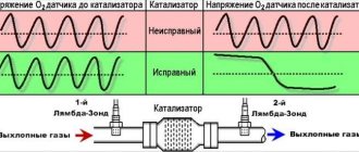
xdcden, Depending on which ECU. But the general test scheme is as follows: Turn off the ignition, disconnect the harness connector from the controller, measure the resistance between the contacts coming from the DCPV with a multimeter (different ECUs have different contact numbers) a) if the resistance is 750 Ohms or more, the connecting wires or sensor are faulty; b) if the resistance is 550 Ohms or less, the wires are shorted to each other or the sensor is faulty; c) if the resistance is within 550-750 Ohms, rotate the crankshaft, using a multimeter to measure the voltage between the contacts of the harness block. If the voltage is below 0.3 V, the connections are faulty or the sensor is faulty. If the voltage is higher than 0.3 V, connect the harness block to the controller, clear errors from the controller’s RAM and try to start the engine. PS The sensor itself generates voltage pulses when the teeth of the crankshaft pulley pass by it
3 Reply from xdcden 2016-03-22 08:13:40
Seryoga Sedovlasy, thanks for the advice. It was decided, it wouldn’t start due to the fact that the wires on the block were mixed up.
Methodology for checking the functionality (diagnostics) of phase sensors (part 21110/21120-3706040) and crankshaft position sensors (part 21120-3847010), used on VAZ cars.
1. Checking the phase sensor 21110-3706040
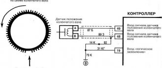
1.1 Set the voltage on the voltmeter V1 on the power supply E to 13.5±0.5V, the voltage at contact “B” of the sensor must be at least 0.9Up. 1.2 Bring a steel plate made of soft magnetic material to the end of the sensor, as shown in the figure. The sensor should operate, which is determined by the change in voltage at contact “B” of the sensor. When the sensor is triggered, the voltage at contact “B” should be no more than 0.4V. 1.3 Remove the steel plate, and the voltage at contact “B” of the sensor should change to a value of at least 0.9 Up.
2. Checking the phase sensor 21120-3706040
2.1 Set the voltage at voltmeter V2 on power supply E to 13.5±0.5V, the voltage at contact “B” should be no more than 0.4V. 2.2 Bring a steel plate made of soft magnetic material with a width of at least 20 mm, a length of at least 80 mm and a thickness of 0.5 mm to the end of the sensor as shown in the figure, placing it in the slot of the housing. The voltage at contact “B” of the sensor must change and be at least 0.9 Up. 2.3 Remove the steel plate, and the voltage at contact “B” of the sensor should change to a value of no more than 0.4V
II. Checking the performance of DPKV (21120-3847010)
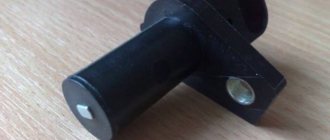
1.1 Remove the sensor. Carry out an external inspection of the sensor for damage to the sensor body, core, contact block and its contacts. Contacts must be clean. If there is contamination on the contacts, remove them with an alcohol-gasoline mixture. If the core is dirty, clean it of metal particles and dirt. 1.2 Check the active resistance of the sensor winding between contacts 1 and 2 of the sensor block using a V7-22A digital voltmeter (or another that provides similar or greater measurement accuracy). The value of active resistance should be in the range of 550-750 Ohms. Checking the active resistance of the sensor should be carried out at a sensor temperature of 22±2°C. When checking active resistance, it is necessary to take into account the error of the measuring device. 1.3 Check the inductance of the sensor winding between contacts 1 and 2 of the block using an R, L, C E7-8 meter at a frequency of 1 kHz. The inductance value should be in the range of 200-420 mH. 1.4 Check the insulation resistance of the sensor between the core and the sensor terminals (contacts 1 and 2 of the block) using a F4108/1 megohmmeter. The insulation resistance must be at least 20 MOhm at a voltage of 500V.
Version 24.10.16 beta
[td] Car reference book
Moving the site to a new domain.
Crankshaft position sensor (CPS)
VAZ ECM sensors. The sensors convert the information into an electrical signal, which is received by the electronic engine control unit. The presence of all sensors is not necessary for the ECM to function. The configurations depend on the injection system and toxicity standards.
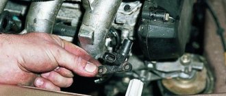
To check the DPKV itself, you need to remove it from the car by unscrewing the mounting bolt and removing the sensor from the hole in the boss on the oil pump housing. By connecting the tester to the sensor terminals, measure the resistance; it should be equal to 550-750 Ohms. Then we switch the tester to the alternating current measurement mode and bring a screwdriver or other metal object to the sensor; the tester should detect voltage surges.
You can check the serviceability of the DPKV sensor using a scanner, which must be connected to the diagnostic connector.
The best and most accurate test for crankshaft position sensor operation. You can do this with a motor tester (oscilloscope).
Technological progress in the automotive industry is displacing outdated carburetor engines, replacing them with injection ones. This leads to the need to know the design and operating principle of modern engines, in terms of the synchronization of spark formation and the supply of gasoline to the cylinders. DPKV is not provided on cars that do not have an on-board computer, and on carburetor engines.
The sensor is available in the design of only injection and diesel internal combustion engines. The stable functioning of a modern car depends on the ECU, which is its “brain”. The unit receives information about the condition of the vehicle from the installed sensors, which is processed, and based on the results obtained, the operation of all systems is adjusted. One of the main sensors responsible for engine operation is the crankshaft position sensor.
Performing a check
You can determine the serviceability of (DPKV) in several ways. Each method requires the use of special devices. Most often, three main methods are used to check the performance of the crankshaft speed controller, let's look at them in order:
- Listening to the advice of professionals, before checking it is always necessary to remove it by unscrewing the fastener of the VAZ 2112 crankshaft sensor, do not forget to fix its initial position on the engine with marks
- Everyone understands that it is necessary to inspect it after removal
- Visual inspection makes it possible to detect external damage on it
- And understand the condition of its contact block and the core of the contacts themselves
- Dirt should be removed from it using alcohol or gasoline.
- The contacts at the crankshaft controller must be clean
- During the removal process, it is necessary to clearly mark the distance from the controller core to the synchronization disk
- Typically it varies from 0.6 millimeters to 1.5 millimeters
- If there are no visible problems, you need to move on to identifying hidden problems in the electrical circuit of this device
Diagnostics using an ohmmeter
To measure the resistance of the crankshaft controller winding, you can use an ohmmeter (multimeter):
- A normally operating controller will show values ranging from 550 Ohms to 750 Ohms
- This test with a multimeter consists of measuring the resistance of the controller inductor
- If the coil is damaged, the sensor characteristics are displayed on the resistance first
- We set the required range and check the resistance with tester probes at the terminals
- This check is the simplest and most basic, so it does not give 100% confidence in the correctness of the diagnosis.
- In order not to doubt the actions being performed, carefully study the instructions included with your car before starting work.
- If the obtained measurement indicators do not fit into the declared interval, then it is necessary to replace the crankshaft speed controller
The second method of checking the performance of the DPKV is more labor-intensive and to implement it, you will need the following devices:
For the reliability of the obtained indicators, the air temperature is important, preferably 20-22 degrees, we do the following:
- We measure the winding resistance with an ohmmeter, as before
- Then we move on to checking the winding inductance using a special meter
- The inductance of a working meter is in the range of 200-400 MegaHertz
- Next, we’ll use a megger and move on to checking the insulation resistance
- At a voltage of 500 Volts, this parameter should not exceed 20 MegaOhm
- If accidental magnetization of the synchronization disk occurs during sensor repair, then you should definitely demagnetize it using a network transformer
- Having analyzed all the data obtained as a result of these measurements, we can draw a conclusion about the performance of the crankshaft controller or the need to replace it
- When installing a new or old device in its place, do not forget to pay very close attention to the marks left during dismantling, remember the need for a distance of 0.5-1.5 millimeters from the controller core to the synchronization disk
- The third method of checking the crankshaft speed controller is the most accurate of all and is used, as a rule, at professional stations
- Since it requires an oscilloscope and a special program
- This method does not require removing the device from the engine.
- Since it allows you to see the signal formation on the screen
- Therefore, the presence of a digital oscilloscope helps specialists to effectively identify various problems that have arisen in the injection system
Why do you need a timing sensor?
DPKV records and transmits the following indicators to the ECU:
- the moment the pistons pass TDC and BDC in the first and last cylinders;
- crankshaft position measurement.
The received data is transmitted to the ECU. As a result of processing information about the position of the crankshaft in relation to the dead points and its rotation frequency, the synchronization sensor corrects the following indicators of the internal combustion engine:
- the volume of gasoline entering the cylinders;
- fuel supply time;
- ignition timing;
- camshaft rotation angle;
- moment and duration of operation of the adsorber valve.
The tasks of the electronic unit may vary depending on the complexity of the internal combustion engine device, but not a single ECU operates without a crankshaft position sensor.
As a result of a malfunction of the DPKV, sparking is either delayed or ahead of the engine's power stroke, which leads to improper operation of the internal combustion engine or to the engine not starting. This contributes to incomplete combustion of the working mixture and, as a result, excessive fuel consumption and a decrease in the dynamic performance of the car.
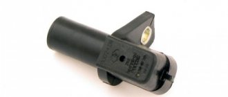
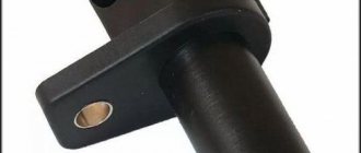
DPKV device
The part is a steel core with a copper wire winding, placed in a plastic case and filled with compound resin.
There are 3 types of synchronization sensors available:
- Induction. The operating principle is based on the use of a magnetized core with copper wire wound on it, at the ends of which the change in voltage is measured. In addition to fixing the position of the crankshaft, it measures its rotation speed, which is also necessary for high-quality operation of the internal combustion engine. Induction sensors are the most common and frequently used in automobile devices.
- Optical. Their design is based on an LED, which emits a luminous flux, and a receiver, which captures the light on the other side. When a light beam hits a control tooth, it is interrupted, the receiver records its absence, and the information is transmitted to the computer.
- Hall Sensor. It works based on the physical effect of the same name. A magnet is placed on the crankshaft; when it passes the sensor, a direct current appears in the latter, fixed by a synchronizing disk.
The versatility of an induction-type device and a Hall sensor make them the most popular in the design of modern motors.
Sensor location
The stable operation of the engine depends on the serviceability of the crankshaft sensor, so automakers place it in an easily accessible place to quickly troubleshoot the problem. Despite the dense arrangement of parts under the hood, it is quite easy to determine where the synchronization sensor is located.
Reference disk. Other names are master or synchronizer.
Most often it is located on a bracket between the generator pulley and the flywheel.
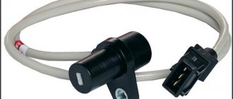
Among other electronic sensors, it stands out because of its wire (70 cm long) with a special connector for connecting to the vehicle’s on-board network.
To replace and install the DPKV, you only need to correctly set the gap between the rod and the synchronizing disk. The gap size varies from 0.5 to 1.5 mm and depends on the make and model of a particular car. The distance is adjusted using special washers located between the device and the installation site.
Something else useful for you:
Video: Crankshaft position sensor DPKV
Examination
Before you can check it, you first need to get to it. And the device is located in a not very convenient place on the engine. So be prepared to spend some time on this.
Now to the question of how to check it. Let's look at the two most common situations, but first, let's remove the element.
- The sensor is removed with a 10 mm wrench;
- Be sure to make special marks on the crankcase and sensor before removing. This will allow you to return it to its original place, or install a new regulator in the correct position;
- If there is no external, visible damage to the crankshaft sensor, then you need to use a multimeter;
- Don't forget to measure the distance between the sensor and the timing disk. In the normal position, the gap ranges from 0.6 to 1.5 millimeters.
First way to check
In this case, you will need an ohmmeter , which you will use to replace the resistance on the winding. According to the manufacturer's standards, the indicator ranges from 550 to 750 Ohms.
It's okay if your numbers are slightly different from the norm. If the deviations are serious, you will definitely have to replace the sensor.
It should be noted in fairness that the crankshaft position sensor on VAZ 2110 models rarely breaks down. Among the main reasons for its failure to function normally is the accumulation of dirt, mechanical damage, as well as banal factory defects.
Second method
Here you will need a voltmeter, a transformer and an inductance meter. It is advisable to measure resistance under compact temperature conditions.
Once the ohmmeter readings are obtained, arm yourself with an inductance measuring device. Normally, the device should show from 200 to 4000 units (millihenry).
Working principle of the synchronization sensor
For stable operation of the engine, the DPKV working process occurs according to the following principle:
- The crankshaft has a special gear (reference disk) with two missing teeth - start and zero.
- When the crankshaft rotates, the teeth, passing through the magnetic field of the DPKV, change it - as a result, pulses are formed in the device, the data of which is transmitted to the control unit;
- When a gear with missing teeth passes past the sensor, the nature of the pulses changes, and the unit determines the initial position of the crankshaft;
- Based on counting the received pulses, the computer determines the position of the crankshaft in a certain period of time:
- After processing the information, the ECU sends signals to the appropriate vehicle systems, and their operation is adjusted.
As a result, stable operation of the car engine is ensured.
Signs of a malfunctioning crankshaft position sensor
The first thing worth noting is that the DPKV does not act up and does not work from time to time; it either functions in a given mode or does not work at all. This is due to the simplicity of the element design. The process of part failure is irreversible. If he has lost his ability to work, he will not work again. This part is non-repairable. If the test confirms its malfunction, it is replaced with a new one.
There are several reasons for its failure. Loads at elevated temperatures, high humidity, sudden changes in temperature and mechanical stress have a negative impact. As a result, the car operates in an unknown mode or does not start.
Signs of a faulty DPKV do not depend on its type. The following symptoms will indicate a breakdown of the crankshaft position sensor:
- a decrease in the vehicle’s traction performance (this sign indicates the need to diagnose the internal combustion engine, but does not always indicate a breakdown of the DPKV);
- instability of engine operation, “swimming” of its speed at idle and when the vehicle is moving;
- engine detonation when the load increases;
- inability to start the engine.
In addition, a broken sensor is indicated by a lack of sparking or a lit "Check Engine" icon on the dashboard.
Before proceeding with the replacement, it is worth understanding that the listed symptoms also appear with other vehicle malfunctions. Therefore, before starting car repairs, a comprehensive diagnosis of the internal combustion engine is carried out to identify the exact cause of the malfunction. This will avoid unnecessary expenses and will contribute to a faster restoration of the vehicle’s performance.
The crankshaft position synchronization sensor is a non-repairable vehicle part and if it malfunctions, it is replaced with a new one.
Causes of failure
There are a small number of reasons why a sensor may fail, but they still exist.
- Mechanical damage;
- Aging;
- Electrical damage;
- Open circuit control;
Let's consider each of the breakdown options in more detail.
Mechanical damage. May be caused by any impact to the sensor. For example, when trying to dismantle the sensor, similar damage may occur.
Aging. Often, on older cars, the sensor may fail due to its aging and demagnetization of the core.
Electrical damage. With such a breakdown, the coil inside the sensor most often breaks, and it stops sending a signal to the ECU.
Open circuit control. A break in the control circuit does not refer to a sensor failure. If there is a break, the wiring that transmits the signal from the sensor to the ECU is damaged.
Methods for diagnosing DPKV
When determining the serviceability of the crankshaft position sensor, we are guided by the principle - from simple to complex. In other words, first an inspection, then checking the characteristics with instruments (ohmmeter, oscilloscope or computer). The absence of moving parts and the simplicity of the design of the element make it a fairly reliable part. Therefore, the crankshaft sensor in rare cases becomes unusable on its own. Most often, it receives mechanical damage during repair work under the hood of a car or as a result of foreign objects getting between the sensor and the gear wheel.
Before you begin diagnosing an electronic component, you need to note its original position on the motor. After dismantling, the device is checked for defects in external surfaces. If the DPKV is dirty or has corrosion on the contact group, then it must be cleaned with alcohol. If the inspection shows no defects, it can be diagnosed using special instruments. It is advisable to carry out the test using a multimeter, which can be switched to different modes.
Ohmmeter test method
This method is simple and accessible, but does not guarantee detection of a breakdown. It is used to measure the resistance of the coil. To do this, it is enough to simultaneously touch the coil terminals with the probes. The polarity of the touch is not important in this case.
The resistance value depends on the characteristics of the coil and is usually in the range of 500-700 Ohms. To determine the resistance value of your sensor model, you need to look in the description of the DPKV or search on the Internet.
The multimeter is used as follows:
- We set the measured parameter (resistance) in a range close to the measured value, but not lower.
- We touch the ends of the sensor with the probes and look at the readings.
If the indicators are close to the standard values, then the coil is working properly. The disadvantage of this method is that it does not always indicate a faulty crankshaft sensor. Therefore, it is advisable to check using other methods.
Checking inductance values
When excited, all coils display an inductance indicator, including the coil located in the crankshaft sensor housing. The diagnostic method boils down to measuring this indicator.
When checking inductance, you must have a megohmmeter, a network transformer, an inductance meter and a voltmeter. To determine the indicator, carry out the following steps:
- Use a multimeter to measure the inductance of the coil (standard values are in the region of 200-400 mH).
- Using a megohmmeter, measure the resistance of the insulating layer between the ends of the DPKV (the data should be above 0.5 MΩ).
- A network transformer is used to demagnetize the sensor coil (deviations indicate the need to replace the part).
Video: Checking DPKV, it couldn’t be simpler. Injector diagnostics.
Diagnostics using an oscilloscope
The most advanced and accurate method of determining the health of a part is checking with an oscilloscope. Diagnostic work is carried out with the power plant running.
You can also use an oscilloscope to check serviceability on a dismantled crankshaft sensor. This requires an electronic oscilloscope and special software. In this case, the check is carried out according to the algorithm:
- Probes must be connected to the terminals of the crankshaft position sensor;
- Launch the software;
- Move any metal object near the part.
If the sensor is working properly, a graph is constructed on the device screen based on the DPKV readings.
If the part reacts to the movement of a metal object, then it is working. But the result of checking it on a running internal combustion engine will be more accurate.
The simplest, most reliable and fastest way to determine the performance of the DPKV is to install a known-good synchronization sensor in place of the one being tested. And if the problems with the car disappear, then the conclusion is clear - the part is faulty and needs to be replaced.
When installing, you should take into account the correct installation: maintaining the required gap between the DPKV and the flywheel. You can find out this indicator from the instructions for the sensor or from the Internet, but on average it is 0.5-1.5 mm.
Today we will talk about the engine crankshaft position sensor, where it is located, signs of its malfunctions, ways to check it on various cars using instruments.
Operating principle and location
It should be noted that malfunctions of the crankshaft sensor (controller here and further in the text) are rare, however, when going on a long trip, it is better to have a spare working sensor, if the DPKV fails, then further driving of the car most often turns out to be impossible. Let's move on to the principle of operation:
- The toothed pulley of the electric generator drive is made in the form of a disk with 58 teeth around its circumference, located every 6 degrees
- In order to generate a speed synchronization pulse for the injector, two teeth are specially missing on the pulley
How it all works
A modern car is equipped with a significant number of various sensors, the main task of which is to monitor the operation of mechanisms or systems.
Data from these sensors is transmitted to an electronic control unit, which, based on the information received, configures the operation of certain systems.
One of the most important of these control elements is the crankshaft position sensor (CPS, TDC sensor).
This sensor monitors the rotation speed of the engine crankshaft.
Based on its readings, the control unit adjusts the operation of the fuel system and ignition system.
To put it simply, based on the DPKV readings, the control unit determines how much fuel to supply to the cylinders and when to do it, as well as at what moment to apply a spark.
Therefore, perhaps, this is the only sensor whose malfunction may prevent the power plant from starting, because a failure in its operation will lead to disruption of the fuel system.
Even if the power plant starts, its operation will be unstable, intermittent, etc. Therefore, this crankshaft sensor is very important and you need to monitor its performance.
Typically this sensor is located near the alternator belt drive pulley. On this pulley there is usually a gear ring made around the circumference, the so-called synchronization disk. It is to the rotation of this disk that the sensor responds.
It is worth noting that in order to accurately obtain data on the rotation of the crankshaft, the DCPV is located at a certain distance from the disk.
For a correctly installed device, the distance between its core and the top of any tooth should be 0.6-1.5 mm.
The location of the DKPV is not the most convenient, but it is quite possible to get to it.
Cars use several different DPKVs in design and operating principles:
- induction (one of the most common);
- sensor using the Hall effect;
- Optic.
We won’t talk about the design and operation features of each of them for now; let’s move straight to the malfunctions.
Video “Replacing DPKV”
https://youtube.com/watch?v=Ghzz6V5Ht3k
In this video, an experienced technician will tell you in detail and show how to replace, in the event of a malfunction, the crankshaft position sensor on VAZ cars.
The crankshaft position sensor for injection engines of VAZ 2108, 2109, 21099 cars is an electromagnet (winding with a steel core inside) that generates an electromagnetic field.
Crankshaft position sensor and its replacement | VAZ repair... https://remont-vaz2109.ru/datchik-polozheniya-kolenvala-i-ego-zamena/The price of a crankshaft sensor on a VAZ 2109 ranges from 300 to 500 rubles, depending on the type, part code and manufacturer. ... Replacing the fuel pump on a carburetor engine.
Replacing the crankshaft position sensor on a VAZ 2108, VAZ... https://Vaz-Russia.ru/remont-vaz-2108/zamena-datchika-polozheniya-kolenvala-na-vaz-2108-vaz-2109-vaz-21099.htmlWhen necessary change the crankshaft position sensor on a VAZ 2108-VAZ 21099? 1) If the engine speed of your car begins to float. ... Replacing the air filter on carburetor VAZ 2108, VAZ 2109, VAZ 21099.
How to change the crankshaft sensor on a VAZ 2109 injector yourself? https://AvtoZam.com/vaz/2109/datchik-polozheniya-kolenvala-neisprav We change the crankshaft position sensor of the VAZ 2109 injector with our own hands. ... In a car with an injector, the crankshaft position sensor performs the same function as the Hall sensor on a car with carburetor injection.
Checking and replacing the crankshaft position sensor... https://autoruk.ru/uaz-patriot/dvigatel-zmz-409/proverka-i-zamena-datchika-polozheniia-kolenchatogo-vala-zmz-409VAZ 2108-2170. UAZ 3151. Avensis Toyota. ... Crankshaft position (synchronization) sensor type (2612.1.113 BOSCH or 406.3847113) inductive type is designed to determine the angular position of the engine crankshaft...
crankshaft position sensor https://myauto.jofo.ru/294516.htmlHow to replace the VAZ 2110 crankshaft position sensor in a VAZ 2110 with your own hands. ... Injection engines replaced carburetor internal combustion engines.
VAZ sensors, principle of operation and diagnostics https://www.drive2.ru/l/1988017/Crankshaft position sensor The crankshaft position sensor (DPKV) is designed to estimate the speed of rotation of the engine crankshaft ... Lada 2109 324 ″ Logbook “VAZ sensors, operating principle and diagnostics.
Signs of a faulty VAZ 2110 crankshaft sensor... https://AutoFlit.ru/1706-priznaki-neispravnosti-datchika-kolenvala-vaz-2110-tochnaya-diagnostika.html It will be useful for many owners to learn about what are the signs of a faulty VAZ 2110 crankshaft sensor. ... When you sharply press the gas pedal, such an unpleasant phenomenon as “failure” appears. In carburetor engines this happens when...
Hall sensor on VAZ 2109: do-it-yourself replacement... | LuxVAZ https://luxvaz.ru/vaz-2109/350-kak-proverit-datchik-holla.html On carburetor VAZ 2109, the Hall sensor (HL) is responsible for opening and closing the contact group. ... On injection VAZ 2109 there is no Hall sensor. Its functions are performed by the crankshaft position sensor.
Important sensors in the VAZ 2109 (carburetor) https://avto-all.com/avtolyubitelyam-na-zametku/vazhnyie-datchiki-v-vaz-2109-karbyurator When troubleshooting, repairing and maintaining, many forget about a number of important sensors that are installed on the car. However, their malfunctions can lead to serious damage to the VAZ 2109 carb.
Sources
- https://vaz-remzona.ru/davlenie-masla-vaz-2101/
- https://avtozam.com/vaz/2112/datchik-polozheniya-kolenvala/
- https://vaz-2101.ru/datchik-kolenvala-na-karbjuratornuju-vaz/
Symptoms of a problem
A malfunction of this device will immediately appear. Symptoms of a faulty DCPV are:
- Inability to start the power plant;
- Decrease in car dynamics while driving;
- Floating speed in different driving modes;
- Interruptions in operation, instability of idle speed;
- Under load, detonation may occur.
It is worth noting that since this sensor is very important for the functioning of the power plant, if it malfunctions, the electronic unit will signal this by lighting up the “Check Engine”.
Of course, the reason for the appearance of this inscription or icon on the dashboard may also be a malfunction in some other system, however, in combination with the indicated symptoms, we can immediately assume that the DCPV is to blame for all the troubles with the car.
Signs of breakdown
Any malfunction of the VAZ 2110 crankshaft sensor will cause the engine to be unable to start after a long period of parking. If the controller starts to malfunction while operating the car, in 90% of cases the engine will stall, since the ECU will not generate a signal to the ignition system, and the internal combustion engine safety function will work. Signs of a sensor malfunction when the unit begins to break down:
- Check Engine is activated on the dashboard;
- engine speed becomes unstable, traction decreases by 50%;
- The VAZ 2110 crankshaft sensor must be urgently changed if the following sign of a malfunction appears: when the speed increases, a hum is felt in the engine area and knocking;
- An injection engine is characterized by the appearance of popping noises in the exhaust tract area.
When the VAZ 2110 dpkv is completely faulty, the engine stalls because the computer does not send signals to form a spark.
These symptoms do not always indicate that a complete replacement of the VAZ 2110 crankshaft sensor is necessary, since all faults of the element are conditionally divided into four groups:
- surface clogging;
- damage to the winding of the device and violation of its integrity;
- manufacturing defects;
- open circuit or short circuit in the circuit.
Checking the sensor begins with cleaning the part. The cleanliness of the contacts, their security, the cleanliness of the connector are checked, and oil stains are eliminated. The design of the sensor is quite simple, but 20 percent of device failures are factory defects. The wiring break is repaired after ringing the circuit. The VAZ 2110 crankshaft sensor is not repaired, since the cost of the consumable does not exceed 100 rubles; the unit is replaced with a similar one after a short diagnosis.
Verification methods
Before going to a car store for a new sensor, it is still recommended to first check the one installed on the car.
This will make it much faster to determine why the car is not working well, because it is possible that the sensor is not to blame for everything, especially since some testing methods are not so complicated.
The most common are:
- checking the resistance of the sensor coil;
- comprehensive check (coil and insulation resistance, winding inductance);
- checking with an oscilloscope.
The first two checks are quite simple; you can perform them yourself if you have the necessary equipment.
The third method is the most accurate, but it can only be checked at specialized stations.
Check for VAZ 2110
To make it more clear, let’s look at each method of checking the crankshaft sensor using the example of several cars.
The first will be the VAZ-2110, which uses an induction type of device.
So, the engine on the “Ten” malfunctioned and there is every assumption that this happened due to the crankshaft sensor. There is a multimeter at hand that can work in ohmmeter mode.
This is quite enough to check the winding resistance.
It is quite possible that there is no gap there due to the fact that dirt has adhered to the sensor or disk, which led to malfunction.
If everything is in order with the gap, we will remove the device from the car.
On the VAZ 2110 it is located on the oil pump cover.
Before doing this, it is better to mark the position of the DPKV.
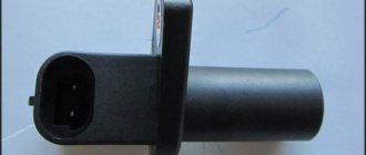
The next stage is assessing the external state. The sensor body must be intact, without signs of damage, the core must be clean, the contact terminals must be free of traces of oxidation, and the wires must not be damaged.
If external contamination is visible on the DPKV, you can wash it before checking (to do this, use only pure gasoline or alcohol), and also clean the contacts with a file.
After cleaning, rinsing and drying, you can start taking measurements. To do this, switch the multimeter to ohmmeter mode and connect the probes to the sensor contacts.
When measuring, a working DPKV should show a resistance in the range of 550-570 Ohms.
For other cars, this indicator may be different, so it is better to inquire about the rated voltage of the sensor in the technical documentation of the car before taking measurements.
If the resistance value is lower or higher than the specified range, the sensor is faulty and must be replaced.
This is the easiest way to check DPKV, but it is also the most inaccurate. It can only give a partial idea of the state of the device, although this is sometimes quite sufficient.
The most accurate method for checking is using an oscilloscope. Therefore, let’s look at how to check the sensor on a VAZ-2110 using this device.
During such a check, there is no need to remove the DCP, and all measurements are taken directly on the car.
Before carrying out the test, you need to correctly connect the oscilloscope to the machine. Typically this device has one clamp and two probes.
The clamp must be connected to the engine ground, that is, to any metal component of the motor.
One probe is installed parallel to the sensor signal output terminal. The second probe is connected to pin 5 on the scanner connector.
After connection, you should switch the device to the “Inductive Crankshaft” mode.
After this, start the engine. If it does not start, then you will need to rotate the crankshaft with the starter so that the oscilloscope takes readings.
After this, the performance of the sensor can be assessed from the resulting oscillogram. Any disturbances in its operation will affect the oscillogram image, and this will be clearly visible.
Description of the crankshaft sensor
So what is this controller and what is its purpose? Where can I find the device in order to replace it? What are the main signs of a device malfunction? We will give answers to these questions below.
Functions and purpose
On an engine with 8 or 16 valves, the DPKV is designed to perform not control options, but to implement phase synchronization for gasoline injection. Also, the crankshaft sensor on the VAZ 2110 transmits an impulse to ignite the air-fuel mixture in the combustion chambers of the power unit. Therefore, if the controller breaks down, this can lead to various vehicle systems not functioning coherently. This means that normal operation of the engine will be impossible.
VAZ 2112 crankshaft sensor
The VAZ 2110 crankshaft sensor itself is an inductive type device; this controller must respond to the passage of teeth on the master disk. This disk is mounted on the generator drive pulley, and the controller itself is installed next to it. There are 58 teeth on the pulley, between which there is a cavity the size of 2 teeth. This cavity allows synchronization with the top dead center of the engine pistons. The moment the depression passes the controller, a corresponding signal is sent to the engine control unit.
There are quite a few designs of devices of this type; the principle of their operation is based on a regulator such as the VAZ 2110 Hall sensor. In the latter case, the regulator also responds to a rotating shaft, but its operation is carried out as a result of the passage of a permanent magnet.
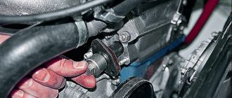
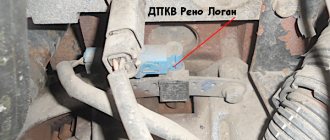
Where is?
If malfunctions are noticed in the operation of the engine, then before you begin to identify the breakdown and signs of malfunction, you need to find out where the regulator is located. Where is the crankshaft position sensor located on an 8- or 16-valve “ten”? If you open the hood, you will notice that the regulator can be found directly on the oil pump cover. As you can see, the location of the regulator is not particularly convenient. VAZ engineers thought through this point, thinking about the convenience of replacing the controller, so they equipped the DPKV with a long 80 cm wire.
Location of the DPKV under the hood of the car
Signs of trouble
If the controller located on the oil pump fails, the driver will not be able to start the engine. In the event of a breakdown, only replacing the regulator will solve the problem of the inability to start the motor. It should be noted that on 8- or 16-valve engines the problem of complete failure of the controller does not often occur; as practice shows, in most cases the problems accumulate.
Comprehensive check for Opel Vectra B
Now let's take another car and use it to consider the last of the verification methods - comprehensive.
This test is much better than with a conventional multimeter, but in terms of accuracy it is not as accurate as an oscilloscope.
The problem car will now be the Opel Vectra B. We leave the symptoms the same.
The initial work is also no different from the VAZ-2110: the sensor is removed, inspected, thoroughly washed, and only after that you can start checking the condition.
But for a comprehensive check you will need more equipment:
- Multimeter;
- Megaohmmeter;
- Device for measuring inductance.
It is better to take all measurements in a heated room so that the readings are correct.
First, the coil resistance is measured, as described above. Resistance readings must be within the range specified in the technical documentation.
The next check is to measure the winding inductance, for which a device is used to measure it. A working DPKV inductance should be in the range of 200-400 mH.
The devices are pictured below.
The insulation resistance is also checked with a megohmmeter. When a voltage of 500 V is applied, the resistance value of the sensor should be no more than 20 MΩ.
Based on these measurements, it is determined whether the DPKV is working or requires replacement.
Photos of the devices are below.
Sensor check
The check must be carried out in two stages: a visual check and a check with a multimeter. These two methods will help you accurately determine whether the sensor is working or not.
Visual inspection
It is necessary to look at the sensor and assess its condition; there should be no debris or various shavings on the metal part of the sensor.
Remove the connector from the sensor and assess the condition of the contacts. The connector should be free of moisture and rust.
Checking with a multimeter
To check with a multimeter, you need to set the device to resistance measurement mode.
Connect the probes to the sensor terminals and measure the resistance should be from 500 to 800 Ohms. If the multimeter shows infinity, then the winding is broken.
If after checking it turns out that the sensor is working, you need to check the drive pulley.
Most often, the pulley is made on a damper, which over time can lead to detachment of the rubber from the metal and the pulley turning.
Damper burst