Lada Priora cars are equipped with two oxygen concentration sensors (hereinafter referred to as OCC). The top one is diagnostic, the bottom one is control.
The controllers are designed to determine the quantitative composition of oxygen in the exhaust gases for the purpose of subsequent adjustment of the ignition angle.
An excess amount of air in the fuel mixture, as well as an insufficient amount, negatively affects the functionality of the technical device. Most often, fuel consumption increases, passive acceleration dynamics, and unstable idling.
During systematic operation of the machine, refueling with low-quality fuel, the controllers fail. The process of self-replacement is not complicated, but requires attentiveness on the part of the master. Violation of the regulations is not acceptable.
Types of sensors and operating principle
The lambda probe is installed in the exhaust system.
Sensors are divided into two types: two-point and broadband. The two-point sensor consists of ceramics, the elements of which are coated with zirconium dioxide on both sides. Installed in front of or behind the catalytic converter.
The principle of operation is to measure the level of oxygen concentration in the environment and exhaust gases. If the level changes and becomes different, a voltage is created at the ends of the sensor elements, from low to high. Low voltage is created if there is excess oxygen in the system.
Otherwise, if the system does not have the required level of oxygen, high voltage will be created. These signals are sent to the engine control unit, which distinguishes them by current strength.
The wideband sensor is a more modern design. It also has two ceramic elements. One of them can be called “pumping”. It is responsible for activating the process of pumping or removing air from the system.
The second element can be conventionally called “two-point”. The principle of operation is based on the fact that as long as there is the required amount of oxygen in the mixture, the current strength on the “pumping” element does not change and is transferred to the “two-point” element.
It, in turn, receiving a constant current from the “pumping” element, maintains a constant voltage between its elements and is inactive.
As soon as the oxygen level changes, the "pumping" element supplies the changed voltage to the "two-point". This, in turn, ensures either pumping air into the system or pumping it back.
Device diagram
Let's look at the probe diagram to give an idea of the node placement. Knowledge of the design allows you to understand the position of parts susceptible to failure.
Probe design example
- 1 - metal fitting, designed for installing a probe, there are turnkey edges on the outer surface, the thread is located at the bottom;
- 2 - ceramic insulator;
- 3 - sealing element for entering electrical wiring;
- 4 - signal cables;
- 5 - metal protective cap with ventilation ducts, designed to protect the measuring element from damage;
- 6 — spring contact part;
- 7 — ceramic sensitive element;
- 8 - heating rod;
- 9 - ventilation duct;
- 10 - outer metal casing.
Lambda probe on VAZ cars
Lada Priora Sedan Logbook Preparing for winter.
Starter VAZs use several types of sensors:
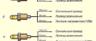
1. Bosch No. 0 258 005 133, Euro standard – 2. Installed on outdated models with an engine capacity of 1.5 liters. On later models with Euro 3 standard, this sensor was used as the first one, and was installed before the catalyst.
The second sensor was installed, which has a “return connector”. But you can find two identical sensors installed
2. Bosch No. 0 258 006537 was installed on cars manufactured since October 2004. They have a heating element in their structure.
Lambda probes produced are interchangeable with zirconium sensors of similar structure
Please note that a non-heated sensor can be replaced with a heated sensor. Not the other way around
Replacement
Connection wire
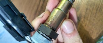
Replacing the lambda probe is not at all difficult. The main thing here is to find a device identical to the old one. For this purpose, the sensors have corresponding markings, by which you can easily find an analogue.
- Wait until the engine cools down completely. Make sure the ignition is turned off;
- The old sensor is dismantled with a regular wrench. Just before this, be sure to disconnect the wires going to the lambda probe;
- Next, a new device is installed;
- The new sensor should be screwed in carefully, since excessive force on the wrench may cause the thread to break;
- Reconnect the wires and check the new probe in operation.
As you can see, checking and replacing the oxygen sensor on the VAZ 2110 is quite simple. You don't have to be a professional. Follow the instructions and only use a similar probe, as a device with a different marking simply will not function.
Oxygen sensor malfunctions and error codes
Lada Priora Sedan constructor, assemble it yourself Logbook Mileage and clutch replacement
Among the possible breakdowns of the lambda probe, the following can be distinguished: loss of sensitivity, non-working heating. As a rule, the on-board computer will not show you a breakdown if the problem is loss of sensitivity. It’s another matter if the heating circuit breaks, then the malfunction will be recorded.
- Error P1115 - a breakdown has occurred in the heating circuit
- Error P1102 - low resistance on the oxygen heater
- Error P0141 - the heater has broken down on the second sensor
- Error P0140 – sensor number two has broken
- Error P0138 - the second sensor indicates an excessive signal level
- Error P0137 - the second sensor indicates a reduced signal level
- Error P0136 – there is a short circuit to ground of the second sensor
- Error P0135 - the heater on the first sensor has failed
- Error P0134 – the first sensor has no signal
- Error P0133 - the first sensor responds slowly to the request
- Error P0132 – there is little oxygen in the system, the signal is high at the first sensor
- Error P0131 – there is a lot of oxygen in the system, the signal is low at the first sensor
- Error P0130 - the first sensor sends incorrect signals
Visual inspection
The check should always begin with a visual examination of the condition of the oxygen sensor.
- Inspect the wires. They must be intact, without traces of damage or defects. Check all connectors for tight connections.
- Soot on the lambda probe indicates a malfunction of the device heater. Also, such deposits are caused by an excessively rich air-fuel mixture.
- If you notice shiny deposits on the surface of the element, this indicates an excess of lead in the fuel you are filling the tank with. This situation requires mandatory replacement of the oxygen sensor, since lead could damage the internal device.
- Gray or white deposits are the result of various types of fuel additives affecting the sensor. They often cause the probe to break and have to be replaced.
How to replace an oxygen sensor on a VAZ 2170-VAZ 2172
Lada Priora Sedan Logbook Replacing valve seals
When you come to a car shop or market, there will be a small but not small selection of oxygen sensors (If the store is specialized), some will come with a heating element, and some will not, Lada Priora cars are equipped with sensors with a heating element from the factory, therefore, when choosing, you will need to take exactly this one, it will be more expensive, but the whole point is as follows, the oxygen sensors begin to work normally only when they heat up to 300 ° C, at first, by the way, the car (Until it is warmed up) works at all according to other sensors, the oxygen sensor only comes into operation when it is warmed up and so that it does not warm up for a long time, this heating element is built into it, so don’t make a mistake when purchasing!
1) Both sensors, diagnostic and regulating, are removed in exactly the same way, so we will show an example of replacement at the top one. At the beginning, if the car is warm, let it cool completely, because at engine operating temperature, the temperature of the exhaust manifold reaches about 300- 500 °C, and maybe more if the car sneaks into traffic jams in warm weather and thereby warms up, after the engine has cooled down, remove the wire that is attached to it from the negative terminal of the battery (If you do not know how to do this, then study the article under title: “Replacing the battery”, everything is described there in point 1) and then press the lock, which is indicated by an arrow in the photo below, and disconnect the wire block and the connector that comes from the oxygen sensor.
2) Remove the following wire from the oxygen sensor from the heat-insulating shield, it is attached to it by a latch, to remove it, you just need to squeeze the latch (Latch) with your hands and remove it from the hole in the shield as shown in the first picture in the photo below and finally using a wrench or a special socket that can be found in a car store (a high socket with a split sector, it’s called, a very convenient thing, if you work with cars in the future, then purchase it, but if you are replacing it only for yourself then you don’t need it, because you can do it with a wrench) unscrew the oxygen sensor itself as shown in the second picture, in the photo below:
The new sensor is installed in its place in the reverse order of removal; by the way, we recommend lubricating the threads of the sensor with good graphite grease before installation.
Checking the oxygen sensor:
1. Any sensor, any part needs to be checked before running to the store and buying a new one. To check the oxygen sensor, you will need to stock up on a voltmeter and a paper clip, or a laptop and a diagnostic cable. Let’s first start by describing the first option, it is as follows: find the signal wire coming from the oxygen sensor on the connector, it can be of any color, but as a rule it goes black, so if you have a black wire, you can try to start with it, namely, to it you will need to connect the positive wire coming from the voltmeter (Through you need to connect a paperclip), and throw the negative wire to ground (the car engine can be the ground) and after starting the car, you will need to look at the readings that the voltmeter will give, they should not go beyond 1 and should not stand at 0, that is, in In the area of 0.01-0.99, the readings should fluctuate, if this is the case, then the sensor is working, but if the readings with the engine running freeze at any mark (For example, 0.32), then the sensor is faulty and needs to be replaced.
This method of verification, which is indicated in paragraph 1, by the way, is also shown in the video, which is posted below:
2. Now the second method, which is done using a laptop, and it consists of the following, connect the laptop to the brains of the car via a diagnostic connector and wire, then start it up and set all the data on the oxygen sensors on the laptop through the appropriate program and make sure that they fluctuate and do not stand in one place, you can see in more detail how to carry out this procedure using the example of a Lada Kalina car, as shown in the video clip below.
You can clearly see the process of removing this sensor from the exhaust manifold of a car in the video clip located just below:
Is it true that if you turn off the oxygen sensor and reflash the car, it will drive significantly better?
It won’t go much faster, but it will also depend on who stitched the car, in addition, emissions into the atmosphere from the exhaust pipe will worsen, that is, they will be dirtier and thus the environment will suffer from this!
Assignment of contacts of Bosch ME17.9.7 ECU
The table shows the assignment of contacts for controllers 21126 – 1411020-40, 11194 – 1411020-20. The difference in connection for controllers 21214 – 1411010-50 is highlighted in blue.
| № | Output purpose | № | Output purpose |
| Section X2 | Section X1 | ||
| 1 | Entrance. Crankshaft Position Sensor B | 1 | not connected |
| 2 | Entrance. Oxygen sensor 2 | 2 | not connected |
| 3 | Entrance. Other damper position sensor 1 | 3 | Weight of analog sensors |
| 4 | Weight of DC 1 | 4 | Weight of analog sensors |
| 5 | Weight of DTOZH | 5 | Accelerator pedal sensor 1 ground |
| 6 | Weight of DK 2 | 6 | Accelerator pedal sensor 2 ground |
| 7 | Weight of other damper position sensors | 7 | Refrigerant pressure sensor input (level 2) (not used) |
| 8 | Air flow sensor weight and temp. air | 8 | not connected |
| 9 | not connected | 9 | not connected |
| 10 | not connected | 10 | not connected |
| 11 | not connected | 11 | Accelerator pedal sensor 2 |
| 12 | not connected | 12 | not connected |
| 13 | Entrance. Crankshaft position sensor A | 13 | not connected |
| 14 | not connected | 14 | not connected |
| 15 | Entrance. DTOZH | 15 | Exit. Main relay |
| 16 | not connected | 16 | Entrance. Ignition switch terminal 15 |
| 17 | not connected | 17 | not connected |
| 18 | not connected | 18 | not connected |
| 19 | not connected | 19 | Entrance. Refrigerant pressure sensor (1 and 3) level (not used) |
| 20 | Entrance. Other damper position sensor 2 | 20 | not connected |
| 21 | not connected | 21 | Entrance. Accelerator pedal sensor 1 |
| 22 | not connected | 22 | Entrance. Fan diagnostics (not used) |
| 23 | Power supply (3.3V) for other damper position sensors | 23 | not connected |
| 24 | not connected | 24 | not connected |
| 25 | not connected | 25 | not connected |
| 26 | not connected | 26 | Power (3.3V) accelerator pedal sensor 2 |
| 27 | Entrance. Intake air temperature sensor | 27 | K‑Line |
| 28 | not connected | 28 | Exit. Tachometer |
| 29 | not connected | 29 | Exit. Fuel consumption signal |
| 30 | Entrance. Oxygen sensor 1 | 30 | not connected |
| 31 | Entrance. Camshaft position sensor | 31 | Exit. A/C relay (not used) |
| 32 | Entrance. Vehicle speed sensor | 32 | CAN‑H |
| 33 | Entrance. Mass Air Flow Sensor Input. Air flow sensor (frequency) | 33 | not connected |
| 34 | not connected | 34 | Entrance. Request to turn on the air conditioner (not used) |
| 35 | Exit. Canister purge valve | 35 | Entrance. Brake pedal switch 1 |
| 36 | not connected | 36 | Entrance. Clutch pedal switch |
| 37 | Entrance. Knock sensor – terminal 1 “+” | 37 | Power supply (5V) air flow sensor |
| 38 | Entrance. Knock sensor – terminal 2 “-” | 38 | Power supply (3.3V) accelerator pedal position sensor 1 |
| 39 | Exit. Heater DK 2 | 39 | not connected |
| 40 | not connected | 40 | Exit. MIL warning lamp |
| 41 | not connected | 41 | Exit. Fan relay 1 |
| 42 | Exit. Injector 2 cylinders | 42 | Exit. Fuel pump relay |
| 43 | Exit. Injector 3 cylinders | 43 | not connected |
| 44 | Exit. Injector 1 cylinder | 44 | CAN‑L |
| 45 | Exit. Injector 4 cylinders | 45 | not connected |
| 46 | Exit. Heater DC 1 | 46 | not connected |
| 47 | Weight of sensors Weight of electronics | 47 | Brake pedal switch 2 |
| 48 | not connected | 48 | not connected |
| 49 | not connected | 49 | not connected |
| 50 | Weight of output stages | 50 | not connected |
| 51 | Exit. Throttle valve drive 1 “+” | 51 | Exit. Starter relay |
| 52 | Exit. Throttle valve drive 2 "-" | 52 | Exit. Fan relay 2 |
| 53 | Ignition coil 2 cylinders (not used) | 53 | Weight of output stages |
| 54 | Ignition coil 3 cylinders Ignition coil 2.3 cylinders | 54 | Weight of output stages |
| 55 | Ignition coil 4 cylinders (not used) | 55 | Output +AB after the Main Relay |
| 56 | Ignition coil 1 cylinder Ignition coil 1.4 cylinders | 56 | Output +AB after the Main Relay |
The principle of operation of an oxygen sensor on a car
This sensor also has another name. Lambda probe, what kind of design is it and where did the name come from? The sensor is based on a ceramic solid electrolyte made of zirconium dioxide, which is in turn coated with yttrium oxide. In total, conductive, porous platinum electrodes are sprayed on top of the ceramic element.
The principle of operation is similar to that of a galvanic cell. After installation in the exhaust manifold, it heats up in the exhaust gas flow to 400 - 300 degrees. It is in the heated state that the zirconium electrolyte acquires conductivity and ensures its normal functioning. The lambda probe is installed in such a way that one of the electrodes breathes external air - a mixture of exhaust gases. When the amount of oxygen changes on one of the electrodes, a potential difference occurs, which is transmitted in the form of a signal to the engine control system, which regulates the fuel supply in a scientific manner.
In injection about the ratios of elements in nature, stoichiometry, means lambda is the ratio of the actual amount of air to Because.
necessary, the oxygen sensor is included in the heating operation after the working element up to 350 degrees; their first samples tried to be placed as close as possible to the exhaust manifold. Over time, the sensor was built in and a heating element was upgraded into it, which brought it into working condition much faster, and now the question of where the lambda probe is located in the exhaust system is not so important. Structurally, a modern oxygen sensor consists of the following elements.
- Ceramic protective shields with tips and openings for sampling, on one side of the exhaust gases, on the other - atmospheric prisoners, air in the middle part in a ceramic insulator. They are the main working element of all This. The devices just have electrodes from which the potential difference is removed.
- A conductive heating element is located inside these tips.
- In the middle there is a part of the electrical signal current collector.
- All except for the elements of the sensitive parts of the ceramic tips, a metal housing with a thread is enclosed, which is designed to fix the sensor in the receiving pipe housing.
- Currently, modern sensors are equipped with a set of fixed wires and a sealing collar. Such four-wire sensors are called lambda probe. Two white wires are the heating system contact wires, one signal wire is black and black (or white) with a stripe - “more”. On early samples that are still used today, the potential difference was determined between the wire that went from the sensor to the ECU and the ground on the sensor housing. To do this, before screwing it into the mounting location, the sensor was coated with a specific conductive substance. lubricant caused sensitivity and burnout of the sensor due to exposure to high temperatures. This flaw has now been eliminated.
A set of oxygen sensor wires with its other end, through a plug box, is connected to the electronic on-board device, which requests data from the lambda probe about the state of the mixture with a frequency of 2 times per second at idle and more often when increasing speed. Analyzing the received data on the presence of oxygen in the exhaust gas mixture, the ECU adjusts the amount of fuel injected into the engine, making the mixture richer or leaner, depending on the oxygen signals received by the sensor. He strives for the optimal value of 14.7:1, which is included in his program.
The performance of the sensor is checked by testing with a measuring device. The lower level of the signal should be 0.1 - 0.2 V, the upper level should be within 0.8 - 0.9 V. The guaranteed performance of these sensors is very high. Signs of a lambda malfunction of a probe manufactured in accordance with GOST begin to appear no earlier than after a run of 80 thousand kilometers, and on average they can withstand a load of 160 thousand kilometers. However, according to VAZ service book 2114, replacing the oxygen sensor after a mileage of 80 thousand km is recommended. The fact is that although it continues to maintain its performance, its sensitivity is still significantly reduced, which means fuel consumption indicators, for example, are deteriorating.
LADA PRIORA 21723
Assignment of contacts of the instrument cluster block
1 To the electric power steering 2 To the hazard warning lamp 3 To the emergency oil pressure sensor 4 To the parking brake switch 5 To the immobilizer control unit 6 To the airbag control unit 7 To the exterior lighting switch 8 To the turn signal switch (starboard side) 9 To the indicator switch turn (left side) 10 To the fuel injection system control unit 11 To the front passenger airbag deactivation sensor 12 To the seat belt sensor not fastened 13 To the control unit of the electronic brake force distributor 14 To the “RESET” button on the steering column switch (-) 15 To the level sensor brake fluid 16 To the control sensor of the anti-lock braking system 17 To the high beam switch 18 To the instrument cluster lighting switch 19 Housing 20 To terminal “30” of the battery 21 To terminal “15” of the ignition switch 22 To the fuel consumption sensor 23 To the function switching mode key trip computer in a ring forward and changing the minutes (-) 24 To the mode key for switching the functions of the trip computer in a ring back and setting the clock (-) 25 To the outside temperature sensor (-) 26 To the outside temperature sensor (+) 27 To the fuel level sensor 28 To the speed sensor 29 To the coolant temperature sensor 30 Low-voltage tachometer input 31 Diagnostics during production of the instrument cluster 32 To the “L” terminal of the generator relay regulator
List of elements of the electrical connection diagram of the rear wiring harness of LADA PRIORA
1 – rear wiring harness block to the instrument panel wiring harness block; 2 – rear wiring harness block to additional wiring harness block 2 (left rear door); 3 – rear wiring harness block to side door wiring harness block (right front door); 4 – left side direction indicator; 5 – electrical package controller; 6 – right side direction indicator; 7 – interior lighting unit; 8 – handbrake warning lamp switch; 9 – left lamp; 10 – right lamp; 11 – interior air temperature sensor; 12 – interior lamp switch in the driver’s door pillar; 13 – switch for the interior lighting in the pillar of the right front door; 14 – switch for the interior lighting in the pillar of the right rear door; 15 – interior light switch in the left rear door pillar; 16 – block of the rear wiring harness to the block of the wiring harness of the side doors 2 (left front door); 17 – block of the rear wiring harness to the block of the additional wiring harness (right rear door); 18 – blocks of the rear wiring harness to the rear right loudspeaker; 19 – blocks of the rear wiring harness to the rear left loudspeaker; 20 – cigarette lighter; 21 – electric fuel pump module; 22, 23 – rear wiring harness blocks to instrument panel wiring harness blocks 2,3; 24 – trunk lighting; 25 – additional brake signal; 26 – trunk lock drive switch; 27 – interior lamp; 28 – rear wiring harness block to the front wiring harness block; 29 – left rear speed sensor; 30 – right rear speed sensor; 31 – sensor for automatic glass cleaning system (rain sensor); 32 – rain sensor sensitivity regulator; 33 – rear wiring harness block to instrument panel wiring harness block 4; 34 – block of the rear wiring harness to the block of the wiring harness of the parking system sensors; 35 – alarm unit for safe parking system; 36 – driver’s seat belt pretensioner; 37 – passenger seat belt pretensioner; 38 – rear wiring harness block to side door wiring harness block 3 (right front door); 39 – airbag control unit; 40 – parking system control unit; 41 – block of the rear wiring harness to the block of the rear additional wiring harness (tailgate); 42 – rear wiring harness block to rear additional wiring harness block 2 (tailgate); 43 – left seat heater; 44 – switch for electric seat heaters; 45 – right seat heater. 46 – rear wiring harness block to the parking system switch.
VAZ 2114 signs of lambda probe malfunction
AutoFlit.ru
Lambda probe restoration
xn--2111-43da1a8c.xn--p1ai
Signs of a malfunction of the VAZ 2114 knock sensor. List and comments from the service station
- The engine begins to throttle. This is to say that the DD does not send signals to the control system, and it does not adjust the ignition timing;
- The dynamics noticeably deteriorate, the car begins to stall when accelerating;
- Acceleration becomes slow, the engine roars, and the car picks up speed slowly;
- The "Check Engine" comes on when you take off, when you roll downhill, and when you accelerate. Moreover, if the “Check” lights up only when the ignition is turned on, and goes out after 6 seconds, this is normal: the “brains” test all the components of the car.
- Code 0325 indicates that there is a break in the power wire. The most common version of what happened is oxidation of the contacts; the wiring itself breaks extremely rarely. Cleaning the terminals will eliminate the problem in most cases. However, if after processing the error does not disappear, you need to check the timing belt: it means it has jumped several teeth. After marking it, the problem disappears;
- 0328 in most cases signals a malfunction of high-voltage wires, but in some cases it can again indicate a belt jump;
- 0326 and 0327 indicate a low signal coming from the knock sensor. There are 2 options here: either the DD tightening has become loose, or the contacts have again oxidized.
- Turn off the ignition and climb under the hood;
- If there is a 2-pin knock sensor, the nut is twisted with a 13 wrench; if it is a 1-pin, use a 22 wrench;
- The multimeter (or voltmeter) is set to operate with a maximum of 200 MV;
- The electrodes of the device are connected to the DD terminals. It is officially believed that the voltmeter reading (they say there is voltage) is sufficient. However, experienced drivers do not think so: the sensor must respond to shocks caused by detonation. Therefore, additional research is carried out: the sensor is lightly tapped with the handle of a screwdriver; During impacts, the meter readings should change. If they remain constant, the DD requires replacement.
AutoFlit.ru
AutoFlit.ru
How does a lambda probe affect engine operation, its signs of malfunction
The lambda oxygen sensor has a direct impact on the stable operation of the engine by maintaining the desired mixture composition for engine operation:
- the engine is stable, without hesitation, idling at running speed;
- when you sharply press the gas pedal, a timely adjustment occurs in the engine mixture supply corresponding to the changing speed, so there are no jerks or tripping;
- The best-burnt exhaust gases are released into the atmosphere due to the efficient operation of the catalyst, which burns harmful exhaust gases in the pipe.
To ensure normal operating conditions for the sensor and extend its life, it is necessary to comply with a number of conditions:
- Use only the gasoline that is recommended for the 2114 VAZ.
- When working with additives, check their approval and quality for use.
- Under no circumstances should you use sealants, especially silicone, for mounting the sensor.
- Do not allow multiple startup attempts within a short period of time and disable it.
- Do not timing the spark plug when checking cylinder operation.
- Do not allow the exhaust system to overheat due to burnt or accumulated fuel in it; the sensor can only withstand temperatures up to 950 degrees.
- Do not wash any tips made from chemically active liquids.
- Ensure tightness at the junction of the sensor and the pipe.
which, based on the signs, can be determined that the VAZ 2114 oxygen sensor needs to be replaced can be small:
- While on gas, the engine runs unstably, the speed fluctuates or the engine stalls;
- there is an increased steady fuel consumption under standard conditions;
- the dynamic characteristics of the car have deteriorated;
- characteristic cracking of the catalyst after turning off the engine, and also a specific smell of rotten eggs due to the catalyst getting into contact with a large amount of unburned gasoline;
- on-board signal to the computer about errors associated with failures in the lambda probe.
Most often, with a faulty oxygen sensor, all of the listed symptoms should appear and when a situation arises with its replacement, the question will arise which oxygen sensor is on the 2114 VAZ. Depending on the year of manufacture of the car, the exhaust system can contain both single-wire sensors the size of the sensors from the body, and four-wire ones. The price of a VAZ 2114 lambda probe in this case can range from 1,200 to 3,000 thousand rubles.
If, after removal, a strong deposit is detected on the sensor and it shows that the potential difference is not very different from the permissible ones, then this deposit can be removed. To do this, heat the sensor very strongly, and then sharply carbonate it. Cool it should crack and fall off, cover it with a soft bone.
https://youtube.com/watch?v=ns_4VPtpVH8
Some motorists are interested in how car mechanics can disable the VAZ Sama lambda probe. 2114 the procedure is not complicated, but its necessity is highly doubtful. In this case, the ECU begins to supply gasoline for injection at average values, and this will immediately affect stable engine operation, increased fuel consumption and deterioration of exhaust characteristics. Not to mention the fact that the on-board computer will need to be re-flashed, since it will constantly produce an error associated with the absence of the Source sensor.
Is it worth installing a decoy instead of a lambda on a Priora: we reveal all the secrets of using decoys
It’s worth noting right away that the lambda probe decoy is a special insert into which the sensor is screwed. It is needed so that in the event of a malfunction of the catalyst (or its absence), the diagnostic oxygen sensor transmits the necessary readings to the ECU. It is not recommended to install a fake instead of a lambda control, because in this case the engine will not work correctly. A spacer is installed only and exclusively in order to deceive the ECU about the real state of affairs in the exhaust system.
It is not recommended to operate a car with a faulty catalyst, as this will lead to other problems. That is why decoys are usually installed on the second DC to show the ECU that the catalyst is theoretically working properly (in fact, it may be faulty or missing). In this case, you will not need to change the firmware to Euro-2. It is also important to understand that the firmware does not solve the problem if the oxygen sensor is faulty. This device must function properly, and only in this case the motor will work correctly.
The snag costs much less than a new catalyst or ECU firmware. The installation process takes no more than 15 minutes.
In conclusion, we should summarize and note the fact that many car owners consider the lambda sensor to be an unimportant element on the car, and often they are simply removed along with the catalysts, installing 4-2-1 “spiders” and other types of devices. However, this approach is fundamentally wrong. After this, complaints arise about high consumption, low dynamics and unstable operation of the internal combustion engine. It's all because of this minor (at first glance, to a person who doesn't understand) alteration. It is important to take a responsible approach to repairing your car, because any alterations contribute not only to the deterioration of its functionality, but also to a reduction in its service life.
Causes of malfunction and obvious signs
As a rule, the following reasons lead to malfunction of the sensor:
- Some aggressive liquid, such as antifreeze or brake fluid, gets on the sensor.
- Problems may begin if the owner used chemically active agents when cleaning the regulator body.
- If the car fuel contains a large amount of lead compounds.
- In case of significant overheating of the regulator, which occurs either due to the use of low quality fuel or due to a clogged filter.
Regulator malfunctions can be judged by obvious external signs. It's easy to notice
It is enough to pay attention to the following points:
- Fuel consumption has increased sharply.
- The car jerks jerkily, even when the engine is warm.
- The color and smell of the exhaust gases have changed.
- The operation of the catalyst is disrupted.
steps
In turn, experts see two main stages in the deterioration of the sensor.
At the first stage of sensor malfunction, there is an increase in the engine response time to pressing the gas pedal. The power unit reacts sluggishly, when you press the accelerator the “check” starts blinking, the pedal is lowered and the blinking stops. At this stage of the malfunction, the driver notices a deterioration in traction, acceleration dynamics and an increase in fuel consumption (not yet significant). As a rule, this stage of regulator malfunction can last about a year.
The second stage is much sadder. Most car owners at this stage think about why this oxygen sensor is actually needed. Normal acceleration disappears completely, the car “stumbles” even on a completely flat road. Another distinctive feature of the second stage is a decrease in the speed of the power unit, even when the accelerator is pressed to the floor. In this case, popping noises may be heard in the intake manifold.
To be completely sure, it is recommended to start the car “cold”. If the oxygen sensor is faulty on the second severity scale, the car will only run perfectly for the first few minutes. When the device starts functioning, sending signals to the ECU, problems will immediately arise.
Operating principle of the oxygen sensor
The principle of the oxygen sensor on the Priora is as follows: for the parameters for correcting the travel time of the electronic injection signals of the system, data on the composition of oxygen (exhaust) in oxygen gases is taken into account. It is this data and the sensor that represents the oxygen concentration of the Priora, which chemically reacts with the exhaust gases during transport.
In order for this electrochemical reaction to occur, a potential difference is created at the output terminals of the device. voltage drops Changes in voltage determine the oxygen content and air-fuel mixture quality. Changes occur in parameters ranging from 0.1 V, indicating a high oxygen content and a lean mixture, to 0.9 V, indicating a low oxygen content and an enriched consistency.
For optimal operation of the vehicle, the temperature value of the oxygen sensor, the price of which is affordable for most Russian motorists, should not be less than 300°C. Taking this into account, to heat the dynamic device after starting the power sensor, a heating type component is integrated into the oxygen installations on the Priora.
By fixing the voltage at the output of the device, the controller selects a command signal to correct the air-fuel mixture to the fuel atomization components. system for lean mixture readings, i.e. the potential difference is at a minimum value, the controller commands the incoming consistency to be enriched, and with the parameters enriched at, i.e. mixture of maximum potential difference values, the command is sent to deplete it.
In short, a standard lambda sensor (oxygen probe) makes it possible to estimate the unspent oxygen concentration in the exhaust mixture, and based on these studies, the on-board computer changes the consistency of the air-fuel mixture. Occurring malfunctions of the oxygen sensor result in incorrect operation of the vehicle's power plant. Often on car enthusiast forums one comes across the question: Is the oxygen sensor installed on the Priora? car For Lada Priora, only the BOSCH LS6537 sensor is acceptable for installation.
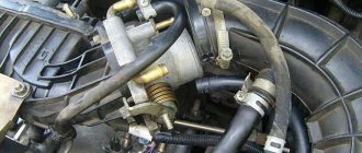
Where is
Priora oxygen sensors are located on the exhaust manifold before and after the catalyst. The exhaust manifold has two threaded holes into which the DC valves are screwed.
The first sensor is regulating, that is, this sensor measures exhaust gases and transmits readings to the ECU, which processes them and adjusts the fuel mixture for cleaner exhaust gases. All this is necessary for Euro standards.
The second sensor is diagnostic; it checks the condition of the catalyst. If the catalyst is in poor condition, the sensor sends a signal to the ECU and the “CheckEngine” lamp lights up.
Operating principle of the oxygen sensor
The principle of operation of the oxygen sensor on the Priora is as follows: to correct the parameters of the transmission time of electronic signals of the injection system, data on the composition of oxygen (oxygen) in the exhaust gases is taken into account. It is this data that is represented by the Priora oxygen concentration sensor, which enters into a chemical reaction with the exhaust gases of the vehicle.
During the course of this electrochemical reaction, a potential difference is created at the output contacts of the device. Changes in voltage drop determine the oxygen content and the quality of the air-fuel mixture. Changes occur in parameters from 0.1 V, indicating increased oxygen content and a lean mixture, to 0.9 V, indicating low oxygen content and a rich mixture.
For optimal operation of the vehicle, the temperature value of the oxygen sensor, the price of which is affordable for most Russian motorists, must be at least 300C. Taking this into account, for dynamic heating of the device after starting the power plant, a heating-type component is integrated into the oxygen sensor on the Priora.
By fixing the voltage at the output of the device, the controller selects a command signal to correct the fuel-air mixture to the atomization components of the fuel system. When the lean mixture reading is indicated, i.e. the potential difference is at a minimum value, the controller commands to enrich the incoming mixture, and with the parameters of the enriched mixture, i.e. at maximum values of the potential difference, a command is received to deplete it.
How to check
oxygen sensor (
lambda probe
) Several methods.
https://youtube.com/watch?v=hXI5whguE1c
In short, a standard oxygen sensor (lambda probe) makes it possible to estimate the concentration of unspent oxygen in the exhaust mixture, and based on these studies, the on-board computer changes the consistency of the fuel-air mixture. Malfunctions of the oxygen sensor result in incorrect operation of the vehicle's power plant. The question often comes up on car enthusiast forums, which oxygen sensor is installed on the Priora? For the Lada Priora car, only the BOSCH LS6537 sensor is acceptable for installation.
How to check the oxygen concentration sensor
You can check the oxygen sensor only if you have an oscilloscope. Other devices can only indirectly prove signs of a malfunction in Priora, and on the basis of fairly complex tests. In a car, the signs of a malfunctioning oxygen sensor are as follows:
- increased fuel consumption;
- decreased engine performance;
- unstable idle speed of the power plant;
- defects of the catalytic converter.
Such malfunctions of the oxygen sensor mainly determine the range of defects of this electrochemical device. In addition, an error displayed on the ECU display may be directly related to defects in the heater electrical circuit. Due to the fact that the oxygen sensor (lambda probe) of the Prior does not receive a sufficient degree of heating, the on-board computer will issue incorrect impulses. The fuel mixture will not meet the required concentration, which will result in excessive fuel consumption, unstable engine idling, the car will lose dynamism, etc.
Once the oxygen sensor (lambda probe) of the Priora reaches the required temperature value, all signs of incorrect operation of the power plant eliminate themselves. The maximum service life of the oxygen concentration sensor in practical driving reaches 100-150 thousand km, but the service life between repairs expires after a distance of 60-80 thousand km.
The response of the device, and, consequently, its readings, is aimed at the difference between the oxygen concentration in the vehicle exhaust and its content in the atmospheric air, which is transformed into the output potential difference. Because oxygen does not completely burn even in exhaust gases and is present in the catalyst chamber, then for a correct assessment another similar device is used, located behind the catalytic chamber.
In the first minutes of starting the engine, the on-board computer corrects the fuel-air mixture according to the average. Once the Priora oxygen concentration sensor is heated to operating temperature, the electronics unit installs it into the general operation scheme of the vehicle.
Repair
The types of work performed depend on what signs of malfunction were identified during the diagnosis.
Wiring repair
If visible or internal violations are detected, the wiring must be repaired or replaced.
Connector repair
In case of mechanical failure of the connector, it must be replaced, since it will not provide insulation of the connected contacts.
If the connector becomes oxidized, it must be reconnected and the contacts cleaned.
Cleaning (temporary measure)
During the operation of the vehicle, a significant layer of carbon deposits accumulates on the surface of the sensor.
Cleaning is carried out using phosphoric acid and a brush made of soft material. The outer electrode and protective casing must be soaked for about 20 minutes until the accumulated carbon deposits are removed, or cleaned with a brush.
It is not recommended to use products made from hard materials, for example: metal brushes, screwdrivers, sandpaper.
After cleaning, the lambda probe must be completely dried.
Replacement
Replacing the first or second sensor consists of the following steps:
- disconnecting the connector;
- removing the lambda probe from the exhaust system;
- installing a known-good sensor;
- connector connection.
After repairing, cleaning or replacing the elements of the lambda probe, it is necessary to recheck its operation by starting the engine and warming it up to operating temperature.
Lambda probe check.
To check the functionality of the oxygen sensor, you will need: factory instructions that will tell you where the lambda probe is located, an oscilloscope and a digital voltmeter. These are the main supporting tools. The engine should be warmed up while testing the device. How to check the lambda probe yourself? It's as simple as flushing the injector.
Study the manufacturer's instructions for the basic parameters of the oxygen sensor. Check the indicators that are affected by unstable operation of the lambda probe: on-board voltage, ignition timing, operation of the fuel supply system
Also pay attention to the appearance of the mechanisms, in particular the presence or absence of mechanical damage to the housing and wiring. Look in the engine compartment and find the lambda probe. Inspect it for external contamination
If the tip of the lambda probe is covered with a layer of soot, lead or a white-gray coating, then most likely it will need to be replaced. The damage to the device by deposits is caused by poor-quality fuel composition. If the probe tip is clean, continue checking further. Disconnect the oxygen sensor from the block and connect it to a digital voltmeter. Start the car and, by pressing the gas pedal, increase the engine speed to 2500 rpm. Using a device for enriching the fuel mixture, reduce the speed to 200 per minute. If your vehicle is equipped with an electronically controlled fuel system, remove the vacuum tube from the fuel pressure regulator. Look at the voltmeter reading. If the instrument needle approaches the 0.9 W mark, it means the lambda probe is in working condition. A malfunction of the sensor is indicated by the lack of response from the voltmeter, and its readings are less than 0.8 W. Do a lean mixture test. To do this, take a vacuum tube and provoke an air leak. If the oxygen sensor is working properly, the digital voltmeter reading will be at 0.2 W or lower. Check the operation of the lambda probe in dynamics. To do this, connect the sensor to the connector of the fuel supply system, and install a voltmeter parallel to it. Increase engine speed to 1500 rpm. The voltmeter readings with a working sensor should be at 0.5 W. Another value indicates a failure of the lambda probe.
Correct dismantling and installation of a new lambda probe sensor.
- First, disconnect the sensor wire from the electrical wiring. Carry out the procedure with a cold engine and the ignition off. To replace an old device, use a sensor with the same markings as the previous one.
- Using a suitable wrench, unscrew the old sensor. It is best to remove the device with the ignition on, and, accordingly, the hot sensor and fuel pipe, otherwise there is a risk of breaking the thread, since in a cold state the metal contracts and must be unscrewed with considerable effort. When steam appears from the holes, you can turn off the engine. It will be easier to unscrew further.
- Screw the new lambda probe as far as it will go to create a good seal.
- Connect the electrical wiring.
- Check the functionality of the new oxygen sensor using an oscilloscope, digital voltmeter, or ohmmeter at an engine temperature of 350 C.
You will learn how to repair the exhaust system in our other article.
How to check with a multimeter
The tester can check the operation of the heating component of the oxygen sensor:
- The diagnostic device switches to the resistance parameter measurement mode.
- The probes of the device are connected to the heater contacts. These elements are usually made of cable with a large cross-section.
- The contacts of the heating device are ringing.
- If the heating element is working, then the resulting resistance value will be less than 10 ohms. If this parameter is higher, then the electric heating device has failed and needs to be replaced.
The tester checks like this:
- Locate the controller mounting location under the hood of your vehicle.
- Connect the multimeter probes to the signal outputs of the sensor or electrical circuits. The tester itself sets the measurement limit to 2 volts.
- At the next stage, it is necessary to artificially create a situation of an over-enriched combustible mixture. To do this, you can use the throttle change method by periodically pressing the gas pedal. Or you can remove the pressure sensor connector.
- Then the readings given by the tester are read. Ideally, they should be from 0.8 volts, this indicates that the oxygen sensor is working properly.
- It is necessary to artificially create a lean mixture situation. To do this, you can create an air leak by slightly loosening the air duct clamp. With a lean mixture, the tester reading should be no more than 0.2 volts.
V_i_t_a_l_y talked about diagnosing the oxygen controller using a multimeter.