Replacing the oxygen sensor
p, blockquote 47,0,0,0,0 –>
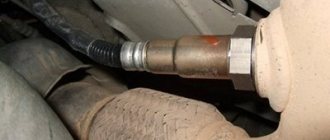
The mechanical difficulty of replacing a lambda probe is unscrewing the coked threaded connection. Here you may have to use special equipment. After removing the faulty sensor, thoroughly wipe the sensor installation area to remove any remaining liquids.
p, blockquote 48,0,0,0,0 –>
Video - replacing the lambda probe on an Audi A4 B5:
p, blockquote 49,0,0,0,0 –>
p, blockquote 50,0,0,0,0 –>
An original lambda probe is usually expensive (up to 6,000 rubles, sometimes more). For some car models, the original sensor cannot be found; it makes no sense to buy it from a disassembly site. In this case, it is better to install a universal lambda probe.
p, blockquote 51,0,0,1,0 –>
Universal lambda probe
The installation dimensions of the sensors (thread, seating depth) are usually the same; it is better, of course, to check so as not to damage the threaded connection or the new probe.
p, blockquote 52,0,0,0,0 –>
Universal lambda probes are sold without a connector, only with wires (usually four wires, two signal and two for the heating element). Next, cut off the connector with wires from the old faulty original sensor and make a high-quality connection with the universal sensor in full accordance with the electrical connection diagram.
p, blockquote 53,0,0,0,0 –> adsp-pro-2 –>
It is better to make the electrical connection using the twisting + soldering + heat shrink insulation method. Since the typical characteristics of all lambda probes made using the same technology are almost identical, universal probes work correctly on engines of all modifications.
p, blockquote 54,0,0,0,0 –>
Video - installing a connector on a universal lambda probe:
p, blockquote 55,0,0,0,0 –>
p, blockquote 56,0,0,0,0 –>
When installing the sensor, pay attention to the tightness of the connection with the manifold and the integrity of the threads. p, blockquote 57,0,0,0,0 –>
p, blockquote 57,0,0,0,0 –>
Briefly about the lambda probe
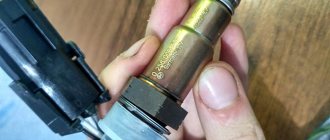
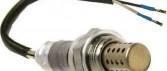
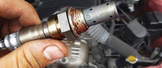
I can assume that the oxygen sensor is perhaps the most popular among all other car sensors that auto repair shop diagnosticians have to deal with. As you can see in the photo, the lambda probe (also known as an oxygen sensor) is made of a ceramic element (zirconium based) and coated with platinum. This galvanic element, depending on the presence of oxygen and temperature in the environment, changes its voltage and transmits data to the electronic control unit. Since the zirconium tip more accurately reads the presence of oxygen at a temperature of at least 360 degrees Celsius, a heating element is built into the lambda probe, which turns on when the engine starts and helps to quickly warm it up.
Oxygen sensor device
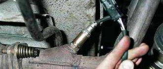
To accurately read the data, the lambda is installed in the exhaust pipe so that its working surface is “washed” by as much exhaust gas as possible.
There are also several types of oxygen sensors, which differ in operating principle and connection method:
Attention! It is possible to replace a heated oxygen sensor instead of a non-heated oxygen sensor. In this case, it will be necessary to connect the LZ heating circuit to the car’s electrical circuit, which is “powered” when the ignition is turned on, for example, the fuel pump circuit. Reverse replacement is not acceptable; this creation will definitely not work. And, of course, it is necessary that the threads of the sensors coincide with the cut threads in the seat.
Principle of operation
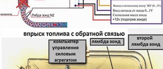
Depending on how much oxygen is in the exhaust gases, the sensor signal going to the electronic control unit also changes. The ECU, in turn, compares the received signal with the standard of this state “stitched” in its memory, and depending on the difference with the optimal value, adjusts the duration injection phases of the injectors, thereby regulating the air-fuel mixture of the engine. With an increased oxygen value, the LZ voltage signal drops to 0.1 volts (which is much lower than the required 0.45); if there is a shortage, its voltage increases to 0.8-0.9 volts. This is a two-way connection with the controller and subsequent adjustment to a specific mode engine operation ensures minimization of atmospheric emissions and maximum fuel economy.
Review of manufacturers, cost of oxygen sensors
| Catalog Article/sensor number | Price, rub.) | Resource (Thousand km) |
| Catalog number of the control sensor 21074-3850010-00 | From 2600 | 70- 75 |
| Diagnostic sensor 2 21074-3850010-00 | From 2600 | 70 — 75 |
| Lambda probe NGK 95801 Code: 0000-749176 | From 2800 - 2900 | 70 — 85 |
| BOSCH 0 258 006537 | —/— | —/— |
| BOSCH 0 258 986 602 | —/— | —/— |
| BOSCH 0 280 218 116 | —/— | —/— |
| BREMI 30223 | —/— | —/— |
| ERA 570023 | —/— | —/— |
| FENOX SD10100O7 | From 3100 – 3300 | —/— |
| FENOX AM28116C3 | —/— | —/— |
| DENSO DOX-0150 | —/— | —/— |
| PIERBURG 7.22701.08.0 | —/— | —/— |
| DENSO DOX-0150 | —/— | —/— |
| STELLOX 20-00028-SX | —/— | —/— |
| STELLOX 20-00022-SX | —/— | —/— |
| STELLOX 20-00020-SX | —/— | —/— |
| PATRON HZ-30301006-0042 | —/— | —/— |
| ERA 570023 | —/— | —/— |
| NGK 5653 | —/— | —/— |
| NGK 1628 | —/— | —/— |
*prices are current as of November 6, 2018.
Diagnostics and replacement of Bosch oxygen sensor 0 258 006 537 on a VAZ-2107i
Today we’ll look at how you can diagnose and replace a faulty lambda probe from Bosch 0 258 006 537 on a VAZ-2107 at home.
First, a little theory:
The oxygen sensor (Lambda probe) is used to determine the level of oxygen content in the exhaust gases; based on its readings, the electronic engine control unit (ECU) regulates the composition and proportions of the fuel-air mixture.
On VAZ cars, zirconium oxygen sensors are the most common. In older modifications (1.5 l.) in Euro-2 systems, the BOSCH 0 258 005 133 sensor was used. In Euro-3 systems it was used as the first DC installed before the catalyst. In new 1.5/1.6 liter cars with the Bosch M7.9.7 and January 7.2 injection system, produced since October 2004, the BOSCH sensor 0 258 006 537 is installed, which will be discussed.
To speed up the warming up of the sensor to operating temperature and quickly start working, it is equipped with an electric heating element. Therefore, the sensor has 4 outputs: two white wires – heater power supply (+12V), black wire – signal (+0.45V), gray – ground.
The ECU constantly supplies a stable reference voltage of 0.45 Volts to the sensor signal circuit, and the heating circuit receives voltage from the on-board network - 12 Volts.
An unheated sensor has a high internal resistance and does not generate its own EMF, so the ECU “sees” only “its” reference voltage. As the sensor warms up while the engine is running (over 360 °C), its internal resistance decreases and it begins to generate its own voltage, proportional to the oxygen content in the exhaust gases.
This voltage overlaps the reference voltage - the ECU “sees” that the sensor has warmed up and its signal is ready to regulate the mixture composition.
Before checking the lambda with instruments, we perform a visual inspection.
First of all, it is necessary to carry out a visual inspection
Pay attention to the sensor connection connectors, the integrity of the wires and the oxygen sensor itself
The following is not allowed:
- Soot. This, as a rule, indicates problems with the lambda heater, as well as that the fuel mixture is over-rich. As a result, in this state, the oxygen sensor becomes clogged with soot, its response worsens, in other words, it begins to “lie and glitch”;
- Shiny deposits. The presence of such deposits is a clear sign of increased lead content in the fuel. Lead damages the probe itself, as well as the catalyst, and is “treated” by completely replacing the lambda;
- White or ashy deposits. Such deposits most often indicate the incorrect use of fuel additives or engine oil that does not match the type of engine. A sensor with such deposits must be replaced.
What is a lambda probe, principle of operation and its types
So, an air sensor is a small device that is installed in the exhaust manifold of any modern car and serves to assess the concentration of residual oxygen in the exhaust gases. Thanks to the readings of this device, the computer unit of your car receives data on the basis of which it prepares a combustible mixture. The lambda probe takes into account the residual oxygen concentration in the burned fuel and sends a signal to the electronics that the newly incoming combustible mixture needs to be either enriched or depleted of air. It goes without saying that any malfunction of the lambda probe may affect the performance of the car’s engine.
Remember! For combustion of 1 kg. mixture of fuel and air, you need to spend about 15 kg . oxygen.
Lambda probe device
A modern air sensor is a small structural device inside which there are a number of interconnected parts.
- A metal body with threads. It is designed to fix the sensor in the mounting hole;
- Insulator made of ceramic;
- O-ring seal;
- Conductors;
- Protective shell with hole for ventilation;
- Contact;
- Ceramic tip;
- Electric heater;
- Gas outlet;
- Steel shell.
As a rule, the start of exhaust gas measurements occurs at a temperature of 310-400 degrees . It is at this temperature that the special filler in the sensor becomes electrically conductive. Until the temperature reaches the desired value, the car’s electronic control unit takes readings from other sensors, and only then from the lambda probe. The peculiarity of its operation is that the exhaust gases and atmospheric air are separated by a container with a current-generating composition. As a result of certain chemical effects on this capacity from the exhaust side and from the air side, a difference in oxygen concentration occurs, on the basis of which an electrical potential is generated. The values of this potential are sent to the vehicle control unit.
All oxygen sensors are divided into four types depending on the number of wires in their design:
1. Single-wire; 2. Two-wire; 3. Three-wire; 4. Four-wire.
All of the above lambda probes come in narrowband and broadband .
Checking the lambda probe with a tester:
We take an electronic constant voltage millivoltmeter and connect it in parallel with the LZ (“+” “-” to the LZ, - to ground), and the lambda probe must be connected to the controller.
When the engine warms up (5-10 minutes), then you need to look at the voltmeter needle. It should periodically move between 0.2 and 0.8 V (i.e. 200 and 800 mV, and if less than 8 cycles occur in 10 seconds, it’s time to change the LZ. Also replace if the voltage “stands” at 0 .45 V.
When the voltage is always 0.2 or 0.9 V, then there is something wrong with the injection - the mixture is too lean or too rich. Since the oxygen sensor voltage should change all the time and jump from ≈0.2 to 0.9V.
There is another quick way to check the lambda probe. You should do this:
Carefully pierce the positive contact of the tester (black lambda wire), the other contact to ground. With the engine running, the readings should range from 0.1 to 0.9V. Constant readings (for example, 0.2 all the time) or readings that go beyond this range, or fluctuations with a smaller amplitude indicate a malfunction of the probe.
- all the time 0.1 - little oxygen
- all the time 0.9 - a lot of oxygen
- The probe is fine, the problem is something else.
If you have the time and desire to bother, you can conduct several tests for a rich and lean mixture and additionally check the lambda probe.
- Disconnect the oxygen sensor from the block and connect it to a digital voltmeter. Start the car and, by pressing the gas pedal, increase the engine speed to 2500 rpm. Using a device for enriching the fuel mixture, reduce the speed to 200 per minute.
- If your vehicle is equipped with an electronically controlled fuel system, remove the vacuum tube from the fuel pressure regulator. Look at the voltmeter reading. If the instrument needle approaches the 0.9 V mark, it means the lambda probe is in working condition. A malfunction of the sensor is indicated by the lack of response from the voltmeter, and its readings are less than 0.8 V.
- Do a lean mixture test. To do this, take a vacuum tube and provoke an air leak. If the oxygen sensor is working properly, the digital voltmeter reading will be 0.2 V or lower.
- Check the operation of the lambda probe in dynamics. To do this, connect the sensor to the connector of the fuel supply system, and install a voltmeter parallel to it. Increase engine speed to 1500 rpm. The voltmeter readings with a working sensor should be at the level of 0.5 V. Another value indicates a failure of the lambda probe.
Checking the voltage in the heating circuit
To check the presence of voltage in the circuit, you need a voltmeter. We turn on the ignition and connect it with probes to the heater wires (you cannot disconnect the connector, it is better to pierce it with sharp needles). Their voltage should be equal to what the battery produces when the engine is not running (about 12V).
If there is no plus, you need to go through the battery-fuse-sensor circuit, since it always goes directly, but the minus comes from the ECU, so if there is no minus, look at the circuit to the block.
Checking the lambda probe heater
In addition to measuring voltages with a multimeter, you can also measure resistances to check the serviceability of the heater (two white wires), but you will need to switch the tester to Ohms. The documentation for a particular sensor must indicate the nominal resistance (usually it is about 2-10 Ohms), your task is only to check it and draw a conclusion. The video shows this method:
https://youtube.com/watch?v=CxhGVt5_YUA
Checking the oxygen sensor reference voltage
We switch the tester to voltmeter mode, then turn on the ignition and measure the voltage between the signal and ground wires. In most cases, the lambda probe reference voltage should be 0.45V.
Most zirconium lambda probes, which are installed on cars starting from 1999, have the same color differentiation of zirconium sensors. The same is with lambda probes produced using titanium alloys - their pinouts correspond to the same values shown in the table. There is only one difference - there are a lot of cars with zirconium-based lambda probes, titanium ones are rare, but still found. Determining the purpose of each lambda probe contact can be determined using special tables that will be presented below.
If the color combination of your sensor is identical to the color combination of one of the columns of the tables below (zirconium or titanium lambdas), then the sensor has the specified design and the pinout of the 4-wire lambda probe corresponds to the data indicated in the table.
Checking the sensor power (voltage at the oxygen sensor)
Before replacing the sensor, you need to make sure that it is receiving power and that all circuits are working properly. To do this, open the hood and disconnect the sensor connector (it is attached with a clamp to the cooling system pipe).
- Check the heating element circuit. We take the tester and connect its “minus” to the engine, and attach the “plus” to contact “B”. Turn on the ignition and look at the tester readings: it should show 12V. If the tester readings are less than 12V or are absent at all, then either the battery is discharged (which is unlikely) or the power circuit is open (we eliminate the malfunction). The ECU may also be faulty, but as a rule, the on-board computer immediately indicates this error.
- We check the circuit of the sensitive element. We measure the voltage between contacts “A” and “C”. minus on "C" plus on "A". The voltage should be 0.45V. If the voltage is absent or differs by 0.02 V or more, then the power circuit is faulty (you need to find and fix it) or the ECU is faulty (which is also unlikely).
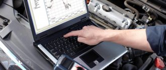
You can fully check the sensor for functionality only with the help of an oscilloscope, which most car enthusiasts do not have, so I see no point in describing this situation. I will only say that to check it you will need to artificially lean and enrich the fuel mixture and look at the sensor readings.
If the sensor has already traveled quite a bit - more than 100,000 km, then it can be safely replaced. Because, even if it is working, the sensitivity has noticeably deteriorated - which leads to extra costs for gasoline.
There are so-called “lambda probe simulators”. I’ll say right away that they will not fit our cars, because... The ECU does not read their signals.
You must clearly understand the operating principle of the sensor. Please note the following errors
| Error P0131 | Low signal level of oxygen sensor 1 |
| Error P0132 | Crankshaft sensor 1 signal high |
A low sensor signal means the mixture is too rich.
A high sensor level indicates that the mixture is too lean.
Please note that these errors indicate the state of the fuel mixture and do not indicate a sensor malfunction. Therefore, when these errors occur, you first need to look at the fuel pressure and the presence of air leaks in the intake system, and only then pay attention to the sensor itself. Home page
How to change an oxygen sensor
The dismantling procedure does not apply to scheduled repair work and is usually performed as necessary; however, experts still make certain recommendations:
- It is better to change planar sensors every 160,000 km;
- with heating - every 100,000 km;
- without heating - every 50,000 - 80,000 km.
Replacement begins by removing the part protection and treating the retaining nut with WD-40 or a similar compound. The engine must not be overheated to avoid manifold expansion. Installation procedure:
- Using a screwdriver, disconnect the connectors of each wire;
- Use a special key with a slot to unscrew and remove the probe (if it does not unscrew, the threads can be lubricated with WD-40, but carefully so that the composition does not get on other parts);
- Install a new sensor, trying to avoid distortions, tighten the fastening;
- Reconnect the connectors and install protection;
- If you are also replacing 2 lambda probes, then do the same with the second device (there may be two or more).
After this, you need to check the functionality of the system. There should be no errors displayed on the dashboard and the engine should run stably
It is also important to ensure that the connection between the new part and the engine controller is correct. To do this, different types of driving are launched, laid down by the car manufacturer.
If no problems appear, then the procedure was completed successfully.
Quite often there are cases when a car mechanic changed the lambda probe on his own, but this did not give the desired result. Therefore, we always recommend contacting professionals at a specialized car service center. Our car service technicians can quickly and efficiently replace the oxygen sensor so that your car always works as it did after it came off the production line. Don’t delay if problems arise, because the principle is known: the earlier a breakdown is detected, the easier and cheaper it is to fix it. If you need to replace a lambda probe in St. Petersburg, call us at the number indicated on the website.
Posts 6
1 Topic by serega 32 2014-11-30 00:15:08
- serega 32
- New member
- Inactive
- Registration: 2014-11-29
- Messages: 5 Thanks : 0
- Car: VAZ 2109i
Topic: oxygen sensor connector is broken, how to connect by color? VAZ 2109
The connector has come off. How can I now connect the wires without this connector? Which wire goes to which? they are not there by color. Tell me who has encountered this!?
Added: 2014-11-30 01:15:08
I forgot to say, the car is a VAZ 2109i
2 Reply from Serg 2014-11-30 08:52:53 (2014-11-30 08:59:27 edited by Serg)
- Serg
- Lada2111.rf fan
- Inactive
- Registration: 2013-07-29
- Messages: 830 Thanks : 363
- Car: 2111 dwg 2114 year 2008
Re: oxygen sensor connector is broken, how to connect by color? VAZ 2109
Which side did the sensor or harness come off from? The connector has the letters ABCD
sensor A – C sensor output (gray and black) B – D sensor heater (usually white wires)
harness A – pink to ECU 28 leg B – pink/black +12V heater power supply C – red/white to ECU 10 leg D – white/black to ECU
3 Reply from serega 32 2014-11-30 11:41:24
- serega 32
- New member
- Inactive
- Registration: 2014-11-29
- Messages: 5 Thanks : 0
- Car: VAZ 2109i
Re: oxygen sensor connector is broken, how to connect by color? VAZ 2109
Thank you. only there is no connector itself, just wires hanging. 4 from the sensor and 4 from the harness.
Publication date: January 16, 2022. Category: Automotive equipment.
Lambda probe (also called oxygen controller, O2 sensor, DC) is an integral part of the exhaust system of vehicles that meet EURO-4 environmental standards and higher. This miniature device (usually 2 or more lambda probes are installed) monitors the O2 content in vehicle exhaust mixtures, thereby significantly reducing the emission of toxic waste into the atmosphere.
If the DC is not operating correctly or if the lambda probe is disconnected, the functioning of the power unit may be disrupted, causing the engine to go into emergency mode (the Check Engine light will light up on the panel). To prevent this from happening, the car system can be outsmarted by installing a decoy.
Description and device
For the sensor to work normally, it must have a temperature of at least 300°, so after the engine starts, it is heated by the built-in thermal element. Please note that when using leaded gasoline, poisoning of the oxygen sensor may occur. This is also possible when the factory seals the engine with silicone sealants that release volatile substances.
Their presence can damage the device and negatively affect the operation of the motor itself if it enters the combustion chamber. The engine controller reacts to this by writing an error message to the ECU memory. The first oxygen sensors were heated only by exhaust gases. The name “lambda probe” is also found. On automobile forums, many pages have long been written on the topic of what a lambda probe is and what malfunctions it has.
Lambda is exactly the thing that mechanics and diagnosticians encounter most often. The easiest way to diagnose a UDC is to measure the voltage at the signal output. If it does not exceed 0.45 V, this means that the probe is working properly. A particular danger to the normal operation of the oxygen sensor is the soot deposited on it when the engine runs on an over-enriched mixture.
The sensor is located in a special hole in the exhaust manifold on a thread very close to the cylinder block. With a faulty oxygen sensor, you will not be able to legally pass a scheduled technical inspection. The car will be sent for repairs, and the ECU will put it into emergency mode, in which it will not deliver its full power potential.
The frequency of replacing a lambda probe with a new one is on average 50,000 km. That is, after the first 50,000 mileage and beyond. The number of probes on a modern car can reach 4 (on Kalina there are usually two). Based on the number of contacts available, the oxygen sensor can be:
- single-contact;
- two-pin;
- three- and four-pin.
The quality of the fuel, namely the presence of organometallic additives in it, directly affects the accuracy of lambda readings. These additives are the most dangerous pollutants for the oxygen sensor when forming exhaust gases.
Symptoms of a problem
The main symptoms of a failed lambda probe are frequent engine overheating, the use of poor quality fuel, moisture or coolant ingress, the accumulation of large amounts of soot on it, as well as depletion of resource capabilities.
A faulty oxygen sensor 2110 leads to incorrect operation of the entire engine.
Signs of its malfunction or incorrect operation are:
- jerking of the car during acceleration;
- Unstable engine operation at idle (independent increase or decrease in the number of revolutions);
- increased fuel consumption;
- engine overheating;
- sudden stop of the engine after acceleration or revving;
- reduction in vehicle traction capabilities;
- increased toxicity of exhaust gases, changes in color, density and odor;
- The Check Engine light on the dashboard came on.
How to repair a lambda probe
Repairing a lambda probe with your own hands is quite simple; to do this, you need to determine in which particular unit the failure occurred.
If the problem is related to the circuit contacts, then first of all you need to find the break point and check whether the contacts have oxidized. The signal may simply not come from the control unit. Therefore, check the lambda power supply. If the element contacts have oxidized, they must be treated with WD40.
We recommend: How to properly put covers on car seats - simple instructions for drivers
If a lot of carbon deposits have formed on the probe body, it may be necessary to clean all parts of the system. And here a natural question arises: how to rinse the lambda probe. The fact is that it is strictly prohibited to process platinum electrodes and ceramic rods with sandpaper. Therefore, it is necessary to use specialized products designed to dissolve rust.
To clean the sensor, follow these steps:
- Remove the lambda probe after heating its housing to 50 degrees.
- Remove the protective cap.
- Soak the sensor in phosphoric acid for 30 minutes (it will cope with even the most difficult deposits).
- Rinse the lambda in water, dry it and install the element back. Don't forget to lubricate the sensor threads with a special agent to create a complete seal (but don't use silicone sealant).
Since the cost of sensors ranges from 1000 - 3000 rubles per element, it is quite reasonable to try to repair the lambda probe yourself (see video below), and only then proceed to install a new element.
Reading errors
Checking the VAZ 2114 oxygen sensor may be limited to simply reading errors from the board, here are the most common ones related to lambda:
- Error P0131 is a problem with the signal level coming from the device; it is too low, indicating that the mixture is concentrated.
- Error P0132 is a similar problem with the signal, only in the case of errors, the signal is high, indicating a lean fuel mixture.
The errors issued are not a panacea; they relate more to the fuel system, and not to fixing problems with the lambda probe. Therefore, we saw errors - look at what’s wrong with the fuel pressure indicator and whether there is any air leakage from the atmosphere. Then do diagnostics of the sensor itself.
The voltage on the oxygen sensor is one of the stages of checking its functionality. Before replacing or repairing a lambda probe with your own hands, you need to carefully check whether the device is receiving the necessary power and what the condition of the contact circuits is. To do this process, you need to open the hood of your fourteenth and remove the sensor (its connector is secured with a small clamp on the cooling system pipe). We will look at two circuits - the heating element of the device and the oxygen reading element on the sensor body.
- To look at the circuit of the heating element, you need to take a multimeter, connect its negative terminal to the engine, and the positive terminal to wire B. Turn the key in the ignition, look at the numbers on the multimeter: if 12 V, then good, less - this is a discharged battery (in a rare case ), open circuit of contacts (most likely). Another option is to blame the electronic control unit, but here the on-board computer usually gives an error.
- To check the circuit of the sensitive element, you need to measure the voltage between wires A and C. We put the negative terminal of the multimeter on wire C, the positive terminal on wire A. We look at the indicator on the screen: if 0.45 V, then everything is in order. If there is no number or it fluctuates within 0.02 V, the problem is in the power circuit. Again, the option is to blame the ECU, but it is not common.
Resource consumption of the oxygen sensor
The manufacturer, in its recommendations, encourages owners of practical Lada Kalinas to resort to replacing the sensor after a mileage interval of 80-160 thousand km. If the driver detects the presence of the first signs of a malfunction of the component we are considering, then the repair operation will need to be carried out before the indicated mileage.
Experts include the following main signs indicating that the lambda probe has become unusable:
- unauthorized increased fuel consumption of the vehicle;
- lack of stability in idle speed;
- deterioration of dynamic and speed capabilities.
Note that the quality indicator of the fuel can have a significant impact on the condition and service life of the probe. Here, for the purpose of prevention, you should check the gasoline supplier by changing the gas station and then comparing the behavior of the car.
Roof rails for Lada Granta
What are the best spark plugs for Lada Granta 8 valve
Lada Granta replacement lamp for running lights
To create convenience when replacing a sensor, the manufacturer has developed an entire system that includes a diagnostic process. To do this you will need to use a special scanner. If the LADA Kalina car has an on-board controller, then the entire list of errors that appeared in the probe can be seen on the display broadcasting the diagnostic mode. For example, an error code of “PO130” indicates an inadequate signal sent by the oxygen sensor, and an error code of “PO135” will indicate a breakdown of the heating component. By the way, the entire list of error codes can be found on the Internet or in the instructions included with the car.
Electronic snag
Another way to eliminate problems with the DC is to use an electronic decoy of the lambda probe, the diagram of which is presented below. Since the oxygen sensor transmits a signal to the controller, a decoy circuit connected to the wiring from the sensor to the connector will “crude” the system. Thanks to this, in a situation where the lambda probe is faulty, the power unit will continue to operate correctly.
Healthy! The installation locations for such deception may differ depending on the PBX model. For example, it can be mounted in the central tunnel between the seats, in the dashboard or in the engine compartment.
The decoy circuit is a single-chip microprocessor that analyzes the processes in the catalyst, receives data from the first DC, processes it, converts it to the indicators of the second sensor and issues a corresponding signal to the car processor.
Oxygen sensor for Lada Priora: original, analogues, price, catalog numbers
Despite the fact that the price of the original controller is slightly higher than 1,500 rubles, not many car enthusiasts are willing to buy factory spare parts. Cheap analogues are often preferred.
So-called “fake devices” are installed instead of standard sensors. After 90 - 100 thousand km. The Lada Priora catalyst becomes unusable, as evidenced by a number of signs. At the request of the client, the service station technicians remove (cut out) the standard catalyst from the exhaust system and replace it with a “dummy”.
Dummy exhaust manifolds are made according to the scheme: 4-2-2 or 4-2. Popularly called spiders. This is a one-piece design together with the exhaust manifold coupling and exhaust pipe.
To prevent the electronic control unit from identifying a system error, the lambda probe is replaced with one of the following types of decoys:
- Mechanical;
- Electronic.
Types of sensors and operating principle
The lambda probe is installed in the exhaust system. Sensors are divided into two types: two-point and broadband.
The two-point sensor consists of ceramics, the elements of which are coated with zirconium dioxide on both sides. Installed in front of or behind the catalytic converter.
The principle of operation is to measure the level of oxygen concentration in the environment and exhaust gases. If the level changes and becomes different, a voltage is created at the ends of the sensor elements, from low to high. Low voltage is created if there is excess oxygen in the system.
Otherwise, if the system does not have the required level of oxygen, high voltage will be created. These signals are sent to the engine control unit, which distinguishes them by current strength.
The wideband sensor is a more modern design. It also has two ceramic elements. One of them can be called “pumping”. It is responsible for activating the process of pumping or removing air from the system.
The second element can be conventionally called “two-point”. The principle of operation is based on the fact that as long as there is the required amount of oxygen in the mixture, the current strength on the “pumping” element does not change and is transferred to the “two-point” element.
It, in turn, receiving a constant current from the “pumping” element, maintains a constant voltage between its elements and is inactive.
As soon as the oxygen level changes, the "pumping" element supplies the changed voltage to the "two-point". This, in turn, ensures either pumping air into the system or pumping it back.
How to troubleshoot an oxygen sensor?
There is no ideal technology for repairing lambda probes. If a breakdown occurs, the part should be completely replaced. Of course, there are some methods for restoring oxygen, but it does not always work. Most often, the sensor stops working due to the appearance of carbon deposits on the tip. If the deposits are removed, the sensor begins to work correctly.
First method
The protective cap should be removed by cutting a file into the base of the device. If that doesn’t work, you can make several small 5mm holes. I note that after cleaning, the protective cap must be secured back using argon welding. When installing the sensor, the threads must be lubricated with thermal paste, avoiding its contact with the sensitive tip.
Cleaning procedure:
- Place 100 ml of orthophosphoric acid in a glass container.
- Carefully place the tip into the acid. The entire sensor cannot be placed in a container! Wait about 20 minutes, during which time phosphoric acid will be able to remove carbon deposits.
- Then the sensor must be washed with water and dried.
It happens that it will not be possible to remove deposits the first time, so you will have to perform many procedures. If this does not help, then you need to clean it with an unnecessary toothbrush.
Second method
The carbon deposits on the oxygen sensor are burning off. In addition to phosphoric acid, you will need a gas burner (or a regular gas stove).
- Soak the probe tip in phosphoric acid.
- Carefully take the sensor from the other side with pliers and bring it to the gas burner.
- The phosphoric acid at the tip will boil, forming a green salt. Along with the salt, carbon deposits will also be removed.
- It is necessary to repeat this procedure as many times as possible until the soot is completely gone and the sensor becomes shiny.
What are the consequences after installing decoys?
You need to understand that any deception is installed at the risk of the car owner. If the installation was carried out incorrectly, you may encounter the following problems:
- Due to the fact that the on-board computer cannot regulate fluid injection, engine malfunction may occur.
- If the circuit is not properly soldered, it may damage the wiring.
- In the process of installing the decoy, you can damage the oxygen sensors, after which you will not even know about their malfunction (since you will already have the decoy installed).
- After such interventions (not only during flashing), the on-board computer may fail.
Any inaccuracy will lead to disastrous consequences, so it is better to install a safer ready-made emulator. Unlike deception, it does not “deceive” the control unit, but only ensures its correct operation by converting the DC signal. A microprocessor is also installed inside the emulator (as in a homemade electronic decoy), which is capable of assessing exhaust gases and analyzing the situation.
Replacing and checking the oxygen concentration sensor on LADA
The oxygen sensor (lambda probe or DC) determines the amount of free oxygen remaining in the exhaust gases. Based on its data, the electronic engine control unit adjusts the composition of the fuel-air mixture. Let's look at the features of replacing and checking the oxygen sensor on LADA cars.
Where is the oxygen sensor located? Control and diagnostic oxygen concentration sensors are installed in the exhaust system of LADA cars.
Signs of a malfunctioning oxygen sensor:
- high fuel consumption;
- floating engine idle speed;
- the car accelerates poorly;
- etc.
Catalog number (article) DK:
- Lada Vesta and XRAY - 226А41772R
- Lada Priora/Kalina/Niva 4x4 — 11180-3850010-00
- Lada Granta/Kalina 2 - 21074-3850010-00
- Lada Largus - 8201071311, 8200632270 and 6001549061
Replacing oxygen sensors. To avoid burns, we begin work after the exhaust system has cooled. Before unscrewing the sensors, disconnect the block with the wires (press the latch).
- To remove the upper oxygen sensor, you will need a 22 key.
- To unscrew the lower sensor, you will need an inspection ditch and a special “22” socket, or you can cut off the handle of a regular “22” open-end wrench.
If necessary, treat the sensor connection with lubricant.
Installation in reverse order. If the sensor is being reused, treat the threads with a special mounting paste, avoiding contact with the protective tube. Because the sensor draws reference air through the housing, it cannot be treated with contact spray or lubricant.
Checking the oxygen sensor (both sensors are checked in the same way). The easiest way is to replace the sensor with a known good one.
- Check the supply voltage of the heating element. We connect the “negative” probe of the voltmeter (the multimeter is in engine voltage mode, and the other to terminal B or No. 4. The voltage at the terminal must be at least 12 V. If it is not there or it is less than 12 V, then the battery, power circuit or ECU is discharged .
- We check the voltage between terminals A and C or 1 and 2 (we connect the negative probe to terminal C or 1). The voltage should be 0.45 V. If it is not there or it differs by more than 0.02 V, then the power circuit or the ECU is faulty.
If the oxygen sensor is faulty, it is replaced with a new one. In some cases, you can try to restore it. Have you ever had to change or check the lambda probe yourself? What difficulties have you encountered?
Symptoms of malfunction
Where is it installed?
Based on the behavior of the car, you can easily determine that the lambda probe has become unusable:
- The car jerks while driving;
- The revolutions are floating;
- The catalyst is not working properly;
- Fuel consumption increases noticeably;
- Exhaust gases contain a large amount of toxins.
How to make a corrector (fake) lambda probe?
There are several types of correctors for oxygen controllers. The mechanical device is the simplest and most affordable in terms of corrector design. It is necessary to machine a special adapter into which the lambda probe is installed, as well as a mini-catalyst. After this, the assembled device is mounted in the standard place of the car muffler.
If the catalyst device or the oxygen sensor installed after it breaks down, a signal will be sent to the control unit. The module will be warned that the exhaust gases contain harmful substances, the volume of which exceeds the permissible value. The control unit will perceive this event as an emergency and increase the fuel supply to enrich the air-fuel mixture.
When installing such a corrector, exhaust gases will flow through a small hole in the adapter into the catalyst device. The latter is filled with ceramic dust with a catalytic layer. The concentration of harmful substances in the exhaust gases will be lower. The control module will perceive this as the correct operation of the controller and standard catalyst device. The manufacture of blende is carried out using a lathe and a diagram; steel or bronze can be used as a material.
Scheme of a mechanical corrector for a lambda probe
Universal drawings that can be found on the Internet may not be suitable for making a lambda probe blende for a specific car model; you need to look for a proven option.
Making an electronic controller fake:
- Using the SprintLayout program and a printer, a layout drawing and arrangement of circuit elements are printed. Printing is done on glossy paper.
- When sending a file for printing, you must select 100% black for layer K1. In the program, check the box next to Mirror and Scheme Outline. All other layers are deleted.
- Then the next layer is sent for printing. For the M2 layer, the color is black. The checkbox opposite the Mirror item is removed, but it remains opposite the second element. Other layers are removed.
- When performing the task, it is recommended to use foil textolite. It must be one-sided, and its thickness will be no less than 1 and no more than 2 mm.
- When the printout is in hand, it must be transferred to the LM324 board using an iron. The board itself is cut out taking into account the dimensions, and printouts must be made along its contour. After cutting, attach the diagram to the drawing; the dimensions must match exactly.
- Using fine-grained sandpaper, the copper layer is cleaned. The board is cleaned using fuel or solvent.
- Then you need to transfer the printout with the tracks to the working surface of the board. A printed layer of elements is installed on the reverse (copper surface). To do this, foil paper is applied to the board and heated with an iron; the procedure takes no more than 10 minutes. When warming up, the surface of the iron should be pressed as close as possible to the board. As a result, the toner should be reprinted from the foil surface onto the circuit. If the paper density is low, the tracks will be visible. The problem can be corrected using a permanent black marker.
- The next step will be etching, this will require ferric chloride or sodium perchlorate.
- Then holes are drilled on the board and the elements are soldered.
- At the final stage, the operating parameters of the corrector are adjusted. To do this, +950 mV is supplied to the input, and the voltage value is adjusted in the range from 950 to 1000 mV. For the LM324 board, the procedure is done by setting up elements VR3 and VR4.
How to check the lambda probe on a VAZ 2114 as quickly as possible
In order not to delay this process, you should understand the design of the device.
- One of the main parts of the sensor is the protective tips (shielded), which can be found on both sides of the electrolyte. It is on them that the holes for exhaust gases are located. These holes can also be used for air intake. It is the tips that are the main functional part of the device. From them, the device can determine the potential difference.
- A collector is located inside the tips. It is also called an element having high current conductivity.
- Between the tips there is a special device that reads the electrical signal.
- You should also understand the purpose of the wires. White wires are needed to power the device. One of the black wires is used to transmit data to the ECU, and the other is needed for grounding.
DC REPLACEMENT TECHNOLOGY
To change the VAZ 2114 oxygen sensor yourself, you will need open-end wrenches 22 and 17, wire cutters, any liquid for dissolving rust, the same VD40 is perfect, as well as plastic clamps.
How the oxygen sensor will be replaced depends on the displacement of your car, since on the VAZ-2114 with 1.5 and 1.6 liter engines the DC is located in different places.
On fourteenths with a one and a half liter power unit, the DC is located on the intake manifold of the exhaust pipe, and you can only get to it by driving the car into a repair pit or overpass. Therefore, take care in advance of a place where you will be comfortable working.
Position of the oxygen sensor on a VAZ 2114 with a 1.5 l engine
The fourteenth with a 1.6 liter engine have better access to the oxygen sensor. It is located in the engine compartment, on the exhaust manifold housing. Moreover, on the VAZ-2114 1.6 liter, the engine of which complies with the Euro-3 standard, two DCs are installed (on old Euro-2 engines - one). And if you need to replace the lambda probe, you must first determine which sensor is faulty.
Position of the DC on a VAZ 2114 with a 1.6 engine (Euro -3)
And so, if you need to change the oxygen sensor of a VAZ 2114, follow the following algorithm of actions:
- We drive the car into the repair pit (if you have a 1.5L engine). Open the hood and remove power from the battery;
- We determine the power wires that go to the DC; they are secured with plastic clamps to the cooling system pipe. The clamps must be cut using wire cutters and the wire block disconnected;
- Next you need to disconnect the sensor. It is fixed in the mounting socket with one 22-diameter nut (or 17 mm on 1.6 engines), which can be unscrewed with a wrench of the appropriate size.
Unscrewing the oxygen sensor is simple only in theory, but in practice you will most likely encounter the fact that the fixing nut and the thread on the manifold body are firmly stuck to each other.
If this problem prevents you from removing the oxygen sensor, the threaded connection must be thoroughly treated with WD-40 or any other chemical rust solvent, wait 5-10 minutes, and then make repeated attempts to unscrew the nut.
If chemical treatment does not produce results, you need to resort to more severe methods. To begin, connect power to the battery and start the car. Let the engine idle for a while so that the manifold and the DC itself warm up a little. Next, put on protective gloves and try to unscrew the thread.
How to unscrew the lambda probe if this does not help? There is only one option left - “thermal shock”. You will need a gas torch or a blowtorch, which needs to warm up the threaded connection well, after which it needs to be cooled sharply with cold water.
When strongly heated, the metal will expand, and when cooled sharply, it will contract, as a result of which all the plaque will peel off and the connection will weaken. As you understand, it will not be possible to carefully remove the DC when using this method - even a normally functioning device after this is 100% likely to completely lose its functionality, so do this only as a last resort.
Once the thread has yielded to you, install the new sensor into the socket, tighten the connection (do not overdo it so as not to damage the device body) and connect power to the sensor. Use plastic clamps to secure the wiring to the cooling system pipe.
Now you know how to replace the lambda probe of a VAZ 2114. Good luck with your driving without breakdowns!
Replacement
Connection wire
Replacing the lambda probe is not at all difficult. The main thing here is to find a device identical to the old one. For this purpose, the sensors have corresponding markings, by which you can easily find an analogue.
- Wait until the engine cools down completely. Make sure the ignition is turned off;
- The old sensor is dismantled with a regular wrench. Just before this, be sure to disconnect the wires going to the lambda probe;
- Next, a new device is installed;
- The new sensor should be screwed in carefully, since excessive force on the wrench may cause the thread to break;
- Reconnect the wires and check the new probe in operation.
As you can see, checking and replacing the oxygen sensor on the VAZ 2110 is quite simple. You don't have to be a professional. Follow the instructions and only use a similar probe, as a device with a different marking simply will not function.
Methods for diagnosing an oxygen sensor
Experts advise checking the correct operation of the lambda probe every 10,000 km, even if there are no problems with the operation of the device.
Diagnostics begins with checking the reliability of the connection between the terminal and the sensor and for the presence of mechanical damage. Next, unscrew the lambda probe from the manifold and inspect the protective casing. Small deposits are cleaned.
If, during a visual inspection, traces of soot, strong white, gray or shiny deposits were detected on the protective tube of the oxygen sensor, the lambda probe should be replaced
How to check a lambda probe with a multimeter (tester)
The sensor is checked for functionality using the following parameters:
- Heating circuit voltage;
- "Reference" voltage;
- Heater condition;
- Sensor signal.
Connection diagram to the lambda probe depending on its type
The presence of voltage in the heating circuit is determined with a multimeter or voltmeter in the following sequence:
- Without removing the connector from the sensor, turn on the ignition.
- The probes are connected to the heating circuit.
- The readings on the device must match the voltage on the battery - 12V.
“+” goes to the sensor from the battery through the fuse. In its absence, this circuit is called.
“—” comes from the control unit. If it is not detected, check the terminals of the lambda probe - ECU circuit.
The reference voltage measurements are carried out using the same devices. Sequencing:
- Turn on the ignition.
- Measure the voltage between the signal wire and ground.
- The device should show 0.45 V.
To check the heater, set the multimeter to ohmmeter mode. Diagnostic stages:
- Remove the connector from the device.
- Measure the resistance between the heater contacts.
- The readings on different oxygen pumps are different, but should not go beyond 2-10 ohms.
A voltmeter or multimeter is used to check the sensor signal. For this:
- They start the engine.
- Warm it up to operating temperature.
- The probes of the device are connected to the signal wire and the ground wire.
- Engine speed is increased to 3000 rpm.
- Monitor voltage measurements. Jumps should be observed in the range from 0.1 V to 0.9 V.
If during at least one of the checks the indicators differ from the norm, the sensor is faulty and needs to be replaced.
Video: checking the lambda probe with a tester
Checking with an oscilloscope
The main advantage of this lambda probe diagnostic over checking with a voltmeter and multimeter is the recording of the time between similar changes in the output voltage. It should not exceed 120 ms.
- The probe of the device is connected to the signal wire.
- The engine is warmed up to operating temperature.
- Engine speed is increased to 2000-2600 rpm.
- Based on the oscilloscope readings, the performance of the oxygen sensor is determined.
Diagnostics with an oscilloscope gives the most complete picture of the operation of the lambda probe
Exceeding the time indicator or crossing the voltage limits of the lower 0.1 V and upper 0.9 V indicates a faulty oxygen sensor.
Video: diagnosing an oxygen sensor with an oscilloscope
Other verification methods
If the car has an on-board system, then the “CHECK ENGINE” signal, which generates a certain error, can be used to diagnose the condition of the lambda probe.
List of lambda probe errors
In order for the lambda probe to work for a long time and efficiently, it is necessary to fill the car only with high-quality fuel. Scheduled and timely diagnostics of the oxygen sensor will help to detect its malfunction in time. This measure can extend the life of not only the sensor itself, but also the catalyst.
Repair
Diagnostics
The VAZ 2110 lambda probe has four outputs:
Pads for VAZ 21102
Checking the oxygen sensor heater comes down to a basic check of the heater circuit:
In the future, we are exclusively interested in the signal wire, or rather, the change in voltage passing along it from the sensor to the ECU during various engine operating modes. You can check the operation of the sensor in two ways:
- Using a voltmeter;
- Using an oscilloscope (motor tester).
Since this instruction is intended for the common man who simply cannot have professional equipment in principle, we will diagnose the sensor using a voltmeter.
Method one: reading trouble codes
In order to read the fault codes located in the controller’s memory, it is necessary to either connect special diagnostic equipment to the diagnostic block (located on the left side under the instrument panel console) (too simple - not for us), or close contact “B” to ground, which is so The same can be done by connecting contacts “A” and “B”.
Diagnostic block VAZ 2110
- “A” - contact connected to the vehicle ground;
- “B”—controller signal contact;
- “G” — control of the VAZ fuel pump;
- “M” is a contact for issuing information (serial data).
After these contacts are closed, turn the ignition key to position “III” (do not start the engine), observe the “CHECK” indicator, which should flash the number 12:
- Flash;
- 1-2 second pause;
- Flash;
- Flash;
- Long pause of 2-3 seconds;
- Double repetition of the above cycle.
Reading fault code number “12”
Attention! This code indicates that the self-diagnosis program is running, otherwise this program does not work.
After this, the program displays codes of existing faults in a triple cycle (each code three times), in the absence of these, code “12” continues to be displayed constantly.
Attention! When the diagnosis is completed, these contacts are allowed to be opened only after the ignition is turned off, after ten seconds.
Erasing fault codes from the ECU memory in order to make sure that the fault has been eliminated occurs by turning off the controller's power for at least ten seconds. The power is turned off either by disconnecting the negative terminal from the battery or by removing the controller fuse.
The main causes of lambda probe malfunctions and the consequences of its breakdown
Once we have defined the concept and operating features of the oxygen sensor, we can conclude that it plays a key function in the normal operation of the internal combustion engine. So what can cause the lambda probe to break down and fail? There are two aspects to this issue: external factors and internal ones, about which read below.
- Coolant or brake fluid leaking into the sensor housing;
- Caring for the sensor with means that are not intended for such purposes;
- Poor quality fuel with excessive lead content;
- Overheating of the sensor, which also happens when using bad fuel.