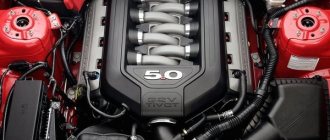
The car engine power system is designed to supply, purify and store fuel, purify air, produce a combustible mixture and launch it into the engine cylinders. The quality and volume of this mixture must be different under different engine operating modes, which is also the responsibility of the engine power system. Since we will consider the operation of gasoline engines, our fuel will always be gasoline. Depending on the type of device that prepares the air-fuel mixture, power units can be carburetor, injection, or equipped with single injection. To ensure economical and reliable operation of the engine, gasoline must have sufficient detonation resistance and good volatility.
Detonation (see engine detonation) is the very rapid combustion of fuel, similar to an explosion. Operating the engine with detonation is unacceptable, because is accompanied by shock load on the piston pins, main and connecting rod bearings, local heating of components, smoky exhaust, burnout of valves and pistons, increased fuel consumption, and decreased engine power. The occurrence of detonation is also affected by the load and speed of the engine, ignition timing, carbon deposits on the cylinder head and piston (see piston operation). The anti-knock properties of gasoline fuel are assessed by octane value. Gasoline is compared with a mixture of the following fuels: isooctane, heptane. Heptane detonates strongly - because of this, its octane number is conventionally assumed to be zero. The second fuel, isooctane, weakly detonates - its octane number is conventionally taken to be 100 units.
The octane number of a fuel is the percentage of isooctane in a mixture with heptane that is equivalent in its knock resistance to the fuel used. For example, if a mixture consisting of 24% heptane and 76% isooctane (by volume) corresponds to the tested gasoline fuel in terms of detonation qualities, then the octane number of this gasoline will be equal to 76. The higher the octane number of the fuel, the higher its resistance to detonation.
In general, the fuel system consists of the following elements:
- fuel tank (it stores a supply of fuel - gasoline or diesel fuel)
- fuel pump (takes fuel from the tank and sends it to the engine)
- Fuel level sensor (signals when refueling is required)
- fuel filter or filter system (clean fuel from mechanical impurities)
- air filter (cleanses the air of dust and other small particles)
- fuel line (a system of tubes and hoses that carries fuel to the engine)
- injection system (the device through which fuel enters the combustion chamber)
The fuel tank, or gas tank, is a metal or plastic container that is usually located under the trunk, although some cars have found some interesting places for it. If you cannot find the gas tank, it is best to find out its location in the manual or from a mechanic.
Inside the gas tank there is a small float that floats on the surface of the fuel, sending signals to the fuel level sensor on the instrument panel, so you can know when the next refueling is needed. Despite the fact that some cars run on diesel fuel, gasoline is now used in most cases, so by the word “fuel” we will mean it, although this is not entirely correct.
The fuel pump supplies gasoline (or diesel fuel) through a fuel line that runs under the bottom of the car from the tank to the carburetor or injectors for gasoline engines. In diesel engines, fuel is supplied to the high pressure pump (HHP) and then to the injectors. Older cars with carburetors use a mechanical pump that is powered by the engine. Fuel injection engines use an electric pump, which may be located inside the tank or somewhere nearby.
The fuel filter does exactly what its name suggests - it filters the fuel, that is, it cleans it. On its way through the gas line to the injectors or carburetor, the fuel passes through the fuel filter. A small mesh inside the filter traps dirt and rust that may be present in gasoline. Some machines have additional filters installed between the tank and the pump. It is important to change filters according to the factory maintenance schedule.
An air purifier purifies the air before mixing it with gasoline. In carburetor engines, the air cleaner is usually large and round with a tube protruding from the side to facilitate the intake of fresh air. On injection engines, a round air cleaner can be installed, or maybe a rectangular one.
To locate the rectangular air cleaner, follow the large air intake flare positioned as far away from the engine as possible.
Inside the air purifier there is an air filter that traps dirt and dust particles from the air taken in. If you often drive in dusty or sandy areas, you should periodically check the air filter and change it when it gets dirty (more often than the instruction manual requires).
Expert advice
Experts recommend taking into account that the power supply system of a gasoline engine is subject to increased loads when operating on Russian roads. Therefore, maintenance must be performed frequently. Fuel filters need to be changed every 12-15 thousand km, and injectors should be cleaned every 30 thousand km.
It is important to pay attention to fuel quality. The higher it is, the more durable the operation of the engine and the entire system will be. Therefore, it is important to purchase gasoline at trusted sales points.
Having examined the features and design of the gasoline engine power system, you can understand the principle of its operation. If necessary, maintenance and repairs can be done with your own hands.
Types of engine power systems
Depending on the fuel fluid used, engines, and therefore power systems, can be divided into three main types:
- gasoline;
- diesel;
- operating on gaseous fuel.
There are other types, but their use is very limited.
In some cases, the classification of power systems is made not by the type of fuel, but by the method of preparing and supplying the combustible mixture to the combustion chamber. In this case, the following types are distinguished:
- carburetor (ejector);
- with forced injection (injection).
Frequent injector malfunctions
Repairing the power supply system of an injection-type gasoline engine occurs somewhat differently. There is a list of common malfunctions of such systems. Knowing them, it will be easier to determine the cause of the engine’s malfunction. Over time, sensors that monitor various indicators of the state of the system fail. They need to be checked periodically for functionality. Otherwise, the on-board computer will not be able to select an adequate dosage and optimal fuel injection mode.
Also, over time, the filters in the system or even the injector nozzles themselves become dirty. This is possible when using gasoline of insufficient quality. The filter needs to be changed periodically. You also need to pay attention to the fuel pump strainer. In some cases it can be cleaned. Once every few years you need to wash the gas tank. At this point, it is also advisable to change all system filters.
If the injection nozzles become clogged over time, the engine will begin to lose power. Gasoline consumption will also increase. If this malfunction is not corrected in time, the system will overheat and the valves will burn out. In some cases, the injectors may not close tightly enough. This is fraught with an excess of fuel in the combustion chamber. Gasoline will mix with oil. To prevent adverse consequences, injectors must be cleaned periodically.
The power supply system of an injection-type gasoline engine may require injector flushing. This procedure can be performed in two ways. In the first case, the injection nozzles are not removed from the car. A special liquid is passed through them. The fuel line must be disconnected from the ramp. Using a special compressor, the flushing liquid enters the nozzles. This allows you to effectively clean them of contaminants. The second cleaning option involves removing the injectors. Next, they are processed in a special ultrasonic bath or on a washing stand.
Composition and functions of the fuel supply system
The main function of any fuel system is to supply the required amount of fuel from the tank to the combustion chamber at a certain point in time . Functionally, it is divided into two main systems:
- transportation of fuel, its filtration and creation of pressure in the system is carried out by mechanical and hydraulic devices;
- calculation of the quantity and timing of fuel injection, as well as its distribution among the cylinders, is carried out by electronic devices.
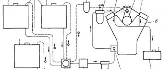
Vehicle fuel system
The fuel system includes the following elements:
- Tank is a sealed container for storing fuel.
- Pipelines (direct and return) – tubes and flexible hoses through which fuel is transported.
- Filters (coarse and fine) – perform cleaning from mechanical contaminants.
- Pressure regulator – necessary to ensure a given pressure level.
- The pump is usually submersible, driven by an electric motor.
- Injection pump – for direct injection systems (diesel engines).
- Fuel injectors.
Fuel filters
Fuel may contain various mechanical impurities and water. Their quantity in gasoline depends on the conditions of transportation, storage and refueling. The presence of mechanical impurities in gasoline is unacceptable, since they
particles contaminate the carburetor jets, which leads to a deterioration in the quality of the prepared combustible mixture, a decrease in engine power and a decrease in efficiency. The accumulation of water in the carburetor float chamber can cause water to flow into the carburetor's mixing chambers instead of gasoline, and the engine will stop (stall).
Fuel filter-sump.
Fuel settling filters are used for rough initial purification of gasoline from mechanical impurities and water.
(Fig. 8, a).
The settling filter consists of a housing in which there is a rod for connecting the housing to the lid 3
using a coupling bolt.
A filter element 5 is placed on the rod and pressed against the cover 3
by a spring.
To drain the sediment, radial and outlet holes are made in the rod, closed by plug 7. The filter element consists of filter plates 9,
closed on top by the element body, and on the bottom by a support washer.
The filter element is assembled onto two stands. The filter plates and the element body have holes that form channels for the passage of filtered fuel 8.
From below, these channels are closed with a support washer.
Rice. 8. Fuel filters;
a – rough cleaning; b and c – fine cleaning
: I, II - body;
2, 4, 10, 12 —
channels; 3 — frames;
5, 13 —
filter elements;
6 -
protrusions;
7 – plug; 8 —
channels;
.9 - filter plates; 14
- settling tank;
15 -
holder;
16 -
wing nut.
The filter plates have protrusions 6,
preventing the plates from tightly adhering to each other.
Fuel enters the filter through hole 4,
to which the fitting of the fuel supply tube from the fuel tank is connected.
The filtered fuel is discharged through hole 2.
The settling filter works Fuel enters the filter under the influence of vacuum created by the fuel pump. If there is water in the fuel, it sinks to the bottom, since it has a higher specific gravity than gasoline. Gasoline passes through the gaps between the filter plates on the outside and inside of the element. Mechanical particles larger than the cracks are retained, and purified gasoline enters the gasoline pump. Drain plug 7 is used to release sludge. The gap between the filter plates is 0.05 mm.
Fine fuel filter
.Small mechanical particles can pass through the filter element of the sediment filter and through the pump inlet strainer. A fine filter is used to clean fuel from the smallest mechanical impurities.
The filter consists of a housing 11
(Fig. 8,
b
and
c
) and a settling cup 14
, connected
and
a wing nut 16.
A gasket is placed between the body and the settling tank to prevent fuel leakage.
The filter element 13
can be made in the form of a glass of porous ceramics. Mesh filter elements are also used, in which a brass mesh is wound around a perforated aluminum glass and secured with a spring. Recently, filter elements made of porous paper have been used.
Car fuel system operation
All the elements considered work in the following sequence... at the moment the engine starts, and on some cars at the moment the driver's door is opened, the fuel pump begins to work, creating the necessary operating pressure in the fuel system necessary to supply fuel to the engine.
As the fuel filter or filter system passes through the engine, the fuel is cleaned of various mechanical impurities. The air enters the combustion chamber or carburetor through an air filter, where it is also cleaned.
Depending on the design of the engine, the fuel-air mixture can be prepared both directly inside the combustion chamber of the engine cylinder, and before entering the cylinder, for example, in a carburetor. A combined method of preparing the fuel-air mixture is also possible.
After the fuel-air mixture is ready and enters the combustion chamber, it ignites. To continue to operate the engine, a constant supply of new portions of fuel is required, for which the fuel system is responsible.
Car device
Carburetor system maintenance
Maintenance and repair of gasoline engine power system devices can be done with your own hands. To do this you need to perform a number of manipulations. They boil down to checking the fastenings of the fuel lines and the tightness of all components. The condition of the exhaust gas system, throttle actuator thrust, and carburetor air damper is also assessed. In addition, it is necessary to monitor the condition of the crankshaft limiter.
If necessary, it is necessary to clean the pipelines and replace seals. A feature of carburetor maintenance is the need to tune it in spring and autumn.
In some cases, the cause of deterioration in the performance of a carburetor engine may be faults in other components. Before starting maintenance of the fuel supply system, you need to check other components of the mechanisms.
Malfunctions in the power supply system of a carburetor-type gasoline engine can be checked with the engine running and turned off.
If the engine is turned off, you can assess the amount of gasoline in the tank, as well as the condition of the rubber seals under the filler cap. The fastening of the gas tank, fuel line and all its elements is also assessed. Other elements of the system should also be checked for fastener strength.
Then you need to start the engine. The absence of leaks at the joints is checked. You should also evaluate the condition of the fine filters and sedimentation tank. The carburetor needs to be adjusted correctly. In accordance with the manufacturer's recommendations, the ratio of air and gasoline is selected.
Functions, structure and principle of operation
Each car is characterized by such a concept as “power reserve”. It is determined by the distance that a car can travel on a full fuel tank without additional refills. This indicator is influenced by a variety of factors: seasonal, weather and natural driving conditions, the nature of the road surface, the degree of vehicle load, the individual characteristics of the driver when driving, etc.). However, the main role in determining the “appetite” of a car is played by the power system and its proper operation.
The power system performs the following functions:
- fuel supply, cleaning and storage;
- air purification;
- preparing a special flammable mixture;
- supplying the mixture to the internal combustion engine cylinders.
The classic car power system consists of the following structural elements:
- a fuel tank designed to store fuel;
- a fuel pump that performs the functions of creating pressure in the system and forcing fuel supply;
- fuel lines - special metal tubes and rubber hoses for transporting fuel from the fuel tank to the internal combustion engine (and excess fuel in the opposite direction);
- fuel purification filter (or filters);
- air filter (to clean the air from impurities);
- devices for preparing the fuel-air mixture.
The power supply system has a fairly simple principle of operation: under the influence of a special fuel pump, fuel from the tank, having previously undergone a cleaning procedure with a fuel filter, is supplied through fuel lines to a device intended for preparing the fuel-air mixture. And only then the mixture is supplied to the engine cylinders.
Petrol
The purpose of the gasoline engine power system is to supply, clean and store gasoline. This is a special type of fuel that has a certain level of volatility and detonation resistance. The performance of the engine largely depends on its quality.
The volatility indicator indicates the ability of gasoline to change its state of aggregation from liquid to vapor. This indicator significantly affects the formation of the fuel mixture and its combustion. During the operation of the internal combustion engine, only the gaseous part of the fuel is involved. If gasoline is in liquid form, it negatively affects the operation of the engine.
Liquid fuel flows down the cylinders. At the same time, oil is washed off from their walls. This situation entails rapid wear of metal surfaces. Also, liquid gasoline prevents the fuel from burning properly. Slow combustion of the mixture leads to a drop in pressure. In this case, the motor will not be able to develop the required power. The toxicity of exhaust gases increases.
Also, another unfavorable phenomenon in the presence of liquid gasoline in the engine is the appearance of soot. This leads to rapid destruction of the motor. To maintain normal volatility levels, you need to purchase fuel in accordance with weather conditions. There is summer and winter gasoline.
When considering the purpose of the gasoline engine power system, one more characteristic of the fuel should be considered. This is detonation resistance. This indicator is assessed using the octane number. To determine the resistance to detonation, new gasoline is compared with the performance of reference types of fuel, the octane number of which is known in advance.
Gasoline contains heptane and isooctane. They are opposite in their characteristics. Isooctane does not have the ability to detonate. Therefore, its octane number is 100 units. Heptane, on the contrary, is a strong detonator. Its octane number is 0 units. If the mixture tested is 92% isooctane and 8% heptane, the octane number is 92.
Power System Options
The main types of fuel for internal combustion engines are gasoline and diesel fuel (“diesel fuel”). Gas (methane) also belongs to the types of modern fuel, but, despite its widespread use, it has not yet become relevant. The type of fuel is one of the criteria for classifying internal combustion engine power systems.
In this regard, power units are distinguished:
- gasoline;
- diesel;
- based on gaseous fuel.
But the most recognized among experts is the typology of engine power systems based on the method of fuel supply and preparation of the fuel-air mixture. Following this classification principle, we distinguish, firstly, the power supply system of a carburetor engine, and secondly, the power supply system with fuel injection (or an injection engine).
Carburetor
The carburetor system is based on the operation of a technically complex device - a carburetor. A carburetor is a device that prepares a mixture of fuel and air in the required proportions. Despite the variety of types, in automotive practice the most widely used is the float suction carburetor, the circuit diagram of which includes:
- float chamber and float;
- atomizer, diffuser and mixing chamber;
- air and throttle valves;
- fuel and air channels with corresponding jets.
The preparation of the fuel-air mixture in the carburetor is carried out according to a passive scheme. The movement of the piston during the intake stroke (first stroke) creates a rarefied space in the cylinder, into which air rushes, passing through the air filter and through the carburetor. It is here that the formation of a combustible mixture occurs: in the mixing chamber, in the diffuser, the fuel escaping from the atomizer is crushed by the air flow and mixed with it. Finally, through the intake manifold and intake valves, the combustible mixture is supplied to a specific engine cylinder, where at the required moment it is ignited by a spark from the spark plug.
Thus, the power system of a carburetor engine is a predominantly mechanical method of preparing the fuel-air mixture.
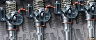
Fuel injection
The era of the carburetor is being replaced by the era of the injection engine, the power system of which is based on fuel injection. Its main elements are: an electric fuel pump (located, as a rule, in the fuel tank), injectors (or nozzle), and an internal combustion engine control unit (the so-called “brains”).
Single injection
The carburetor was replaced by a system of so-called “over-throttle injection” of fuel.
It is also known as single injection or central injection system. The principle is based on fuel injection with a single injector mounted on the engine intake manifold.
The most popular designs of central injection systems are the Mono-Jetronic solutions from RR Bosch and Opel-Multec (as you can guess from the name, this is a solution from Opel Corporation).
The appearance of single injection occurs in the mid-70s of the 20th century. At that time, Volkswagen and Audi cars began to be equipped with the Mono-Jetronic system.
The main task in the development of mono-injection was to find an alternative to the carburetor injection system. It was important to find a more efficient fuel supply system that could meet increased environmental requirements.
Mono-Jetronic: structural elements
- Pressure regulator. It is able to maintain the operating pressure in the injection system at a stable level, and after turning off the internal combustion engine, maintain residual pressure in the system. This is important to facilitate start-up and create barriers against the formation of vapor locks.
- Solenoid valve (injector). Provides pulse fuel injection. The valve is controlled by an electrical signal. It comes from the control unit.
- Throttle valve. Incoming air volume regulator.
- Drive unit. He is responsible for the operation of the throttle valve.
- Electronic control unit. "Brain", synchronizer.
Input sensors (injection timing, throttle position, engine speed, oxygen concentration, etc.).
Distributed injection
In the 70s, distribution injection systems also appeared, based on the supply of fuel by a separate nozzle to the pre-chamber located in front of the intake valve of each engine cylinder. The injection can be either pulsed or continuous.
We will focus on the K-Jetronic solution of the manufacturer Robert R. Bosch with continuous injection. K-Jetronic was actively present on the market from 1973 to 1995. At first, K-Jetronic was produced with a mechanical dosing system. Since 1982 - with electronic filling and electronic dosing control. Starting with versions (modifications) with electronic control, the system began to be called KE-Jetronic.
The economic characteristics of cars, their level of fuel efficiency have been significantly improved, and the level of emissions of harmful substances in the exhaust has also decreased.
In K/KE-Jetronic systems, fuel was injected continuously into the mixing chamber in front of the intake valve. In this case, quantitative dosing of fuel entering the air flow was carried out through interconnected “flow meter – dispenser” units.
In addition to the dispenser-distributor, an obligatory element of the solution is a throttle valve located behind the dispenser. The first versions had vacuum-mechanical fuel correction valves (the valves can be put into operation both from thermostats and from air discharge in the intake manifold), in later modifications electric valves appeared fuel correction. In addition, the systems began to be equipped with an oxygen sensor (lambda probe). A huge advantage of the circuit design was that the injection system could be equipped with a catalyst, but there were significant questions regarding the level of reliability.
Discrete fuel injection
Discrete fuel injection became a new era.
The first here was the L-Jetronic electronic distributed fuel injection system - again from RR Bosch. With the advent of this solution, it became possible to talk about high-quality controllability, reliability, and reliability. Yes, it immediately became clear that this was a medium and high price segment. Therefore, for a long time, discrete fuel injection systems coexisted with continuous distribution injection systems of the K/KE-Jetronic type. But gradually L-Jetronic gained mass popularity. Almost the entire European auto industry began to actively use it. Both drivers and car service personnel appreciated the obvious advantages: the fuel efficiency of the car has increased. Maintenance no longer requires complex skills (primarily, this became possible due to the fact that there was no longer a need to make mechanical adjustments).
L-Jetronic was modernized several times and confidently held its position in the market until the advent of the Euro-3 standard. After which, solutions based on hot-wire mass meter sensors (mass air flow) became more relevant. In particular, the LH-Jetronic modification has gained popularity.
The new development has made it possible to individually adjust the fuel supply to each of the cylinders. The common feature of the Mono-Jetronic, L-Jetronic, LH-Jetronic systems is that all these solutions control only fuel injection, while the ignition system with a module is used to ignite the fuel electronic control.
RR Bosch Corporation began producing devices in which the ignition and injection systems were synchronized and combined in 1979.
A striking example of a solution with integrated injection and ignition systems is the Motronic system from RR Bosch. It existed in several modifications that appeared in the 90s of the 20th century. During these years, their designs included mechanical air flow meters. But soon hot-wire flow sensors began to be used instead of them, and the possibilities for self-diagnosis expanded.
True, the systems could not fully satisfy the diagnostician’s needs, since the fault detection protocol was not highly effective. In subsequent modifications this problem was successfully solved.
But the most revolutionary solution of Motronic was the appearance of the absolute pressure sensor in the intake manifold (MAP-sensor).
The use of a MAP sensor in the engine control system made it possible to prepare a high-quality air-fuel mixture, the composition of which is close to the desired one, and, most importantly, it is not difficult to comply with European requirements for vehicle emissions.
But even this was not enough to enter the American market. According to US standards, the fuel system must have a mandatory system for monitoring fuel vapor leaks from the tank. This is how the innovative Motronic M5 solution was born. With it, all the conditions appeared to prevent the operation of a car with a leaky filler cap or a faulty fuel tank ventilation system.
In addition, this system meets the strictest OBD-II/CARB self-test protocol.
And thanks to the electric throttle control, the interaction between the engine management system and the braking system is streamlined.
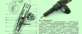
Direct injection systems Direct injection systems have received a special place among the injection systems of gasoline engines. Their operating principle is based on the fact that fuel is sprayed directly into the engine cylinder through an injector.
- This is important for achieving fuel efficiency.
- Plunger pump. It supplies fuel to a ramp connected to the injectors.
- Fuel pressure control. Maintains stable operating pressure in the fuel rail. Fuel rail. Here the process of distributing fuel to the injectors directly occurs.
- Safety valve on the ramp. Protects the ramp from extreme pressures.
- High pressure sensor. It measures the pressure in the rail and sends a signal to the engine control unit to correct the pressure.
Coordination of the interaction of nodes is carried out through an electronic engine control system. Commands are sent to the actuators from the electronic control unit.
Interesting detail!
While such fuel systems have been popular among diesel injection systems for a long time, they did not immediately become widespread among gasoline injection systems. The reason is quite simple: gasoline, unlike diesel fuel, is a poor lubricant, which caused rapid wear of the fuel pump.
But with the development of sealing technology, developers were again able to work on gasoline direct injection systems. The direct injection system can provide several types of mixture formation: layer-by-layer, uniform (homogeneous), and stoichiometric. Layer-by-layer mixture formation is relevant at low and medium speeds, stoichiometric and homogeneous - at ultra-high speeds, as well as at medium and high loads.
The most popular solutions are with layer-by-layer mixture formation. They are well known by the names FSI and TFSI (Volkswagen and Audi). The letter “T” in the name indicates the presence of a turbocharger, that is, the engine is colloquially referred to as “turbocharged”.
A small amount of fuel enters the cylinder of such gasoline injection systems. Careful organization of the air flow in the cylinder (its trajectory of movement is similar to a “somersault”) and well-chosen timing of fuel injection into the cylinder create all the conditions for this small amount of fuel to be supplied to the electrodes of the spark plug, and ignition of this portion of the combustible mixture occurs.
Why isn’t everyone switching to this gasoline injection system? Unfortunately, such a problem as “turbo lags” occurs when you sharply press the gas pedal.
This drawback is completely eliminated with the presence of an electrically driven supercharging unit. Such systems are not cheap. But quickly reaching maximum power mode and avoiding “turbo burns” when you sharply press the gas pedal with them is not a problem. Direct injection SC-E is relevant, for example, for a number of sports cars.
There is also very high interest in bi-fuel (binary) systems with gas turbine supercharging. When running on gasoline, very good torque can be achieved.
The parameters of the fuel used are recorded in permanent memory. If it is necessary to replace gasoline with an alternative fuel, the mixture formation program is changed. It is very comfortable.
Malfunctions and service
During the operation of the vehicle, the vehicle's fuel system experiences loads that lead to its unstable operation or failure. The following faults are considered the most common.
Insufficient supply (or lack of supply) of fuel to the engine cylinders
Poor quality fuel, long service life, and environmental exposure lead to contamination and clogging of fuel lines, tank, filters (air and fuel) and technological openings of the combustible mixture preparation device, as well as breakdown of the fuel pump. The system will require repairs, which will consist of timely replacement of filter elements, periodic (every two to three years) cleaning of the fuel tank, carburetor or injector nozzles and replacement or repair of the pump.
Engine power loss
A malfunction of the fuel system in this case is determined by a violation of the regulation of the quality and quantity of the combustible mixture entering the cylinders. Troubleshooting involves the need to diagnose the combustible mixture preparation device.
Fuel leak
A fuel leak is a very dangerous phenomenon and is absolutely unacceptable. This malfunction is included in the “List of malfunctions...” with which the vehicle is prohibited from moving. The causes of the problems lie in the loss of tightness of the components and assemblies of the fuel system. Troubleshooting involves either replacing damaged system elements or tightening the fuel line fastenings.
Thus, the power system is an important element of the internal combustion engine of a modern car and is responsible for the timely and uninterrupted supply of fuel to the power unit.
I like3I don't like
What else is worth reading
VAZ 2109 generator device
The design of the chassis of the VAZ 2109
Intake manifold device
Fuel pump
Fuel pump
A fuel pump is used to force fuel to the carburetor. On ZIL-431410 car engines, the fuel pump is driven by the camshaft eccentric through a rod; on carburetor engines of GAZ-3110 Volga, GAZ-3307 and IZH-2126 Oda cars - directly from the camshaft, on VAZ engines - by the eccentric shaft drive of the lubrication pump and ignition distributor. Diaphragm pumps are the most widely used
characterized by good performance.
Pump B-10 of carburetor engines of ZIL cars (Fig. 5, a)
consists of three main parts: body
2,
valve head 7 and cover
10.
The pump body contains a rocker arm 17, a discharge spring
4
, a roller
14
a lever
1
of the manual fuel pumping mechanism.
The valve head 7 has three outlet valves 13
and three inlet valves
8,
above which there is a strainer
9.
The cover
10
has a partition
11
separating the inlet A and discharge B cavities of the pump.
Between the valve head 7 and the body 2
is clamped a multilayer varnished fabric membrane
6,
mounted on a rod
5,
the lower end of which is connected through a washer to the inner fork arm of the rocker arm 17, and its outer arm is constantly pressed by a spring 15 against the rod
18
of the pump drive.
Power system operating modes
Depending on the goals and road conditions, the driver can use different driving modes. They also correspond to certain operating modes of the power supply system, each of which has a special quality fuel-air mixture.
- The mixture will be rich when starting a cold engine. At the same time, air consumption is minimal. In this mode, the possibility of movement is categorically excluded. Otherwise, this will lead to increased fuel consumption and wear of power unit parts.
- The composition of the mixture will be enriched when using the “idling” mode, which is used when coasting or running the engine in a warm state.
- The mixture will be leaner when driving with partial loads (for example, on a flat road at medium speed in high gear).
- The mixture composition will be enriched at full load when the vehicle is moving at high speed.
- The mixture will be rich, close to rich, when driving under conditions of sharp acceleration (for example, when overtaking).
The choice of operating conditions for the power system, therefore, must be justified by the need to move in a certain mode.
Which injection is better?
People often argue about which injection is better.
The cheapest solutions are those focused on distributed injection. It is also captivating that they are not picky about the quality of fuel. If it is important for you to have high fuel efficiency with minimal emissions, you should definitely choose direct injection. Yes, these solutions are more expensive. But it’s better to pay more once than to constantly “eat up” excess fuel.
By the way, the high cost of the solution is mainly due to the fact that manufacturers had to make fundamental changes to the design of the cylinder heads; however, these engines are much more expensive to repair than simple and reliable engines with distributed pre-chamber fuel injection.
A specialized simulator on the ELECTUDE platform will help you not only study fuel systems, but also practice working in finding various faults in them. An excellent help for automotive mechanics and diagnosticians.
Scheme, device and principle of operation for a diesel engine
Common rail fuel system diagram
Diesel fuel supply systems have their own characteristics. There are three types of structures:
- Common rail (or battery);
- With pump injectors;
- Separated.
Common rail
The most popular fuel system for diesel engines is battery (or common rail) . It meets higher environmental standards. This is ensured due to the independence of diesel injection processes from engine operating modes.
Structurally, the common rail diesel power system has two main circuits:
- Low pressure section - consists of a fuel tank, low pressure pump, pipelines and filter.
- High pressure section - consists of a high pressure fuel pump (HPF), a pipeline, a ramp (accumulator) and injectors.
The operating principle of the diesel fuel system is the following sequence:
- The low pressure pump forces diesel from the fuel tank into the pipeline.
- Passing through the pipeline through coarse and fine filters, diesel is supplied to the high pressure pump.
- The fuel injection pump supplies fuel to the injectors, which are used to inject fuel into the cylinders.
- Air is supplied simultaneously with fuel injection.
Split and unit injector
Pump-injector
The divided fuel system consists of a fuel tank, pipelines, injection pump and injectors. In this case, the pump and nozzles are connected by long pipelines designed for high pressure. The divided circuit is actively used in the domestic automotive industry, since it is characterized by low cost and simplicity of design .
In turn, a pump injector is a device that simultaneously creates the required level of pressure and injects fuel. It is located in the cylinder head and is driven by a cam mechanism. The forward and return lines are implemented as channels located directly in the block head.
The operating pressure with this scheme is up to 2,200 bar.
This method has an important drawback - it is characterized by the dependence of pressure on the engine operating mode.
Injector
The injection engine is a modern internal combustion engine design. It significantly exceeds carburetor power systems for gasoline engines in all respects. An injector is a device that provides fuel injection into the engine. This design allows for high engine power. At the same time, the toxicity of exhaust gases is significantly reduced.
Injection engines are characterized by stable operation. The car demonstrates improved dynamics when accelerating. In this case, the amount of gasoline that the vehicle requires to move will be significantly lower than that of a carburetor power system.
Fuel with an injection system burns more efficiently and completely. At the same time, the process control system is fully automated. There is no need to manually configure the unit. The injector and carburetor differ significantly in design and operating principle.
The fuel injection system for a gasoline engine includes special injectors. They inject gasoline under pressure. It is then mixed with air. This system allows you to save fuel consumption and increase engine power. It increases to 15% when compared with carburetor types of internal combustion engines.
The injection engine pump is not mechanical, as was the case in carburetor designs, but electric. It provides the required pressure when injecting gasoline. In this case, the system supplies fuel to the desired cylinder at a certain time. The entire process is controlled by an on-board computer. Using sensors, it evaluates the amount and temperature of air, engine and other indicators. After analyzing the collected information, the computer makes a decision on fuel injection.
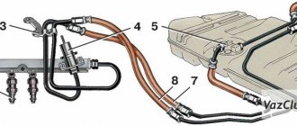
Fuel return line (“return”)
Fuel systems
As a rule, the fuel pump has a constant capacity, that is, it pumps fuel from the tank into the ramp under constant pressure . The engine operates in different modes, consuming different amounts of fuel, depending on its load. Thus, it becomes necessary to control the pressure and amount of fuel in the fuel rail.
This is done by the fuel pressure regulator, which drains excess fuel back into the tank through the fuel return line , the so-called “return”. Currently, there are two types of fuel systems, differing in the presence or absence of a fuel return line (return line).
- Fuel supply system with return line . Fuel that is not injected by the injector is excess fuel and it returns back to the tank through the regulator, which is located on the fuel rail, and the return line. In this way, constant pressure is maintained in the fuel manifold.
- Fuel system without return line . The fuel pressure regulator in such systems is usually installed in the submersible fuel pump module. Excess fuel supplied by the pump is returned back to the tank through a short return line. In this case, only the amount of fuel that is injected by the injectors is supplied to the fuel rail. This system has the following advantages: lower cost and less heating of the fuel in the tank.
Sources
- https://autodromo.ru/articles/toplivnaya-sistema-avtomobilya-sistema-podachi-topliva-ustroystvo-naznachenie-princip
- https://ZnanieAvto.ru/toplivo/sistema-pitaniya-dvigatelya-avtomobilya.html
- https://topdetal.ru/stati/kakie_byvayut_vidy_sistem_pitaniya_dvigatelya/
- https://TechAutoPort.ru/dvigatel/toplivnaya-sistema/toplivnye-sistemy-benzinovyh-i-dizelnyh-dvigateley.html
[collapse]
Device evolution
The number of cars is growing every year, emissions into the atmosphere are becoming more and more. Therefore, engineers of large concerns are fighting for the ecology of emissions, systems such as EURO are being adopted, now in Russia they have already reached “EURO 5”, in Europe this is already “EURO 6”, and “EURO 7” should appear soon. Each increasing level imposes strict requirements on many components, and in particular on the fuel supply system; if such requirements did not exist, it is quite possible that we would still be riding on “carburetors”, or let’s say on “mono-injection”. In the design of our cars, there would be no such parts as a catalyst. But ecology is ecology, and in general I support manufacturers; to be honest, I’m generally in favor of electric cars or, for now, hybrids. Still, living on a dirty planet is not entirely good! Well, okay, this is a lyrical digression - but now to the point.
If you track the evolution of fuel supply systems, and today I’m talking specifically about gasoline options (we’ll talk about diesel later). Then we can define only five main structures, in increasing order. SO:
- Carburetor
- Mono injection (or central)
- Distributed injection
- Direct injection
- Combined system
As you understand, the very first was the carburetor (very environmentally friendly, EURO1 standard), now the most progressive type is direct injection (the most environmentally friendly at the moment, EURO5 - EURO6). Let's take a closer look at each design; many are probably waiting.