01 December 2016 Lada.Online 90 478 7
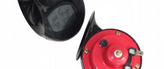
All cars have a device for producing sound signals (horn), but its sound does not always suit the owner. This is the main reason for replacing the standard horn with alternative options (for example, with a sound signal from the Volga). Let's look at this improvement in detail.
Nowadays, horns are usually used in pairs. One with a high tone, the other with a low tone. This provides strength and beauty of sound.
Will need to buy:
- A couple of sound signals from GAZ 3110 (article number for high tone - 22.3721, for low tone - 221.3721), or an analogue, approximate price 500 rubles; Other sounds in this category.
- 4-pin relay 75.3777-10;
- Relay socket;
- Mounted fuse 10-15A;
- Single-core wire;
- Corrugation for wires;
- Terminals;
- Brackets/brackets for mounting sound signals (optional).
Installation and connection of a sound signal from the Volga is shown using the example of the Lada Vesta sedan. On other cars (for example, Lada Largus, Granta, Kalina, Priora, Niva 2121 or XRAY) all actions are performed in a similar way.
How to install a Volga signal
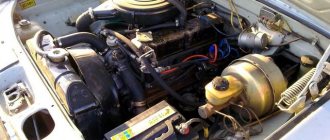
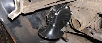
Remove the front bumper (instructions for XRAY, Vesta, Grant, Priora, Kalina, Largus). If it was decided not to remove the standard sound signal (if necessary, you can return to the initial version), then we are looking for a suitable place to install signals from the Volga. Most often they are placed on the front bumper amplifier (on standard mounting bolts), behind the radiator grille or under the headlights on brackets.
FakeHeader
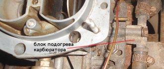
That's it, the mechanical part is over, let's move on to the electrical part. As a rule, the horn device is located behind the engine radiator grille, directly in front of the main radiator device. As practice shows, often the cause of failure lies in their oxidation, so it makes sense to clean the contacts. Already crimped wires with terminals are sold in stores.
That's it, the mechanical part is over, let's move on to the electrical part. (easy and fast) Volgov Signals on VAZ 2107
How to connect the Volga signal
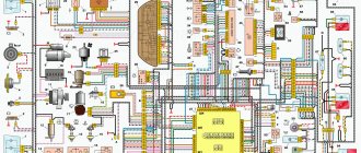
Standard sound signals of LADA cars consume no more than 5A, and Volga horns consume 7A each. In this regard, to connect them it is necessary to use a 4-pin relay. The owners claim that it is not necessary to install an additional relay. The Volga signal connection diagram is universal for all cars:
Before starting work, it is recommended to disconnect the negative terminal from the battery. All wires are laid in corrugation. We place the relay in a place protected from moisture and dirt. The whole process is also shown in the video:
About the guarantee. If you independently modify the car in terms of electrical components, there is a possibility of refusing warranty service for the car. Therefore, the installation of signals from Volga should be carried out at a service center, where after connection they will be ready to provide a document confirming the quality of work. You can also contact an authorized dealer for such modifications.
Are you satisfied with the operation of the standard sound signal on the LADA model? Are you ready to install a Volga horn?
By the way, on Lada Vesta and Xray you can install louder FIAMM sound signals without interfering with the wiring.
Keywords: lada xray safety | safety of Lada Vesta | safety of Lada Largus | safety of Lada Granta | safety of Lada Kalina | safety of Lada Priora | 4x4 safety | Niva safety | universal article
0 0 0 0 0 1
Share on social networks:
Signal connection diagram via 4-pin relay
In my opinion, everything is already clear, and they have already written about this many times, but it may be useful to someone. For example, I recently gave a car I had made to a man, and over time his signal stopped working. You can’t travel all over Moscow for trifles, so he asked me to draw a diagram for him, I did it, but don’t disappear. I decided to post it publicly.
Description, I will try to use simple understandable language:
Two opposite contacts on the relay, numbered No. 86 and 85, are the so-called control contacts. If voltage is applied to them, the relay will close, and then direct voltage will flow through contacts No. 30-No. 87. Well, let’s say a contact that you need to break and briefly close, let’s say a signal. Why through a relay? Well, let’s take the interior button for example, the contacts on the buttons are weak and are not designed for direct load, and if you apply the plus from the battery through the button, say, to the starter, then after the first use the button will melt. Therefore, through the interior button we connect the control wires to the relay, and the direct plus to the consumer, in our case the signal. Thus, through a relay from the battery to the input (contact No. 87) and output (contact No. 30) to the consumer (Signal).
What is a control minus? Usually, on the relay, the minus goes directly to contact No. 86, and the control plus is opened with a key (button). In our case, the key (button) already exists, this is the signal button on the steering wheel. The way it is designed, the steering shaft is connected to the steering column and body through rolling bearings, and there is always a constant minus on it. Next, the minus from the steering shaft is fed to the core of the steering wheel, a contactor is installed in the steering wheel itself, to which the minus from the steering wheel fits on one side, and on the other side the contact goes to a contact round plate (most often copper or brass) along which on the steering side the stationary contact slides on the shaft, it then removes the minus from the steering wheel button and sends it further to the signal, in our case to the relay, to contact No. 86. So, not everything is so complicated and shrouded in mystery; if you have never dealt with electrics, then don’t go into details, just connect according to the diagram, which in my opinion is quite simple. I hope my article will help someone.
It is often difficult for novice auto electricians and people modifying their car to understand the phrase “connect via a relay.” What does connecting via a relay mean and how to do it? Let's figure it out.
Before studying the wiring diagram for any automotive device via a relay, you need to know what a relay is in general and how it works. This is written about in detail here
. Once you understand the operating principle of this simple device, it will be much easier to figure out how to connect it.
The general meaning of connecting via a relay is the load on the switch that controls the installed equipment. All powerful consumers of electricity in the car (for example, headlights, starter, fuel pump, heated rear window, electric power steering) are connected through a relay. Thanks to this, these devices can be controlled by small, beautiful buttons instead of rough and large switches. In addition, in some cases, the relay allows you to save on wires.
The relay is connected to an open circuit in the electrical circuit. Let's look at installing a relay using the example of a gas pump. Power is supplied to it by the engine control unit (hereinafter referred to as the computer) and in order for the computer board tracks to withstand the current consumed by the pump, they would have to be made too powerful. Passing strong current near sensitive electronic components of a computer can affect their operation. To avoid such problems, a relay is installed between the computer and the fuel pump and the computer is connected not to the pump, but to this little “helper”.
The relay, as it were, divides the wire going from the fuse block to the pump into two parts, which can close inside the relay when voltage is applied to the control contacts of the magnet. As already mentioned in the article about the relay device, the control current is very small and cannot damage the computer in any way. The computer supplies voltage to the control contacts of the relay, and it then “connects” the power circuit within itself and connects the fuel pump.
Using the same principle, the relay is installed on any other electrical consumers in the car. Let's consider connecting fog lights.
The wires to the fog lights come from the fuse box, but they go through a relay along the way. The process of turning the headlights on/off is controlled by a button on the dashboard. When it is pressed, voltage is supplied to one of the control contacts of the relay, and it closes the power circuit - the lamps in the headlights light up. The second control contact of the relay is “mass”, that is, voltage goes through it to the car body, creating an electrical circuit.
Using this circuit, you can connect almost any powerful device and control it with a small, beautiful key. In some cases, a relay can be a salvation from factory defects. For example, in a VAZ-2106, the current flowing to the starter solenoid relay through the ignition switch quickly leads to a malfunction of the lock contact group
. They get rid of this trouble by installing an intermediate relay and changing the power supply of the solenoid relay. After modification, a weak control current begins to pass through the contact group of the lock, and the relay connects powerful power to the starter.
Sound signal GAZ in NIVU
Lately there have been a lot of inappropriate behavior on the roads. Few people pay attention to the native quiet signal. Therefore, I decided to install a signal from GAZ. I bought the following signals produced by LETZ without brackets:
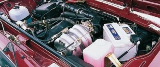
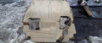
I decided to put it behind the radiator grille, because... Under the hood the sound would still be a little muffled. Standard signal:
To place the signals, I made the following mounts from stainless steel:
Connection diagram via relay:
True, I took the power from fuse No. 15 which is 16A
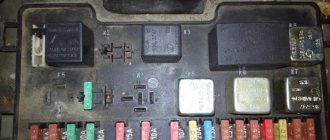
Blocks in the cabin
Fuse box
Option 1
It is located in the cabin, above the glove compartment and consists of two parts. To access, you need to slide the protective strip.
Photo - diagram
Description
Left block
| 1 | 25A Heater (air conditioning) electric motor |
| 2 | 15A High beam right headlight |
| 3 | 15A Main beam of the left headlight, high beam headlight indicator |
| 4 | 10A Low beam right headlight |
| 5 | 10A Low beam left headlight |
| 6 | 10A Rear fog light |
| 7 | 20A 2008 Radio equipment 2005 Injection system devices |
| 8 | 20A Cigarette lighter , horn relay, horns |
| 9 | 15A 2008 (Euro-3): Engine management system 2008 (Euro-2): Electric fuel pump, oxygen sensor 2005: Heated mirrors, electric fan relay coil |
| 10 | 10A 2008 (Euro-3): Electric fuel pump 2008 (Euro-2): Engine management system 2005: Radio equipment |
| 11 | 5A 2008 (Euro-3): Engine control unit 2008 (Euro-2): Turn signals, relays and turn signal indicators 2005: Electric drives of exterior mirrors, forced idle economizer unit (ZMZ-402), oxygen sensor (3M3-40621) |
| 12 | 15A Engine compartment lamp, glove box lamp, interior lamp |
| 13 | 10A 2008 (Euro-3): Turn signals, relays and turn signal indicators 2008 (Euro-2): Engine control unit, ignition coils 2005: Windshield wiper, headlight washer relay |
Fuse number 8 at 20A is responsible for the cigarette lighter.
| 1 | 25A Fog lights |
| 2 | 15A Heater (air conditioning) control unit, rear window heating relay, rear window heating (1 mode), additional heater |
| 3 | 15A Speedometer sensor, instruments, warning lights, reverse light, electric fan relay |
| 4 | 10A Brake lights |
| 5 | 10A Hazard Alarm |
| 6 | 10A Left side lights, fog light relay, side light indicator |
| 7 | 20A Heated rear window (mode 2), interior lamps, rear door, rotating headlight (medical car) |
| 8 | 20A Glass lifts |
| 9 | 15A 2008: Windshield wiper, headlight washer relay 2005: Ignition coils |
| 10 | 10A Anti-lock Brake System ABS |
| 11 | 5A 2008: Power and heated exterior mirrors 2005: Turn signals, relays and turn signal indicators |
| 12 | 15A Locking |
| 13 | 10A Right side lights, electric headlight range control, lighting: trunk, license plate, instruments, cigarette lighter, switches, medical sign lights, taxi |
Option 2
Located in the cabin under the instrument panel, on the driver's side behind the protective cover.
Scheme
Designation
Upper block
| 1 | 25A Heater (air conditioning) electric motor |
| 2 | 15A High beam right headlight |
| 3 | 15A Main beam of the left headlight, high beam headlight indicator |
| 4 | 10A Low beam right headlight |
| 5 | 10A Low beam left headlight, low beam headlight warning light |
| 6 | 10A Rear fog light |
| 7 | 20A Radio equipment |
| 8 | 20A Cigarette lighter , horn relay, horns, instrument cluster, clock |
| 9 | 15A Euro-3 Engine management system, Euro-2 diagnostic connector: Electric fuel pump, oxygen sensor (ZMZ-40621) |
| 10 | 10A Euro-3 : Electric fuel pump Euro-2: Engine management system, diagnostic connector |
| 11 | 5A Euro-3: Engine control unit Euro-2: Turn signals, relays and turn signal indicators |
| 12 | 15A Engine compartment lamp, glove box lamp, interior lamp |
| 13 | 10A Engine control unit, ignition coils (ZMZ-40621) |
Fuse number 8 at 20A is responsible for the operation of the cigarette lighter.
| 1 | 25A Fog lights |
| 2 | 15A Heater (air conditioning) control unit, heater valve, front lamp, interior temperature sensor, fog lamp relay coil, + (ZMZ-40525, Chrysler 2.4L-DOHC (Euro-3): speedometer sensor, reverse light, instrument cluster ) |
| 3 | 15A Euro-3: Hazard alarm Euro-2: Speedometer sensor, reverse light, instrument cluster |
| 4 | 10A Brake lights |
| 5 | 10A Euro-3: Direction indicators, relays and indicators Euro-2: Hazard warning lights |
| 6 | 10A Left side lights, side light indicator |
| 7 | 20A Heated rear window and heated exterior mirrors |
| 8 | 20A Window lifters |
| 9 | 15A Windshield wiper and washer |
| 10 | 10A Anti-lock Brake System ABS |
| 11 | 5A Electric drive of exterior mirrors |
| 12 | 15A Locking |
| 13 | 10A Right side lights, electric headlight range control, headlight washer relay, trunk light, license plate light, instrument light, cigarette lighter light, switch light, medical sign light, taxi |
Relay block
It is attached near the left drain, under the driver's side panel, behind the trim.
Scheme with decoding
- Warning lamp relay
- Starter relay
- Fog light relay
- Signal relay
- Heated rear window relay
- High beam relay
- Low beam relay
- Rear fog lamp relay
- Wiper relay
- Engine cooling fan relay
Separately, outside the block, on the turn signal switch itself, there is a turn signal relay.
see also
Comments 55
You can connect and since you wrote only then the signal will work even without turning the ignition to the ACC position
Somehow the circuit is not logical because 85 and 86 contacts should be control contacts, that is, for low current control, and 30 and 86 for high current, that is, for load control
I installed the air one. The original fuse blew, I installed a stronger one and everything works. I didn’t install any additional relay, because... the original relay from the factory is
Will the wiring hold up?
I think yes. I signal no more than a couple of seconds, it won’t even have time to warm up
It is possible if the control of the standard signal is negative.
Either as sanya05 corrected, or if the plus is controlled, then you can connect 85 and 87.
I installed powerful signals, but they are controlled by a plus and the original ones by a minus, I connected them through a relay to a friend, but now both the factory ones and the ones I installed work
I didn’t want to say anything, but after reading the recommendations, which did not answer the question, I decided to answer. The question sounded like this: “But a question arose. Why can’t you connect + from the battery that goes to terminal 30 of the relay to the standard socket, that is, put a jumper between 30 and 86.” It is possible, but if we want a good signal, then it is necessary to connect a wire of the appropriate cross-section to it so that there is no interference with the flow of electrons, and an operational circuit is usually connected to pin 86, i.e. a thin wire, which will create a delay in the movement of electrons and, as a result, heating of the wire, and the signal will sound quieter, and most importantly, the contact ring in the steering column mechanism is unloaded with the help of a relay and lasts a long time. I didn’t explain it clearly, I wouldn’t make a teacher. Connect according to your diagram and you will be happy, the diagram is correct. Oh, and you may already have a relay from the factory. You can easily check. Disconnect the terminal from the signal and with the ignition on, press the signal; if you hear clicks (listen well), then your relay is not needed at all.
I also have a relay from the factory, but since I installed the air vent, I connected it according to the diagram from above, because the air takes a lot, and the original one just burned out, and with it, Carlson didn’t turn on
The fuse is not an indicator, it can be installed in any way, the point is in the cross-section of the wire (the number of electrons per unit time that can “slip” in this cross-section) which can “switch” the relay.
Yes, you can burn the track in the mounting block, because... if Carlson works and forces you to press it, it could end badly, that’s why I powered it from the battery with a normal wire
The fact that you powered the signal with a normal wire is no worse, I’m talking about something else, that the standard relay can be powered with exactly the same - a normal wire, and then there is simply no need for an additional relay, although, if you wish, you can install another a dozen relays - it definitely won’t get any worse.
There is a thin wire there, it goes to the standard signal, it now turns on the relay
If it’s thin, then there was no relay there, you don’t need to call grandma, then everything is correct.
Well, why didn’t it happen right away? Just enough for a standard signal
Because there is no point in spending money (for the manufacturer) on a relay if the signal power does not exceed the power of the circuits.
Dial mounting block 2114 and see the horn relay
No time, I give up! I don't understand this charm if it's true.
the whole joke is because of the control, the 2112 has a constant plus, but the steering wheel closes to ground, there is no relay, the 2114 has a negative control, but the plus opens on the signal, I don’t know why it’s done that way
86+30, and short the horn to ground. In a word, make control by minus and relieve the horn contacts and remove the excess wire. The signal should work without turning on the ignition - this is the first thing. If a constant + comes to the tip of the relay, then this does not mean anything until a control signal appears - that’s two. On a good note, any modern car should have a native relay for turning on the signal. If this relay is not in the car, then additional re-equipment is carried out due to an increase in the current consumption of the new signal or if it is impossible to restore the factory horn activation circuit.
I haven’t read all the posts - maybe I’ll repeat myself. There is a small (major) flaw in the whole scheme. The relay is installed to relieve the control contact - in this case, the horn button. The button turns on the relay, and it, in turn (with independent contacts), turns on the horn. And you?! Along with the signal, there is also a relay attached to the standard button! Where is the contact relief?! In this design (connection), the relay performs the function of a “clicking element” - nothing more. You need to disconnect the “30” contact from “86” and connect it to the + battery.
Realized the mistake. Thank you.
The second scheme is fundamentally wrong. They don't do that. The relay is pointless here! If the signals are controlled by positive, do not install a jumper. If on the negative side, you can safely install the jumper and power everything from the battery
Why is a relay installed? That's right, to relieve the load on the car wiring that comes from the steering wheel. The steering unit, slip ring or cable cannot withstand heavy loads. If you install powerful signals, then the power should come from the battery through the pre and relay, but the relay is controlled from the button on the steering wheel. The control polarity depends on the car. If there is a “minus” signal from the button, then you can safely power contacts 30 and 86 together from the battery, but not forgetting that the wires on contacts 30 and 87 must have the appropriate cross-section to power the signals, and you can even hook “noodles” to control the relay. In the last diagram there is no point in using a relay because it does not relieve the wiring from the button.
The fact that you will have constant power on the wire from the battery to the relay is nothing to worry about. When you take the key out of the lock, you are left with a lot of wires that provide power to the relay. If this is important to you, then you can install another relay at the battery that will turn on the power when you turn on the ignition, or install a signal control relay next to the battery and the power wire will be as short as possible.
Everything arrived. Thank you.
relays are installed if the signals consume more current, then your circuit will kill the very idea, but if the signals are connected in a native way, with a button to ground, then it will beep incessantly
In short, it doesn't matter. Whatever your heart desires, as long as there is a fuse and wires of the appropriate cross-section.
Possible malfunctions: signs and causes
By what signs can you determine that a car horn needs repair:
- The steering horn does not work. When the driver presses the steering wheel button, the sound device does not work.
- The device sometimes works, sometimes it doesn’t. When you press the button on the steering wheel, the horn first sounds and then disappears.
As for the reasons why a device may fail, there are many:
- A fuse located in the fuse block under the hood or inside the vehicle has blown. In case of such a problem, the operation of the horn can be restored, since it is not damaged. The car may also, in addition to the fuse, have a relay.
- The horn itself is broken. If you replaced the safety element, but this did not help solve the problem, then you need to check the horn itself. To do this, the device will need to be removed, and its contacts will need to be connected directly to the battery. When connected directly, a functional horn will sound.
- In some cases, the reason lies in the appearance of a short circuit in the vehicle's electrical network. A short may affect the connection circuit, so you must first check the functionality of the fuse socket. Sometimes the horn may not work correctly due to circuit damage and current leakage.
- Also, the cause of the malfunction sometimes lies in worn-out clamping contacts located on the steering column. A malfunction of this type is more typical for domestic cars. As a result of long-term use, the springs begin to wear out over time, which leads to the fact that the impulse through them cannot be transmitted from the button to the buzzer itself.
- It also happens that the slip ring wears out right on the steering wheel.
- If the contacts are not worn out, then they could simply oxidize. Long-term use, as well as lack of maintenance, lead to deposits forming on the contacts over time. As mentioned above, this problem can cause difficulty transmitting the signal to activate the buzzer.
- The contact blades are located under the steering wheel hub. This petal may burst over time; sometimes the cause should be sought in the jamming of the pressure rack.
- The horn winding is burnt out.
- Sometimes the horn malfunction is due to a damaged electrical connection or an accidental disconnection of the terminal directly on the signal itself.
- Sometimes the reason for a non-working signal may be a break in the cable on the steering wheel on cars equipped with an airbag (video published by the channel Learning to drive a car. All secrets for beginners).