Even with a perfectly adjusted high and low beam light beam, you often have to adjust the angle of the headlight reflector. This is primarily due to the loading of the car. If, according to the rules for adjusting the headlights of the VAZ-2110, we start from the load of the driver + front passenger, then in real life, when the cabin is fully loaded, our adjustment will leave no stone unturned. The rear of the car will squat, the front will rise and the light beam will blind oncoming drivers. To quickly adjust the angle of the headlight reflector, a hydraulic corrector is installed in all VAZ-2110s.
The principle of operation of the VAZ-2110 headlight hydraulic corrector
Its purpose is clear - without leaving the cabin, the driver can change the angle of the light beam relative to the road. The device must work correctly with two headlights at once and have a sufficient range of adjustment - to maximize the angle of the reflector when the rear part of the body is fully loaded, and also reduce the adjustment to zero when the load is minimal.
The principle of operation of the headlight hydrocorrector.
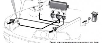
The VAZ-2110 hydraulic corrector, installed as standard, consists of:
- main hydraulic cylinder and switch, both of them are assembled in a single block and installed to the left of the steering wheel on the front panel;
- hydraulic drive system, line - tubes that connect the elements of the system;
- working hydraulic cylinders, actuators that raise or lower the headlight reflector;
- working non-freezing liquid.
The low-pressure hydraulic system allows you to change the working pressure and move the rod of the working cylinders within 6–7.5 mm . In theory, this is enough to change the angle of installation of the reflector from minimum to maximum and, accordingly, change the direction of the angle of the light beam.
How to make automatic headlight leveling with your own hands
If it is almost impossible to make a dynamic auto-corrector with your own hands, then an electromechanical corrector (EMKF) can be made independently. Such a device can replace the hydraulic corrector on all models of domestic cars for which this is provided for by the design of the head optics.
The typical design of an electromechanical corrector consists of gear motors installed on each headlight and a control unit. The corresponding components can be purchased freely. Plus you will need a soldering iron, wires, fasteners, terminals, pads, casing, PVC tube or other insulating material.
It is necessary to select components for the EMKF in such a way that their dimensions correspond to the dimensions of the standard hydraulic corrector installed on your car.
Malfunctions and diagnostics of hydraulic corrector
Despite the simplest design, the hydraulic corrector is considered one of the most unreliable systems in cars of the tenth family. Design flaws, quality of materials and workmanship force us to return to the problem of adjusting headlights almost every year.
In this case, neither the working nor the main cylinders can be repaired and require replacement if they fail.
The signs of a malfunction are clear - the headlights do not respond to the corrector knob and are frozen in one position . The most common problem is depressurization of the hydraulic system. This trouble can be easily calculated by the leakage of liquid from the system, and it is also easy to eliminate. It is enough to seal the joints (on the cylinders) of the hydraulic system and check its operation again.
Another problem is fluid leakage through the cuffs of the working cylinders . No one is going to repair cheap plastic cylinders; they are replaced with new ones. By the way, the price of a new hydraulic corrector for the VAZ-2110 and all cars of the family (article 2110–3718010 and 2110-3718010-10 ) is 450–550 rubles, depending on the manufacturer. The difference between them is the stroke of the working cylinder rod. For tens in a station wagon, a larger load and a larger adjustment angle are provided. Accordingly, a larger stroke of the cylinder rod.
You can check the operation of the headlight hydraulic adjustment system by measuring the working stroke of each of the working cylinder rods:
- 2110–3718010 — working stroke 6–7.5 mm for sedan and hatch;
- 2110-3718010-10 — working stroke 6–8.5 mm for a station wagon.
If the hydraulic cylinders do not work or the working stroke does not correspond to the nominal values, we replace them and install a previously purchased new hydraulic corrector of the appropriate modification.
Purpose and tasks
Actually, even from the name of this device you can almost immediately guess what the purpose is and what the headlight hydrocorrector is used for. Of course, it is necessary when you periodically change the load on your car, which leads to a difference in the angle of the headlights. In principle, all hydraulic correctors are made so that the driver does not interfere with them and does not carry out repairs on his own, but...
What to do if it fails and no longer performs its functions? Nothing special, except that the hydraulic corrector is sold fully assembled and if it malfunctions, it needs a complete replacement, and not attempts to repair or fix anything. In general, in such cases, you can, of course, commit yourself to a stupid repair idea, but it is much more advisable to simply replace the hydraulic corrector with a new one.
Replacing hydraulic corrector VAZ-2110
There shouldn’t be any difficulties during replacement; we only need standard tools for the job, and we can change the hydraulic corrector even in the field.
The only thing that will make it easier to unscrew the hydraulic corrector switch mounting nut is ordinary tweezers.
Let's get started:
- Open the hood, loosen the clamps, and release the hydraulic drive line pipes.
- Remove the working cylinders by releasing the clamps using a flat-head screwdriver.
Open the hood and remove the actuator cylinders from the inside of the headlights.
As you can see, replacing the system is not at all difficult and it will not take much time. But the new hydraulic corrector will only work for a year or two , after which the operation will have to be repeated. By the way, there are electric headlight levelers on the market (from 3.6 thousand rubles) and electromechanical automatic ones (from 6–8 thousand). Their service life is much longer, and the adjustment accuracy is better than that of a hydraulic system.
Good luck with your choice and bright, accurate headlights on night roads!
Repair of hydraulic corrector for VAZ 2110 headlights
Adjusting the light beam happens quite often, especially when the trunk of the car is heavily loaded; the light shines directly into the eyes of drivers of cars moving towards you. If the reflector has dropped and the adjustment does not work, our instructions will help you repair the headlight hydraulic corrector of the VAZ 2110; the repair will take very little time.
VAZ 2110 headlights Kirzhach - hydrocorrector repair
- Unscrew the headlight fasteners and remove them;
- We disassemble the headlights: carefully remove the glass, then the metal clips (6 pieces);
- Using a knife, clean the glass from the sealant;
- We cut off the convex profile (in the shape of the letter P) on the glass;
- Unscrew the screws (there are 3 of them) from the reverse side;
- Take out the paper reflector;
- Next to the hydraulic corrector hole inside the light housing there is a spring that must be removed;
- We perform the same actions with two plastic rosettes from two “turntables” securing the reflector.
Note: The hydraulic corrector ball snaps into a plastic groove, and the metal bobbin snaps into the second groove. It stops the adjustment, preventing it from being unscrewed further than itself. If you press the hydraulic corrector when adjusting the headlights, the metal latch will break. The ball will pop out of the plastic and then the headlight will “fall”;
- The repair will consist of replacing the broken latch with a gasket , which will not make it clear that the adjustment has reached the extreme position;
Broken iron latch of hydraulic corrector
Rubber gasket to replace a broken latch
- As a result, there is a high probability that the corrector will be compressed again;
- The correct solution is to improve the fastening by inserting a cotter pin made of solid wire between the petals of the plastic thing.
For the VAZ 2110, the repair of the headlight hydrocorrector has been completed. We assemble the headlights in the reverse order of disassembly. We first clean the old sealant, then apply a new one.
Second repair method
- We cut threads on the adjustment screws (metric 3);
- We screw them into the illuminator itself, then put on the washers;
- We take out the plastic fasteners;
- We put on the bar with the high beam and low beam modules located on it;
- We put a washer on top, a spring washer, and another washer on top of the spring. The use of a lock nut is recommended;
- We twist everything;
- We fix the structure using anaerobic sealant.
How does he work
It consists of:
- Regulator with control knob. It is installed in a sealed container with liquid
- There are two tubes for each headlight. They transmit pressure from the regulator to the actuators on the reflectors
- Working pistons. They are also the mechanisms responsible for changing the position of the reflector. The change in pressure from the regulator is transmitted to them through tubes and, depending on it, the rod extends or recesses into the depths of the corrector piston.
Let's look at the principle of operation in more detail.
This entire system is sealed. Antifreeze or liquids based on it are poured into the headlight hydrocorrector. This is necessary so that during frosts it does not freeze and the system does not lose its tightness, breaking the plastic tubes.
The driver, turning the regulator in the cabin clockwise, sets in motion the piston, which is located in the main cylinder of the hydraulic corrector. It has a threaded part. By rotating, the corrector rod is screwed into the cylinder cavity, creating excess pressure in it. In simple words, it begins to put pressure on the liquid poured into it.
This pressure is transmitted through the tubes to the working cylinders located in both headlights. The excess pressure that is created in them pushes the pistons out. This raises the reflectors upward. To understand how this works, let’s look at the design of the headlight unit in more detail.
Advertising:
Inside the headlight consists of:
- Reflector
- Top holder
- Adjustment lever
- Return spring
- Vertical adjustment screw
- Hydrocorrector rod
- Bottom support
The upper headlight reflector holder is attached to the reflector. It is connected to a lever, the upper end of which rests against the vertical adjustment screw, and the other end against the corrector rod. The return spring presses the lever against the rear headlight cover, lowering the reflector as far as possible.
Advertising:
The piston of the hydraulic corrector working cylinder moves forward, pushing the lever. It, having an upper fulcrum on the adjusting screw, pulls the reflector back with its upper part. The reflector changes its angle of inclination relative to the horizontal line and the headlight begins to shine upward.
The driver turns the interior corrector regulator to position “2” or “3”, the pressure in the system decreases, the working pistons are recessed into the depths of the cylinders. The lever, under the action of the return spring, is pressed against the rear wall, pushing the reflector forward. The reflector lowers, the light beam shines down.
There are frequent cases when the driver notices that the headlights are shining downwards, adjustment with the corrector does not give the desired result, the direction of the light beam does not change. This occurs due to breakdowns in the headlight hydraulic corrector system. Let's take a closer look.
We repair the light fixture without disassembling it
You can snap the ball into place without removing the glass, through the holes of the light bulbs on the back side of the illuminator:
- We drill a hole exactly opposite the latch at the top of the headlight;
- Insert a screwdriver into the hole;
- Attach the collet to the corrector ball;
- We seal the hole we drilled;
- We attach a hinged loop from a furniture cabinet (hinges 5-6 centimeters long, with mounting holes and a cutout on top on which it is attached) to each broken corrector unit;
- We insert the canopy into the slot of the adjustment screw;
- We move the screw so that the slot is in a narrow place of the canopy;
- Holding the canopy, unscrew the screw until it stops with force. This is how the canopy is fixed, which needs to be placed in a horizontal position;
- Using an electric drill, using a 3 mm drill, we make a hole in the base of the light where there is a hole on the canopy;
- We screw a shortened screw into the hole so that it does not reach the high beam reflector. This slot secures the adjustment screw securely; it can be broken again.
Eliminating headlight shake
Many owners of the VAZ 2110 find that the light flickers when the car is moving. Such a breakdown most often occurs in Kirzhach headlights, but in Bosch parts such a breakdown rarely occurs. There is only one reason: reflector rattling. To eliminate light flicker, check:
- Is the reflector in place in the latch;
- The presence of an adjusting bolt rod;
- The emphasis is on the seating recess of the hydraulic corrector rod;
- We check the sagging of the thread (swap the high beam and low beam bulbs);
- Integrity of the tube in the hydraulic corrector (it may fray).
Replacing a VAZ 2110 headlight
Sometimes the entire headlight needs to be replaced. The work is done without any problems:
- Disconnect the negative terminal from the battery;
- We take out the radiator trim;
- Remove the block along with the wires;
- Press the latch of the hydraulic corrector cylinder and turn it clockwise 90 degrees until it stops;
- We take it out of the recess without disconnecting it from the hoses;
We take out the block with the wires, take out the hydraulic corrector
- We unscrew the bolts securing the headlight (shown in the photo with white arrows) and push the headlight itself back;
Unscrew the bolts securing the headlight
- We move the trim about four centimeters to the center of the car so that its hook comes out of the mount with the wing;
- To move the pad, loosen the tension of the bolts securing the buffer from above, push the buffer forward;
Loosen the screws securing the buffer
- We press on half of the lining so that the flange comes out of the mount, and take out the lining;
- Unscrew the nut securing the illuminator from the bottom;
Unscrew the nut from the bottom
- Disconnect the block from the turn signal lamp, pull the illuminator towards you and take it out;
- Unscrew the fastening screws to disassemble the illuminator;
- Separate the headlight from the turn signal;
Separate the headlight from the turn signal
- On the body of this pointer, unhook two hooks from the body of the optics part;
- We assemble in the reverse order to this and install the headlight assembly.
Congratulations! Do-it-yourself headlight replacement is complete, if anything remains unclear to you, I recommend watching the video on request VAZ 2110 headlight repair.
Changing the type of optics (tuning)
Car enthusiasts often tune their car headlights to improve their appearance. High-quality tuning gives the car a fashionable look and beauty. If you choose the right accessory, the appearance of dozens will change completely . The most popular among car enthusiasts is tuning headlights in the form of tinting. It is carried out in a variety of ways that have virtually no effect on the brightness and quality of road lighting. Types of headlight tinting:
- Painting of the headlight mask;
- Glass painting;
- Glass tinting film.
The process of such tinting is best shown in a video. For those who don't want to paint or tint their headlights themselves, there are ProSport headlights. They are already sold in black or chrome. You just need to install them instead of the standard headlights. Only they cannot boast of high quality or bright light.
Depending on how loaded the vehicle is, the headlights can be directed higher or lower. To adjust the light flux, special devices are used - hydrocorrectors. If the car is loaded, the headlights should be turned down so that the flow of light is directed not upward, but onto the road. This ensures the necessary illumination of the road surface and prevents the driver of an oncoming car from being dazzled. In the case of a minimal vehicle load, when the rear part of the frame is raised, the headlights should be turned upward.
Operating principle
The corrector is designed to adjust the level of the cut-off line in low beam headlight mode. For the long-range glow mode, this option is not so important, since only the low beam headlights have a clear cut-off line (the conventional border of the light flux, abruptly turning into a practically unlit area). The low beam of the headlights should illuminate the road well, but not dazzle oncoming drivers.
The level of the cut-off line depends on the shape and vertical angle of the reflector. It is the last parameter that needs constant adjustment, since the angle of the headlights depends on the degree of load and distribution of cargo in the car. The more the rear part is loaded, the more the front of the car will be raised. Accordingly, even correctly adjusted headlights will now blind drivers of oncoming cars.
According to the requirements for cars manufactured in Europe, all cars approved for operation after 1999 must be equipped with a headlight leveler as standard. Such systems are not installed on cars with active suspension.
Enforcement systems
The headlight range control is controlled by changing the position of the switch on the dashboard. The main types of drives used in the design of manual correctors:
- mechanical. The design can only be called a headlight corrector, since the device is an adjusting screw mounted in the headlight housing. Screwing or unscrewing the latter leads to a change in the vertical angle of inclination of the reflector;
- hydromechanical;
- electromechanical;
- pneumatic. Due to its complexity, the pneumatic headlight leveler has gained little popularity. The system can have manual or automatic adjustment. In the first case, the pneumatic actuators are controlled by the driver via an n-position switch on the dashboard (most often used in conjunction with halogen lighting). The operation of the automated system involves body position sensors, a control unit, and actuators (used in conjunction with xenon lamps). The position of the reflector is regulated by changing the air pressure in the corresponding lines.
Hydrocorrector
This system is well known to domestic car enthusiasts, since manual headlight levelers of this type were installed on VAZ 2107, 2109, 2110, 2114, Niva, and Granta.
- 6 – knob for adjusting the light beam;
- 1 – main adjustment mechanism;
- 2 – working cylinders with a rod acting on the headlight reflector.
The operating principle is based on adjusting the position of the corrector rod by moving a special fluid along the lines. The switch is mechanically connected to the piston of the main hydraulic cylinder. When the regulator handle is operated to raise the reflectors, the fluid pressure in the system increases, which drives the working cylinders, thereby extending the rod. Since the system is completely sealed, moving the handle back has the opposite effect.
Electromechanical corrector
The electrically driven headlight reflector adjustment system has become the most widespread. The electric drive allows for both forced change in the height of the light beam boundary and automatic adjustment depending on actual driving conditions.
Design of headlight hydraulic correctors
As a rule, the following components are included in the design of a hydraulic corrector:
- master cylinder mounted on the dashboard;
- actuator cylinders mounted on the headlights;
- connecting pipelines that are fixed with clamps;
- working fluid with increased frost resistance.
Typically, hydraulic correctors are made in the form of a non-removable structure that cannot be repaired. Therefore, if, for example, the hydraulic corrector of the VAZ-2114 headlights fails, it is repaired by replacing it with a new set.
The manufacturer provides a maximum operating pressure in the normal state of the corrector. To direct the luminous flux of the headlight downwards, the pressure in the system is reduced, as a result of which the actuator cylinder rod is retracted and the optics are rotated downwards. Thus, most of the time the device is under increased pressure.
Quite often, when temperature changes occur, especially in winter, the structure of the seals is damaged due to the poor quality of the rubber, which leads to leakage of the working fluid. In turn, this leads to jamming of the cylinder pistons in one of the positions.
Structurally, all hydraulic correctors that are installed on VAZ vehicles are made according to a similar design, with the exception of some differences in size, layout of cylinder fastenings and pipelines. Today the following modifications of hydraulic correctors are supplied to the market:
- “2105-3718010” - for VAZ 2105-2107;
- “2108-3718010” - for VAZ 2108-21099;
- “2110-3718010” and “2110-3718010-10” - for VAZ 2110-2112;
- “2114-3718010” - for VAZ 2113-2115;
- “21213-3718010” - for 21213 “Niva”.
Installation
External view of the Zenit control unit
For proper operation of the autocorrector, a special role is played by the high-quality installation of the axle loading sensor.
How does a sensor work on a car? The figure shows: black - the suspension arm and spring of the car; yellow - sensor; green and blue - sensor drive levers (joint); red - sector of the sensor's working angle.
Rule for installing the axle load sensor. The sensor is mounted on a body part, and the free end of the sensor drive lever is mounted on a movable suspension element. It is necessary to install the sensor so that, at maximum and minimum load on the suspension, the sensor drive lever (green in the pictures) does not extend beyond the permissible working sector (the sector is highlighted in red in the pictures). The best installation option is considered to be a placement where in the extreme positions of the sensor drive lever there is a small free play to the extreme positions of the sensor's working sector.
The procedure for installing the Zenit headlight auto-corrector axis loading sensor
The maximum loaded state of the suspension can be seen by the installed rubber bump stop of the shock absorber or by the state of the maximum compressed shock absorber. We mark this angle of upward travel of the suspension arm ( max ).
We raise the car so that the rear wheel, on the suspension arm of which we plan to attach the end of the sensor's articulated arm, does not touch the ground. The suspension arm will not be able to go further down than a fully extended shock absorber will allow. We mark this position of the suspension arm. And then we remain in exactly this suspension position ( min ).
On the suspension arm we place a crimp clamp from the mounting tape included in the kit (the second corner serves to form a right angle at the point where the mounting tape is tightened to secure the sensor’s articulated elbow) until it is tightened so that it can move along the lever. We attach the free end of the sensor's articulated elbow to it.
We select the position of the clamp based on the following consideration: moving the suspension arm from the min to the max (with the free end of the sensor knee attached to it) should create a rotation of the other arm of the sensor knee by 60-85% of the stroke in the range of the working sector.
Based on the same rule, we select the position of the sensor itself, guided by the possibility of attaching it to a stationary part of the body or suspension.
Attention! The sensor can only be attached to the plate.
From the sensor kit we take a mounting plate with holes. Using it, we make a base for attaching the sensor plate. The presence of this second plate allows you to more freely position the sensor under the bottom, bypass protruding body parts, and accurately select the working sector of rotation of the sensor. It is possible to install the sensor without the second plate.
There are two options for mounting the base: on the bolt of the suspension arm axle or to the car body. For example, in the reference appendix to the Zenit passport the first option is given.
Here is a method for attaching the base to the lever axle bolt, since the sensor kit includes everything needed for this:
We loosely attach a 100mm long mounting plate to the lever axle bolt. Its second end will be secured with two bolts to the free field of the sensor plate. We combine these two plates, so far approximately in such a way that the sensor is at such a distance that at maximum suspension travel the sensor arm does not reach its extreme positions. We fix the relative position of the sensor plate and the mounting plate with a clamp. It is not recommended to drill mounting holes immediately due to possible errors. If there is no clamp, mark the position and remove the sensor; For now, we drill one hole in the sensor plate, tighten it with a bolt along the marks (the second, as yet undrilled hole, will allow you to correct a possible error). We tighten the mounting plate to the bolt of the lever axis so that it holds the sensor in space, and unhook the free end of the sensor's articulated elbow from the clamp. We check by manually moving (as in the photo on the right) the free end of the sensor's articulated elbow that the maximum suspension travel will not rotate the sensor to its limit. After this, we are already sure of the correct location of the sensor (if it doesn’t work out the first time, then nothing prevents us from adjusting the position of the sensor again). After this, remove the sensor, drill the second or both holes in the plate; cut off the excess part of the mounting plate, if any. We install the sensor in place. We bend (lock) the edge(s) of the mounting plate along the edge of the axle bolt nut, thereby firmly fixing it so that the mounting plate does not change its spatial position regardless of the tightening force of the nut on the axle bolt. The sensor is installed. We connect the cable.
More detailed installation options with photographs are given on the Zenit page for the 2011 version.
The delivery set includes : passport, control unit, connectors (photo 1); as well as a set of axle loading sensor (photo 2): sensor assembly with levers and mounting plate, cable, mounting tape, mounting plate, fasteners (angle, screws, nuts, washers).
How to repair a hydraulic corrector on a VAZ 2110 – 2115
Repair of the VAZ-2110 headlight hydraulic corrector is not provided by the manufacturer. Therefore, if it fails, the entire device, complete with pipelines and cylinders, is replaced.
If the angle of inclination of the optics is not adjustable when the vehicle load changes and it is not possible to achieve the optimal luminous flux using the adjusting screws on the headlights, you should check the functionality of the corrector as follows:
- First of all, it is necessary to inspect the device for the integrity of the pipelines and the absence of liquid leakage.
- If after these measures no malfunction is detected, we proceed to checking the performance of the actuator cylinders. To do this, remove them from the headlight unit and measure the stroke of the rods. Normal operation of the cylinders is ensured when the rod stroke is within the range of 6.5-7.5 mm.
- Since repair of the VAZ-2110 headlight range control is not structurally provided for, we replace the non-working device with a new device included in the kit.
Selecting and purchasing an installation kit
Minimum installation kit:
- 2 servos;
- Control block;
- switch;
- wiring, connectors of gear motors, control unit.
Nowadays, it is very difficult to find a car that is not equipped with headlight range control from the factory. Therefore, you can assemble all the necessary elements from new or used parts. For many cars, there are unified installation kits on sale (for example, EMKF 11 for VAZ 2110, 2111, 2112).
For installation, you can select parts from another car. The only important parameter is the overhang of the servo rod. Each headlight model has a certain range of adjustment of the reflector angle, so a “non-original” servo drive with a large rod overhang can damage the headlight. In some cases, the extension of the rod can be adjusted by selecting resistors of a certain value, so everything depends on the design features of the control unit.
Unlike a manual corrector, not every car is equipped with a system for automatically adjusting the cut-off line of low beam headlights. By and large, systems are classified according to the type of body position sensor, which allows the autocorrector to automatically change the angle of the headlight unit.
Automatic headlight leveling
Main types of systems:
- using one tilt angle sensor. Similar sensors are used in smartphones to determine the position of the device in space. The sensor is installed on a horizontal surface at the rear of the car. The system is the easiest to install, so it is often included in kits for self-installation of xenon together with a headlight washer. Autocorrectors with an ultrasonic tilt angle sensor, which is installed on a hinged suspension in the rear part of the body, are the best solution among similar systems. If an electric corrector is already installed on your car, then you can implement automatic control by purchasing a kit consisting only of a control unit, a sensor, an adjustment device, the necessary connectors and wires (for example, automatic headlight corrector ALS-1);
- using several ride height sensors based on the Hall effect. The sensor consists of a moving part, in which a permanent magnet is built, and a stationary part - a Hall sensor. One part of the meter is installed on a stationary part of the body, the second is attached to the suspension elements. The change in body position is transmitted to the sensor through the rod. This is exactly the system that cars are equipped with at the factory. If an automatic headlight leveler is installed on your car model in expensive configurations, then most likely there will be ready-made holes in the body for mounting sensors, which greatly simplifies installing the system yourself. If desired, you can install a universal automatic corrector of this type on each car.
Electromechanical system instead of hydraulic corrector
Let's consider installing a standard electromechanical corrector instead of a hydraulic corrector using the example of a VAZ 2110.
- Disconnect the negative terminal of the battery. Remove the headlight hydraulic corrector. The removal procedure is described in detail in the article “Why the headlight range control does not work.”
- Instead of hydraulic corrector actuators, install gearmotors.
- Connect the connectors of the servo drives, lay the wiring along the places where the hydraulic corrector tubes run. The tubes enter the interior through a special seal. After cutting off the tubes, make a hole in it of sufficient diameter for the passage of the wiring harness.
- Instead of the main cylinder of the hydraulic corrector, install an electronic control unit for the electric headlight corrector. Connect the positive wire of the ECU to the pin on which “+” appears after turning on the low beam headlights (in the VAZ 2110 mounting block this is pin 20 of the Ш2 block). The negative terminal can be secured with a bolt terminal to one of the body studs under the instrument panel.
After installing the switch knob, the autocorrector is ready for testing.
Installation of non-standard systems
As an alternative to universal kits, many VAZ owners prefer to assemble an installation kit from parts from GAZ, complaining that in the event of a breakdown it is much easier to find spare parts. But the installation itself has a number of features.
For example, the VAZ 2110 headlight range control gear motor should have a rod reach of 34 mm and a stroke of 2 mm (for the VAZ 2111 the rod reach is 34 mm and stroke of 3.63 mm), whereas the stem reach of the original system based on BUK02-01 for GAZ cars are 38.8 mm, and the stroke is 7 mm. The system can be installed without modifications, but the corrector will only work in a few positions, and the adjustment steps will be too large to correctly adjust the headlights.
Adjusting the headlight range control rod
Sometimes a malfunction of the headlight adjustment system can be caused by a misalignment of the adjustment lever with the lampshade rod. Therefore, if, for example, the hydrocorrector of the VAZ-2112 headlights does not work, do not rush to repair it by replacing it. First, make sure that the connection between the lever and the rod matches the operating position.
The rod of the corrector actuator cylinder rests on the lever, which, in turn, acts on a similar rod rigidly fixed to the headlight dome. The lever passes through the adjusting bolt, which is its fulcrum. The adjustment mechanism works on the principle of a swing. The corrector swings the lampshade, and the adjusting bolt allows you to raise or lower the support point of this swing. If the bolt is turned to the maximum position, the reverse end of the lever in the form of a ball may slip out of engagement with the lampshade rod.
In order for the VAZ-2115 headlight hydraulic corrector to work again, the device must be repaired by returning the lever to a special recess on the rod. To do this, first tighten the adjusting bolt until it stops, then press the lampshade down and insert the lever ball into the desired position.
Rear light tuning
We offer one of the options. For this you will need:
- LEDs;
- knife;
- organic glass;
- tape measure, ruler, flexible meter;
- pencil, compass (marking);
- resistors, silicone.
Here's how to remove the headlights: the devices are disassembled, the glass is fixed by soldering, not glue, so the corner is cut off. When the knife is inside, the glass is removed. Then the headlight parameters are determined and plexiglass blanks are made from them. Holes are marked, drilled, diodes are glued in with superglue, resistors are soldered in, and then the whole thing is sealed with silicone glue. Then everything is assembled and glued, the seams are sealed with a silicone compound, thanks to which water will not get in there.
Replacing the hydraulic corrector for VAZ 2110, 2111, 2112 headlights
Replacing a faulty corrector yourself is not difficult. The replacement sequence is as follows:
- unscrew the screws securing the pipeline clamps to the mounting brackets;
- remove the handle from the master cylinder;
- Unscrew the nut securing the master cylinder to the dashboard;
- We disconnect the actuator cylinders from the headlamp;
- we push the actuator cylinders together with the seals inside the cabin;
- install the new unit in reverse order.
Many car enthusiasts, instead of the standard hydraulic corrector provided by the manufacturer, install a more practical and efficient electric headlight corrector. Its difference from a hydraulic device is that electric motors are used as a drive. For VAZ cars, a standard electrical corrector of the Silich-Zenit series is provided. It is easily mounted in the same places as a conventional hydraulic corrector. The installation procedure for the electrical corrector is as follows:
- disconnect the negative terminal from the AC;
- turn the master cylinder counterclockwise and remove it;
- replace the o-ring;
- install the electric corrector in place of the main cylinder;
- dismantle the master cylinder lever in the cabin;
- We connect the positive terminal of the corrector to the socket of block No. 20;
- We attach the negative terminal to one of the body studs under the dashboard;
- we lay the corrector wiring instead of pipelines or along the power supply harness;
- connect the corrector's electrical wiring to the actuators;
- connect the negative terminal to the battery;
- We check the functionality of the corrector.
After installing the corrector yourself, you will have an idea of how this device works. If necessary, repairing the electrical corrector will not be difficult.
Adjusting contactless ignition
On VAZ-2108 and newer cars that have electronic ignition installed, setting the timing is very simple. The most important thing is to install the camshaft and crankshaft according to the marks
Please note that it is impossible to install the distributor incorrectly (you already know what it is). The fact is that it is installed on the camshaft in one position; it is simply impossible to rotate it 90 or 180 degrees.
So, when you have set the marks on the shafts and installed the timing belt, you can begin fine adjustment. The distributor should be positioned on the axle so that the mark on the cylinder head cover is opposite the middle line. In this case, the ignition timing will be 0 degrees. By rotating the distributor body clockwise or counterclockwise, you can change the advance angle to a smaller or larger direction. It is necessary to perform these actions provided that you have at least a strobe light.
Features of restoration of hydraulic correctors for VAZ 2107—2109
As a rule, on cars of the VAZ 2107-2108 series, a manual hydraulic headlight leveler is installed. With it, the driver can manually change the direction of the light flux depending on the load of the car, moving the headlights up or down within small limits.
The design does not provide for repair of the VAZ-2107 headlight hydraulic corrector, therefore, if it fails, it is replaced with a new device. The only thing you can try to do if it is impossible to adjust the angle of the headlights is to adjust the operation of the corrector in the order indicated above.
There are no fundamental differences in the optics adjustment device in the “nine” compared to other models. Therefore, the VAZ-2109 headlight hydraulic corrector is repaired using the replacement method.
>
Product delivery options
Note! Below are the shipping methods available specifically for this product. Payment options may vary depending on the shipping method. Detailed information can be found on the “Delivery and Payment” page.
Parcel by Russian Post
Available payment methods:
- Cash on delivery (payment upon receipt)
- Using cards Sberbank, VTB, Post Bank, Tinkoff
- Yandex money
- QIWI
- ROBOKASSA
Shipping throughout Russia. Delivery time is from 5 to 12 days.
Parcel by Russian Post 1st class
Available payment methods:
- Cash on delivery (payment upon receipt)
- Using cards Sberbank, VTB, Post Bank, Tinkoff
- Yandex money
- QIWI
- ROBOKASSA
Shipping throughout Russia. Delivery time is from 2 to 5 days. More expensive than regular delivery by Russian Post, approximately 50%. Parcel weight up to 2.5 kg
Express Parcel EMS
Available payment methods:
- Cash on delivery (payment upon receipt)
- Using cards Sberbank, VTB, Post Bank, Tinkoff
- Yandex money
- QIWI
- ROBOKASSA
Shipping throughout Russia. Delivery time is from 3 to 7 days. More expensive than regular delivery by Russian Post, approximately 100%.
Transport companies
Available payment methods:
- Using cards Sberbank, VTB, Post Bank, Tinkoff
- Yandex money
- QIWI
- ROBOKASSA
Delivery is possible to any locality where there is a representative office of the transport company. Delivery time is from 2 to 10 days. Sending large parcels is approximately 50% more profitable than by Russian Post.