Sometimes motorists may express a desire to balance the crankshaft themselves. At home, such a procedure may be especially necessary for those who want to independently recognize their car or do not trust its repair and maintenance to service center specialists. In fact, balancing crankshafts is a mechanical operation that should reduce vibration and other types of loads on the elements of the power unit. By balancing, you can increase the reliability, operability and even performance of the engine.
The need to balance the crankshaft
Mechanical wear of the crankshaft causes it to spin with vibrations. This mode of operation is destructive for the power plant, as it begins to vibrate strongly.
This is fraught with the weakening of a number of fasteners and the misalignment of many sensitive units.
- In order to prevent such developments, it is necessary to carefully balance the crankshaft.
- This procedure allows you to increase the efficiency of the motor and significantly increase its service life.
Types of crankshaft balancing
Currently, two main types of balancing are used:
Dynamic
, providing high accuracy and requiring the use of special machines.
Static
. This type of balancing is used for parts made in the shape of a disk and having the following ratio of diameter (D) and length (L): D>L.
Balancing a crankshaft that has an asymmetrical (for example, V-shaped) design or an odd number of cylinders has certain features, since the momentary component of such shafts is quite high and can tear it off the mounting supports.
This can be avoided by installing compensator bushings with a weight adjusted to one gram on the connecting rod journals. If these parameters are not available in special sections of the technical and operational documentation of the power unit, they are calculated discretely. There are individual methods for this.
The next point that requires a fairly clear understanding is the identification of cases that necessitate balancing the crankshaft:
Installing non-standard or performing facilitating measures on standard connecting rod and piston groups.
Carrying out work on straightening deformed crankshafts.
Replacing the flywheel. It should be noted here that in this case dynamic balancing is not always necessary. In some cases, it is sufficient to perform only static balancing.
So, we consider it established that balancing non-mirror symmetrical crankshafts, a special case of which is the V-shaped crankshaft, requires the use of compensating bushings (often made to special order), creating an imitation of a dynamic effect similar to that of connecting rod-piston groups.
Restoring old and new crankshafts
Most often, crankshaft balancing is performed on cars with many thousands of miles.
However, in some cases it is also necessary for relatively new cars, especially if they have driven a lot on hilly and rough terrain, which has led to the accelerated depletion of the power plant's life.
How important is timely balancing of the crankshaft?
The vast majority of experts give the following arguments as an answer to this question:
- Increase in power unit power (10-15%).
- Prevention of excessive consumption of automobile fuel (up to 5%).
- Extending the service life of the car in general, and the engine in particular.
- Minimization of vibration processes combined with a significant reduction in noise levels in the vehicle interior.
- Preventing leakage in the rear oil seal area.
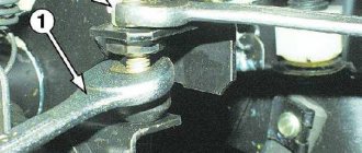
Lever jerking and engine beating
In order to diagnose the need for balancing the crankshaft, it is enough to take a closer look at how the gear shift lever behaves when moving. If it clearly plays both on the road and at idle, then it’s clearly time to start repairing the engine.
An additional sign that crankshaft adjustment is no longer possible is noticeable vibration of the engine at idle.
How to use?
Using a carriage puller to remove it is quite simple:
- remove the connecting rods using a connecting rod puller;
- if the carriage is square, then it is better to start on the left side;
- match the splines of the puller with the splines on your carriage;
- if the puller has a centering axis, screw it into the carriage shaft;
- Unscrew the carriage cup, then repeat the same steps on the other side.
Remember that most carriages have right-hand threads on the right and left-hand threads on the left. With the exception of Italians, where both cups have right-hand threads. Different companies have different tools. You may need an additional wrench to turn the carriage puller itself, or your puller may already have a handle. However, there are no very difficult or incomprehensible moments in using the puller, and anyone can figure it out.
Reasons for shaft failure
Most often, crankshaft imbalance occurs for the following reasons:
- Poor quality of the crankshaft bed and a number of components adjacent to the crankshaft;
- Structural anomalies in the metal from which the crankshaft is made;
- Mutual collision of a number of parts due to their mechanical, temperature and corrosion deformation;
- Errors made during the layout of the motor;
- Inaccurate shaft centering;
- Its planned operational destruction.
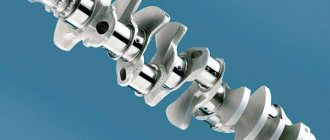
Principle of operation
Balancer shafts are installed in pairs on each side of the crankshaft and are complex cylindrical rods. Each balance shaft has a complex geometric shape. The shafts rotate in the opposite direction twice as fast as the crankshaft speed, thereby balancing the second-order inertial forces.
The shafts are installed in the engine crankcase on plain bearings (or needle bearings) and driven by a drive from the crankshaft. The bearings are connected to the engine lubrication system. They are the ones who experience the greatest load during the operation of the shafts. This causes their rapid wear, which is accompanied by noise and vibration.
Drive types
Balancing shaft drive
The most common type of balancer drive is a chain or toothed belt. The drive can also be a gear reducer or a combined version: a gear reducer plus a belt. To reduce vibrations of the shafts themselves, a spring damper is installed in the drive sprocket.
Balancing the crankshaft after engine overhaul
If a car enthusiast decides to replace the flywheel or its crown, as well as improve the performance of the clutch, then he cannot do without balancing the crankshaft.
Neglecting this repair standard will result in the engine shaking even when moving slowly, depriving the car of comfort and making it potentially dangerous.
Repair of balancer shafts
During operation of the internal combustion engine, the installed balancer shafts are subjected to heavy loads. The largest share of the load falls on the distant bearings, and therefore, greater wear of the balancing shafts occurs at the joints with the bearings and the bearings themselves. If the load on the balancing shafts exceeds the permissible limit, noise is heard, the internal combustion engine vibrates more, which also causes the balancer drive chain to break.
Full video recording of work in a car service center. Work on removing balance shafts D4CB, Hyundai Grand Starex.
The cost of repairing balancer shafts is quite expensive, and varies from service center to service center. Therefore, many car drivers, in order not to buy new ones or repair them, simply dismantle these balancing shafts and put plugs in the housing holes.
If you use balancing shafts in the engine, this complicates the design and increases the cost of repairs, and also leads to a decrease in the power of the internal combustion engine by approximately 15 hp.
If the balancer shafts are worn out, then, as a rule, engine power decreases and acceleration time increases. This is due to the fact that when the balancing shafts wear out, the phases are disrupted and the valve timing shifts later.
Standard Crankshaft Rebuilding Methods
Balancing a worn crankshaft is done by two well-established methods:
- Static, which is used when there are subtle deviations of parameters from the norm. During such repairs, the shaft is processed while stationary. Its heavier part is directed downwards, and the lighter part is balanced using weights fixed on its edge. Next, instrumental grinding of metal from a heavier area is carried out;
- Dynamic, which compares favorably with the previous one with increased processing accuracy. This method is used when there is a need to get rid of clearly visible unevenness. For this procedure, a special machine is used. The shaft fixed in it spins up to the required speed. Next, the laser method identifies the area where the greatest weighting occurs. It is this area that is subjected to grinding to remove excess metal.
Do-it-yourself flywheel balancing
The simplest solution is static balancing. Although it can be done in various ways, one of the simplest will be used below. It allows you to completely carry out the procedure without special tools.
To begin, it is important to determine the weight shift point. To do this, a metal rod is threaded through the center of the flywheel, which can withstand such weight without deformation.
If it still has a shaft in its design, then it can be used for this task. Next, you need to take two straight supports and secure them parallel.
Important! It is worth carrying out this procedure with a water level, because the slightest miscalculation can lead to erroneous conclusions during the diagnostic process.
Next, the flywheel is placed on these supports. After this, the heaviest side will move down, turning the axle. This will give you an idea of the approximate location of the center of gravity. By the way, for the same task you can replace the straight supports with a vice, clamping the shaft on which the part is located.
Next you need to take the following steps:
- Determine the weight shift point.
- Place the load on the opposite side.
- Carry out a re-diagnosis.
- If necessary, repeat the procedure.
Although craftsmen recommend hanging weights for balancing, often the excess metal is simply drilled out. The problem is that this not only reduces the overall weight of the flywheel, but can also simply render the part unusable.
You can also carry out balancing by weight if the part has a bearing. The idea is the same, there are several weights and a flywheel at an angle. Gradually rotating and determining the lack of weight, you need to place weights until the part is completely balanced. Many people consider this option more convenient, because the flywheel is not fixed anywhere and is constantly in limbo.
Services often carry out dynamic balancing of this element. It is more reliable and faster, and the result is an absolute balance of the part. This approach is recommended for everyone, but for this you need to go to a service center. It is almost impossible to carry out such a procedure on your own, because this requires a special stand with equipment. In addition, not only the flywheel is used here, but also the crankshaft and clutch.
So for doing the work yourself, static balancing is better suited. It allows you to quickly and quite well return the center of gravity to its place, using only available means. Although this is done faster and more accurately on a stand, this option is suitable for budget repairs.
And for a better understanding of the flywheel balancing procedure, it is recommended to watch this video. This shows a fixed part on which the center of gravity offset can be determined. This is the basis for further balancing procedures:
- Vibration of the clutch pedal after replacing the clutch
- Installing car seat ventilation
- Malfunctions of the ignition system of injection and diesel engines, operating principle
- Priora crankshaft pulley and oil seal
Balancing the crankshaft at home
If you wish, you can perform balancing right in your garage. This will save a lot of money on a visit to a car service center.
To successfully balance the crankshaft at home, you will need a special device. This is the machine in which the flywheel will be mounted.
The design of such a machine is extremely elementary. That is why even someone who has no experience in the production of tools will be able to assemble it with his own hands.
Clutch pressure plate with housing assembly
The disk is balanced statically in a dynamic mode when installed on the working surface and two diametrically located holes for attaching the casing to the flywheel, as well as by drilling holes with a diameter of 13.8 mm in the bosses under the springs to a depth of no more than 23 mm. The distance between the supporting surfaces of the disk and the casing should be 9.8 mm with a parallelism tolerance of these surfaces of 0.03 mm. The residual imbalance should be no more than 0.005 Nm. After balancing, the mounting holes must be marked. For any re-installation along the same holes, the imbalance should be no more than 0.009 Nm.
Making a frame and installing nuts
The first step is to make the frame base of the machine. Its dimensions are determined by the length of a particular crankshaft. At this stage, the master will need pipes and profiles.
- Having welded a frame from them, grooves for the studs should be made in a couple of its corners and in the center of the tube located opposite.
- Nuts are attached to these places by welding, the threads of which correspond to the width of the studs.
Operation of balance shafts
As mentioned earlier, the main reason for the failure of balancer shafts is natural wear. But a motorist can take several steps that will extend the life of this mechanism.
- The first step is not to drive aggressively. The sharper the power unit operates, the faster the shaft gears will fail. By the way, this also applies to a lot of other car parts.
- The second step is timely maintenance. Replacing the oil and oil filter will ensure high-quality lubrication of all contact elements, and installing a new drive belt (or chain) will allow the gears to rotate without additional loads.
Installation of locknuts and support posts
On the eve of balancing, the frame is set clearly horizontally. Once the alignment is complete, locknuts are screwed onto the nuts.
Then, next to each corner of the frame, grooves are made for four 25-centimeter rods, which will be the supports of the structure.
The final stage of machine assembly
Next, you should take four corners about a third of a meter long. Holes are made in them the same width as the diameter of the supports. Each pair of racks is crowned with a corner turned upside down, after which it is welded.
As a result, the car enthusiast will have something like a miniature gymnastic apparatus at his disposal. The crankshaft will be mounted on opposing U-shaped struts. You can start balancing.
What are balancer shafts
An internal combustion engine is a device of complex design based on the conversion of one energy into another. The more complex the device, in this case, the more cylinders the engine has, the stronger the vibrations and vibrations of individual parts and the engine as a whole are created.
The cylinders in the internal combustion engine are arranged differently:
- In-line engine diagram. This is one in which the axes of the cylinders are in the same plane.
- Opposite scheme. The cylinder axes are on the opposite side, that is, through 180 degrees.
- V-shaped internal combustion engine. The cylinder axes in B-shaped engines are located in different planes.
In all engines there are two types of forces:
- Balanced. Balanced forces are pressure force, friction force.
- Unbalanced. Unbalanced forces are the weight of the power drive, the force of inertia (that is, the reverse force).
Due to the fact that engines cannot operate without vibration, the designers came up with a part that minimizes increased vibration and oscillation values.
The balance shaft is a cylindrical rod with grooves on it. The balance shaft dampens second-order inertial forces. Second order forces in an internal combustion engine are not balanced by installing additional weights on the crankshaft cheek. First-order forces include the mass of the crank, the radius of its movement, angular velocity and angle of rotation. Second-order forces in an internal combustion engine include lambda, that is, the ratio of the crank radius to the length of the connecting rod.
Crankshaft balancing algorithm
After the machine is completed, the crankshaft should be balanced following the diagram below.
- The machine is set parallel to the horizon. Adjustment is carried out by tightening the racks.
- The crankshaft is placed on a level machine. If there are unevenness in the weight distribution, the shaft will rotate until the heaviest section moves straight down. Any unevenness found must be eliminated.
- To achieve this goal, it is necessary to remove excess metal in the most burdened part of the flywheel. To determine the weight of the metal to be drilled, miniature magnets are used. They are placed on the lightweight part of the flywheel. The magnets are fixed until the crankshaft, complete with spare parts, stops rotating and assumes a state of rest.
- With the shaft stationary, the magnets are removed and weighed. This determines the mass that needs to be removed to restore equilibrium.
- Next, it is necessary to grind off the metal from the flywheel, so that the mass of the chips is equivalent to the set mass of the magnets.
Engine IZH Planet 3, 4 and 5, disassembly, assembly for repair and tuning
When disassembling the engine, you must first drain the oil from it and remove it from the motorcycle frame; you must wash the engine thoroughly. To do this, it is advisable to use a high-pressure apparatus (car wash) with car shampoo. Having washed the engine and protected it from getting dirt inside, we proceed to disassembly.
We remove the right engine cover, remove the generator (by unscrewing the mounting bolts). Be careful not to damage the paronite gasket; remove the cover and disassemble the box. We take out the gears with the shafts and disassemble the shift mechanism, remove the control levers from the engine, and remove the clutch cover. We completely disassemble the clutch and remove the motor chain.
We disassemble the piston, remove the cylinder head (by unscrewing the fastening nuts), then remove the cylinder. After this, remove the piston from the crankshaft, first removing the retaining rings and carefully knocking out the piston pin.
We place the engine on its left side and, carefully without damaging the heads, unscrew the connection bolts using a powerful screwdriver. Then we knock out the centering halves of the crankcase half the length of the bushing.
Disassembled parts must be washed in gasoline and carefully inspected; damaged and faulty parts must be replaced with new ones. Clean the junction of the crankcase halves from old glue
On the oil seals (cuffs), pay attention to cracks and springs. Bearings should rotate easily without jamming and should not have any play
Having prepared the serviceable parts, we begin assembly.
We assemble the engine in the opposite order of disassembly. Be sure to heat the crankcase half to the same temperature, which makes assembly easier and preserves the crankcase surface from damage during pressing. The connection of the crankcase halves must be coated with BF-4 glue.
When installing the piston on the crankshaft, it is advisable to heat it to a temperature of 60 degrees, this will help when inserting the piston pin. During assembly, you also need to lubricate the cylinder mirror and piston pin with engine oil.