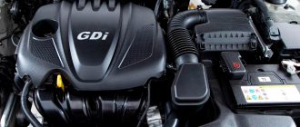
The fuel supply system of a gasoline engine ⭐ is designed to accommodate and purify fuel, as well as prepare a combustible mixture of a certain composition and supply it to the cylinders in the required quantity in accordance with the operating mode of the engine (except for engines with direct injection, the power system of which ensures the supply of gasoline to the chamber combustion in the required quantity and under sufficient pressure).
Gasoline , like diesel fuel, is a product of petroleum distillation and consists of various hydrocarbons. The number of carbon atoms included in gasoline molecules is 5 - 12. Unlike diesel engines, in gasoline engines the fuel should not be intensively oxidized during the compression process, as this can lead to detonation (explosion), which will negatively affect performance, efficiency and power engine. The knock resistance of gasoline is measured by its octane number. The larger it is, the higher the fuel’s detonation resistance and the permissible compression ratio. Modern gasoline has an octane number of 72–98. In addition to anti-knock resistance, gasoline must also have low corrosive activity, low toxicity and stability.
The search (based on environmental considerations) for alternatives to gasoline as the main fuel for internal combustion engines led to the creation of ethanol fuel, consisting mainly of ethyl alcohol, which can be obtained from plant biomass. There is a distinction between pure ethanol (international designation E100), containing exclusively ethyl alcohol; and a mixture of ethanol and gasoline (most often 85% ethanol with 15% gasoline; designation E85). In terms of its properties, ethanol fuel is close to high-octane gasoline and even surpasses it in terms of octane number (more than 100) and calorific value. Therefore, this type of fuel can be successfully used instead of gasoline. The only drawback of pure ethanol is its high corrosiveness, which requires additional protection against corrosion of fuel equipment.
The units and components of the fuel supply system of a gasoline engine are subject to high requirements, the main of which are:
- tightness
- fuel dosing accuracy
- reliability
- ease of maintenance
Currently, there are two main methods for preparing a combustible mixture. The first of them is associated with the use of a special device - a carburetor, in which air is mixed with gasoline in a certain proportion. The second method is based on forced injection of gasoline into the engine intake manifold through special nozzles (injectors). Such engines are often called injection engines.
Regardless of the method of preparing a combustible mixture, its main indicator is the ratio between the mass of fuel and air. When ignited, the mixture should burn very quickly and completely. This can be achieved only with good mixing of air and gasoline vapor in a certain proportion. The quality of the combustible mixture is characterized by the excess air coefficient a, which is the ratio of the actual mass of air per 1 kg of fuel in a given mixture to the theoretically necessary one, ensuring complete combustion of 1 kg of fuel. If there are 14.8 kg of air per 1 kg of fuel, then such a mixture is called normal (a = 1). If there is slightly more air (up to 17.0 kg), the mixture is lean, and a = 1.10... 1.15. When there is more than 18 kg of air and a > 1.2, the mixture is called lean. Reducing the proportion of air in the mixture (or increasing the proportion of fuel) is called enrichment. When a = 0.85... 0.90 the mixture is enriched, and when a < 0.85 it is rich.
When a mixture of normal composition enters the engine cylinders, it operates stably with average power and efficiency. When operating on a lean mixture, engine power is slightly reduced, but its efficiency is noticeably increased. On a lean mixture, the engine operates unstably, its power drops, and specific fuel consumption increases, so excessive leaning of the mixture is undesirable. When a rich mixture enters the cylinders, the engine develops the greatest power, but fuel consumption also increases. When running on a rich mixture, gasoline burns incompletely, which leads to a decrease in engine power, increased fuel consumption and the appearance of soot in the exhaust tract.
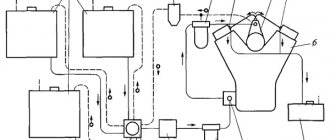
In general, the fuel system consists of the following elements:
- fuel tank (it stores a supply of fuel - gasoline or diesel fuel)
- fuel pump (takes fuel from the tank and sends it to the engine)
- Fuel level sensor (signals when refueling is required)
- fuel filter or filter system (clean fuel from mechanical impurities)
- air filter (cleanses the air of dust and other small particles)
- fuel line (a system of tubes and hoses that carries fuel to the engine)
- injection system (the device through which fuel enters the combustion chamber)
The fuel tank, or gas tank, is a metal or plastic container that is usually located under the trunk, although some cars have found some interesting places for it. If you cannot find the gas tank, it is best to find out its location in the manual or from a mechanic.
Inside the gas tank there is a small float that floats on the surface of the fuel, sending signals to the fuel level sensor on the instrument panel, so you can know when the next refueling is needed. Despite the fact that some cars run on diesel fuel, gasoline is now used in most cases, so by the word “fuel” we will mean it, although this is not entirely correct.
The fuel pump supplies gasoline (or diesel fuel) through a fuel line that runs under the bottom of the car from the tank to the carburetor or injectors for gasoline engines. In diesel engines, fuel is supplied to the high pressure pump (HHP) and then to the injectors. Older cars with carburetors use a mechanical pump that is powered by the engine. Fuel injection engines use an electric pump, which may be located inside the tank or somewhere nearby.
The fuel filter does exactly what its name suggests - it filters the fuel, that is, it cleans it. On its way through the gas line to the injectors or carburetor, the fuel passes through the fuel filter. A small mesh inside the filter traps dirt and rust that may be present in gasoline. Some machines have additional filters installed between the tank and the pump. It is important to change filters according to the factory maintenance schedule.
An air purifier purifies the air before mixing it with gasoline. In carburetor engines, the air cleaner is usually large and round with a tube protruding from the side to facilitate the intake of fresh air. On injection engines, a round air cleaner can be installed, or maybe a rectangular one.
To locate the rectangular air cleaner, follow the large air intake flare positioned as far away from the engine as possible.
Inside the air purifier there is an air filter that traps dirt and dust particles from the air taken in. If you often drive in dusty or sandy areas, you should periodically check the air filter and change it when it gets dirty (more often than the instruction manual requires).
Types of engine power systems
Depending on the fuel fluid used, engines, and therefore power systems, can be divided into three main types:
- gasoline;
- diesel;
- operating on gaseous fuel.
There are other types, but their use is very limited.
In some cases, the classification of power systems is made not by the type of fuel, but by the method of preparing and supplying the combustible mixture to the combustion chamber. In this case, the following types are distinguished:
- carburetor (ejector);
- with forced injection (injection).
Fuel level sensor
It is located on the pump module. By design, the fuel level sensor is a small system consisting of a float and a variable resistance mechanism with a nylon contact. Depending on the amount of contents in the fuel tank, the resistance of the element changes, which is indicated by an arrow on the instrument panel in the cabin.
It should be noted that the gasoline sensor is not negatively affected by low-quality fuel additives and does not break down due to frequent changes in temperature and pressure inside the tank.
Composition and functions of the fuel supply system
The main function of any fuel system is to supply the required amount of fuel from the tank to the combustion chamber at a certain point in time . Functionally, it is divided into two main systems:
- transportation of fuel, its filtration and creation of pressure in the system is carried out by mechanical and hydraulic devices;
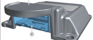
- calculation of the quantity and timing of fuel injection, as well as its distribution among the cylinders, is carried out by electronic devices.
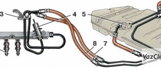
Vehicle fuel system
The fuel system includes the following elements:
- Tank is a sealed container for storing fuel.
- Pipelines (direct and return) – tubes and flexible hoses through which fuel is transported.
- Filters (coarse and fine) – perform cleaning from mechanical contaminants.
- Pressure regulator – necessary to ensure a given pressure level.
- The pump is usually submersible, driven by an electric motor.
- Injection pump – for direct injection systems (diesel engines).
- Fuel injectors.
Fuel injection scheme for injection cars
Currently, there are two types of injection systems:
- Single injection.
- With distributed injection.
In the first case, fuel is supplied to all cylinders using one nozzle. At the moment, single injection systems are almost never used on modern cars, which cannot be said about cars with distributed injection. The peculiarity of such injectors is that each cylinder has its own individual nozzle. This installation scheme is very reliable, and therefore all modern automakers use it.
Car fuel system operation
All the elements considered work in the following sequence... at the moment the engine starts, and on some cars at the moment the driver's door is opened, the fuel pump begins to work, creating the necessary operating pressure in the fuel system necessary to supply fuel to the engine.
As the fuel filter or filter system passes through the engine, the fuel is cleaned of various mechanical impurities. The air enters the combustion chamber or carburetor through an air filter, where it is also cleaned.
Depending on the design of the engine, the fuel-air mixture can be prepared both directly inside the combustion chamber of the engine cylinder, and before entering the cylinder, for example, in a carburetor. A combined method of preparing the fuel-air mixture is also possible.
After the fuel-air mixture is ready and enters the combustion chamber, it ignites. To continue to operate the engine, a constant supply of new portions of fuel is required, for which the fuel system is responsible.
Car device
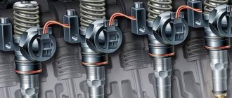
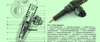
Injectors
This part is of particular importance for the car, since the quality of combustion of the fuel-air mixture, fuel consumption and power of the vehicle depend on its condition. The injector is a small mechanism with a solenoid valve. The latter is controlled by an ECU. When the control unit commands power to the injector winding, the closed ball valve opens and fuel passes through the plate into the injector nozzles. By the way, there are holes on the plate used to adjust fuel consumption. Fuel is injected by a nozzle into the channel of several intake valves. As a result, it evaporates before entering the combustion chamber of the engine.
Functions, structure and principle of operation
Each car is characterized by such a concept as “power reserve”. It is determined by the distance that a car can travel on a full fuel tank without additional refills. This indicator is influenced by a variety of factors: seasonal, weather and natural driving conditions, the nature of the road surface, the degree of vehicle load, the individual characteristics of the driver when driving, etc.). However, the main role in determining the “appetite” of a car is played by the power system and its proper operation.
The power system performs the following functions:
- fuel supply, cleaning and storage;
- air purification;
- preparing a special flammable mixture;
- supplying the mixture to the internal combustion engine cylinders.
The classic car power system consists of the following structural elements:
- a fuel tank designed to store fuel;
- a fuel pump that performs the functions of creating pressure in the system and forcing fuel supply;
- fuel lines - special metal tubes and rubber hoses for transporting fuel from the fuel tank to the internal combustion engine (and excess fuel in the opposite direction);
- fuel purification filter (or filters);
- air filter (to clean the air from impurities);
- devices for preparing the fuel-air mixture.
The power supply system has a fairly simple principle of operation: under the influence of a special fuel pump, fuel from the tank, having previously undergone a cleaning procedure with a fuel filter, is supplied through fuel lines to a device intended for preparing the fuel-air mixture. And only then the mixture is supplied to the engine cylinders.
Power System Options
The main types of fuel for internal combustion engines are gasoline and diesel fuel (“diesel fuel”). Gas (methane) also belongs to the types of modern fuel, but, despite its widespread use, it has not yet become relevant. The type of fuel is one of the criteria for classifying internal combustion engine power systems.
In this regard, power units are distinguished:
- gasoline;
- diesel;
- based on gaseous fuel.
But the most recognized among experts is the typology of engine power systems based on the method of fuel supply and preparation of the fuel-air mixture. Following this classification principle, we distinguish, firstly, the power supply system of a carburetor engine, and secondly, the power supply system with fuel injection (or an injection engine).
Carburetor
The carburetor system is based on the operation of a technically complex device - a carburetor. A carburetor is a device that prepares a mixture of fuel and air in the required proportions. Despite the variety of types, in automotive practice the most widely used is the float suction carburetor, the circuit diagram of which includes:
- float chamber and float;
- atomizer, diffuser and mixing chamber;
- air and throttle valves;
- fuel and air channels with corresponding jets.
The preparation of the fuel-air mixture in the carburetor is carried out according to a passive scheme. The movement of the piston during the intake stroke (first stroke) creates a rarefied space in the cylinder, into which air rushes, passing through the air filter and through the carburetor. It is here that the formation of a combustible mixture occurs: in the mixing chamber, in the diffuser, the fuel escaping from the atomizer is crushed by the air flow and mixed with it. Finally, through the intake manifold and intake valves, the combustible mixture is supplied to a specific engine cylinder, where at the required moment it is ignited by a spark from the spark plug.
Thus, the power system of a carburetor engine is a predominantly mechanical method of preparing the fuel-air mixture.
Fuel injection
The era of the carburetor is being replaced by the era of the injection engine, the power system of which is based on fuel injection. Its main elements are: an electric fuel pump (located, as a rule, in the fuel tank), injectors (or nozzle), and an internal combustion engine control unit (the so-called “brains”).
Positive and negative sides
Extensive experience in using such systems allows us to highlight weak and strong points. Advantages of an injection engine:
- Increased efficiency even on early systems. Thus, a reduction in consumption was achieved already on the Niva from VAZ, where consumption decreased by 40%. Today, fuel consumption in an injection engine is half that of a carburetor.
- Advanced internal combustion engine control capabilities.
- Improved dynamic parameters and increased power (on average by 10-15%).
- Simplified and fully automated motor starting.
- Maintaining XX speed.
- Possibility to do without manual adjustment of the fuel supply system. This is due to the fact that information is transmitted by the corresponding sensors (oxygen and crankshaft position).
- Carrying out self-diagnosis, which simplifies vehicle maintenance. In fact, systems with injectors from Euro 3 and above do not require periodic maintenance.
- Maintaining a fuel composition that is as close as possible to the stoichiometric indicator. As a result, the emission of hazardous substances is reduced and environmental friendliness is increased. For example, in the first generations the volume of carbon monoxide emissions was at the level of 20-30 grams / kWh, and in Euro 5 - 1.5 grams / kWh.
- Reduced hood height due to a more convenient location of the working mechanisms on the side of the engine rather than above it.
- Additional protection of the machine from intruders. Without receiving a command from the immobilizer, the ECU prohibits the supply of fuel to the internal combustion engine.
- No dependence on the position of the car in space. For example, in a car with a carburetor, difficulties arose with the supply of fuel even when climbing a 15-degree slope.
- The combustible mixture does not accumulate in the intake system, which eliminates ignition in the event of damage to the system.
- There is no dependence on atmospheric pressure, which allows you to operate the car even in the mountains and not worry about possible failures.
- Automation of the fuel supply system. The ECU takes care of all the fuel preparation work. For comparison, in engines with carburetors, the car owner had to make many settings himself.
Despite a number of positive qualities, one cannot fail to note the disadvantages of the injection power system. The main ones include:
- Increased production costs (this was true before 2005).
- More stringent requirements for fuel composition.
- Poor maintainability of components due to full automation.
- Fuel is supplied under high pressure, which can lead to fire in the event of an accident. For protection, a controller is used that stops the fuel supply in the event of an accident.
- The need for servicing at a special service station with diagnostic equipment. Accordingly, the cost of repairs also increases. At the present stage, this is not so relevant, because the services do not have a shortage of the necessary hardware and software.
- Dependence on battery and power level.
- The need for periodic cleaning of injectors and intake valves.
Malfunctions and service
During the operation of the vehicle, the vehicle's fuel system experiences loads that lead to its unstable operation or failure. The following faults are considered the most common.
Insufficient supply (or lack of supply) of fuel to the engine cylinders
Poor quality fuel, long service life, and environmental exposure lead to contamination and clogging of fuel lines, tank, filters (air and fuel) and technological openings of the combustible mixture preparation device, as well as breakdown of the fuel pump. The system will require repairs, which will consist of timely replacement of filter elements, periodic (every two to three years) cleaning of the fuel tank, carburetor or injector nozzles and replacement or repair of the pump.
Engine power loss
A malfunction of the fuel system in this case is determined by a violation of the regulation of the quality and quantity of the combustible mixture entering the cylinders. Troubleshooting involves the need to diagnose the combustible mixture preparation device.
Fuel leak
A fuel leak is a very dangerous phenomenon and is absolutely unacceptable. This malfunction is included in the “List of malfunctions...” with which the vehicle is prohibited from moving. The causes of the problems lie in the loss of tightness of the components and assemblies of the fuel system. Troubleshooting involves either replacing damaged system elements or tightening the fuel line fastenings.
Thus, the power system is an important element of the internal combustion engine of a modern car and is responsible for the timely and uninterrupted supply of fuel to the power unit.
I like3I don't like
What else is worth reading
VAZ 2109 generator device
The design of the chassis of the VAZ 2109
Intake manifold device
Fuel pump
Power system operating modes
Depending on the goals and road conditions, the driver can use different driving modes. They also correspond to certain operating modes of the power supply system, each of which has a special quality fuel-air mixture.
- The mixture will be rich when starting a cold engine. At the same time, air consumption is minimal. In this mode, the possibility of movement is categorically excluded. Otherwise, this will lead to increased fuel consumption and wear of power unit parts.
- The composition of the mixture will be enriched when using the “idling” mode, which is used when coasting or running the engine in a warm state.
- The mixture will be leaner when driving with partial loads (for example, on a flat road at medium speed in high gear).
- The mixture composition will be enriched at full load when the vehicle is moving at high speed.
- The mixture will be rich, close to rich, when driving under conditions of sharp acceleration (for example, when overtaking).
The choice of operating conditions for the power system, therefore, must be justified by the need to move in a certain mode.
Scheme, device and principle of operation for a diesel engine
Common rail fuel system diagram
Diesel fuel supply systems have their own characteristics. There are three types of structures:
- Common rail (or battery);
- With pump injectors;
- Separated.
Common rail
The most popular fuel system for diesel engines is battery (or common rail) . It meets higher environmental standards. This is ensured due to the independence of diesel injection processes from engine operating modes.
Structurally, the common rail diesel power system has two main circuits:
- Low pressure section - consists of a fuel tank, low pressure pump, pipelines and filter.
- High pressure section - consists of a high pressure fuel pump (HPF), a pipeline, a ramp (accumulator) and injectors.
The operating principle of the diesel fuel system is the following sequence:
- The low pressure pump forces diesel from the fuel tank into the pipeline.
- Passing through the pipeline through coarse and fine filters, diesel is supplied to the high pressure pump.
- The fuel injection pump supplies fuel to the injectors, which are used to inject fuel into the cylinders.
- Air is supplied simultaneously with fuel injection.
Split and unit injector
Pump-injector
The divided fuel system consists of a fuel tank, pipelines, injection pump and injectors. In this case, the pump and nozzles are connected by long pipelines designed for high pressure. The divided circuit is actively used in the domestic automotive industry, since it is characterized by low cost and simplicity of design .
In turn, a pump injector is a device that simultaneously creates the required level of pressure and injects fuel. It is located in the cylinder head and is driven by a cam mechanism. The forward and return lines are implemented as channels located directly in the block head.
The operating pressure with this scheme is up to 2,200 bar.
This method has an important drawback - it is characterized by the dependence of pressure on the engine operating mode.
Node device
Oddly enough, the layout of the diesel fuel system is very similar to its gasoline counterparts. The only difference is the injection system. But more on that a little later, but for now let’s look at the design of this unit.
So, the fuel system diagram assumes the presence of the following structural elements:
- Gas tank. This element can be made of thin sheet steel or very dense polypropylene. On cars and SUVs, the gas tank is installed on the bottom. On trucks, in particular truck tractors, it is mounted on special supports between the rear and front axles (on the left or right side). The fuel tank has a valve that prevents fuel from leaking when the vehicle rolls over.
- Filler cap. This part has a special thread that allows air to enter when unscrewing it. And to make it convenient for the driver to unscrew the cover, it has a special ratchet mechanism. This element also contains a safety valve, which, if the car gets into an accident, relieves the pressure inside the tank. By the way, on modern cars with Euro-2 or higher exhaust standards, fuel vapors are not allowed to enter the atmosphere. Therefore, to catch them, a special carbon adsorber is installed in the system.
- Fuel pump. This element is electrically driven and is located inside the tank. The pump is controlled by an electronic control unit. The part is activated using a special relay. When the driver turns on the ignition, it works for some time (no more than 4-5 seconds), thereby providing the necessary pressure in the system to start the engine. It is also worth noting that the pump is cooled by gasoline. Therefore, working with an empty tank can damage it.
- Fuel filter. Often a car is equipped with two types of these elements. This is a mechanism for fine and coarse fuel purification. The strainer is mounted on the fuel pump housing. The essence of its work is to trap contaminants that can enter the engine and form excess carbon deposits. Also, a working filter significantly increases the service life of the pump, preventing its frequent contamination. The fine cleaning mechanism is located on the underbody, in front of the rear suspension of the car. This type of filter is based on a paper element that is capable of trapping small particles of dirt, resins and deposits that can damage the fuel system.
Fuel return line (“return”)
Fuel systems
As a rule, the fuel pump has a constant capacity, that is, it pumps fuel from the tank into the ramp under constant pressure . The engine operates in different modes, consuming different amounts of fuel, depending on its load. Thus, it becomes necessary to control the pressure and amount of fuel in the fuel rail.
This is done by the fuel pressure regulator, which drains excess fuel back into the tank through the fuel return line , the so-called “return”. Currently, there are two types of fuel systems, differing in the presence or absence of a fuel return line (return line).
- Fuel supply system with return line . Fuel that is not injected by the injector is excess fuel and it returns back to the tank through the regulator, which is located on the fuel rail, and the return line. In this way, constant pressure is maintained in the fuel manifold.
- Fuel system without return line . The fuel pressure regulator in such systems is usually installed in the submersible fuel pump module. Excess fuel supplied by the pump is returned back to the tank through a short return line. In this case, only the amount of fuel that is injected by the injectors is supplied to the fuel rail. This system has the following advantages: lower cost and less heating of the fuel in the tank.
Sources
- https://autodromo.ru/articles/toplivnaya-sistema-avtomobilya-sistema-podachi-topliva-ustroystvo-naznachenie-princip
- https://ZnanieAvto.ru/toplivo/sistema-pitaniya-dvigatelya-avtomobilya.html
- https://topdetal.ru/stati/kakie_byvayut_vidy_sistem_pitaniya_dvigatelya/
- https://TechAutoPort.ru/dvigatel/toplivnaya-sistema/toplivnye-sistemy-benzinovyh-i-dizelnyh-dvigateley.html
[collapse]
Additives and their use
In conclusion, I would like to talk a little about additives for flushing injectors, in which systems should they be used and in which should they not be used?
Firstly , the use of any additives for cleaning injectors, whether distributed or direct injection, must be done at your own peril and risk. There are a lot of fakes, a lot of deception, and you can “crash” the injector even worse than cleaning it.
Secondly , distributed injection is less susceptible to an aggressive environment, because it is located in the intake manifold, there are no high temperatures, and therefore such injectors can run for 70 - 80,000 without cleaning. You can add fuel additives to them, which (if they work) can easily “wash away” the deposits on them. THIS IS REASONED HERE!
Thirdly , direct injection, as I already wrote - that the injectors are in an aggressive environment! All sorts of deposits are simply baked on them (which settles both in the cylinders and on the spark plugs). It is difficult to wash it off, and with the use of some additives - so it is advisable to remove them and clean them at a service station, on a stand, and let them demonstrate their performance to you. YES it is more expensive, but I told you that such a fuel supply system is more expensive to operate. I WOULD NOT USE ADDITIVES TO CLEAN THEM.
That’s it, now there’s a detailed video version of the article, for those who didn’t understand, I tried to make it simple.
Read our AUTOBLOG, there will be many more useful articles and videos.
Similar news
- Engine without valve springs. Really a revolution in the engine industry...
- Efficiency of an internal combustion engine. Approximately how much is...
- Scratches on the car body