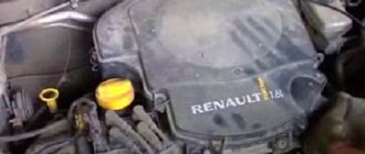
The domestic car of the especially small class VAZ with the index 1111 (11113) is the only AvtoVAZ model from the entire family that was equipped with a two-cylinder engine. At the same time, during the creation of this motor, the designers tried to unify this motor as much as possible with other types, in particular from VAZ-2108-21099 cars. The result of this work was that the principle of operation of the units and many elements of these installations are the same and interchangeable (for example, CPG), the only difference is in quantity.
Adjusting the clearances in the valve drive of VAZ "OKA" 1111 1988-2008
To compensate for the thermal expansion of the valve, a gap is structurally specified between the end of the valve stem and the camshaft cam.
With an increased gap, the valve will not open completely, and with a decreased gap, it will not close completely. The gap is measured with a feeler gauge on a cold engine (at a temperature of +20 ° C) between the camshaft cam (the cam should be directed upward from the pusher) and the valve pusher adjusting washer. The nominal clearance for the intake valve is (0.2±0.05) mm, for the exhaust valve - (0.35±0.05) mm. The gaps are adjusted by selecting the thickness of the shims. Spare parts are supplied with washers with a thickness of 3 to 4.5 mm every 0.05 mm.
Counting from the camshaft drive belt: the 1st and 4th valves are exhaust, the 2nd and 3rd are intake.
The order in which the gaps are adjusted does not matter.
Rotate the crankshaft only by the bolt securing the pulley to it (do not turn the crankshaft by the camshaft pulley).
It is inconvenient to turn the crankshaft by the bolt securing the pulley to it, so to set the camshaft cams to the upper position, engage any gear (preferably fourth) and slowly roll the car until the cams take the desired position. If it is not possible to roll the car, hang up any front wheel and, having engaged any gear, align the cams by turning the hung wheel.
You will need: a “10” wrench, a wrench for wheel nuts, a screwdriver, a set of feeler gauges, a device for adjusting the gaps in the valve drive, tweezers or pliers with narrow jaws, a micrometer (if necessary).
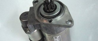
This is what the device for adjusting the gaps in the valve drive looks like:
1 – device for compressing valve springs; 2 – tube for VAZ (4-cylinder engine); 3 – tube for Oka (2-cylinder engine); 4 – clamp
If there is no special device for the Oka, you can use the device for front-wheel drive VAZ models. In this case, instead of the tube supplied with the device, select a tube of the same diameter and length of at least 21 mm. Drill two holes in it with a diameter of about 10 mm at a distance of 17.8 mm or drill an additional hole in tube 2 supplied with the device according to the specified dimensions (in this case the device can only be used to adjust the Oka gaps).
1. Remove the air filter (see “Removing and installing the air filter”).
2. Close the carburetor with a plug or a clean rag.
3. Remove the cylinder head cover (see “Cleaning the crankcase ventilation system”).
4. Turn the crankshaft with a wheel nut wrench by the bolt securing the generator drive pulley through the hole in the right wheel niche (to make it easier to turn the shaft, you can unscrew the spark plugs) so that.
5. . The marks on the generator drive pulley and on the front camshaft drive cover coincide. In this case, you can adjust the clearances in the drive of either the 1st and 2nd, or the 3rd and 4th valves.
Please note that there are two marks on the cover. In this case, you need to focus on long mark 1. Mark 2 is marked on the inside of the pulley. For convenience, duplicate it, for example with a felt-tip pen, on its outer part.
6. Measure the gaps in the valve drive of one of the cylinders with a flat feeler gauge. Replace the adjusting washers of those valves whose clearances differ from the nominal ones. Record the measured clearances.
7. To make it easier to remove the adjusting washer, two grooves are made in the pusher. Using a screwdriver, turn the pusher by the groove so that it is convenient to pry off the washer. For ease of operation, remove oil from the top of the cylinder head around the valve tappets.
8. Install a special device on the head cover mounting studs.
9. Place the washers on the studs, turning them over so as not to crush the flange on them.
10. Secure the device with the nuts securing the cylinder head cover.
11. By pressing down the lever of the device, press down the pusher on which the adjusting washer is being replaced. Then.
12. . insert the clamp under the camshaft so that.
13. . the protrusion on the latch 1 fixed the pusher 2 in the recessed position.
14. Using a screwdriver, pry up the adjusting washer and.
15. . using, for example, tweezers, remove the washer from the pusher.
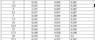
16. Write down the thickness of the shim, the value of which is marked on one of its sides.
If the inscription is not visible, measure the thickness of the washer with a micrometer.
17. Calculate the thickness of the new shim using the formula (all values in mm):
where H is the thickness of the new washer;
A is the value of the measured gap;
For example (for inlet valve):
A = 0.26 mm, B = 3.75 mm, C = 0.2 mm, then H = 3.75 + 0.26–0.2 = 3.81 mm.
Within the tolerance of the gap (±0.05 mm), we select the closest washer in thickness - 3.8 mm.
18. Install a new washer in the pusher with the thickness calculated according to the formula with the inscription facing down (towards the pusher). Press the pusher with the tool and remove the lock. Check the clearance again and repeat the adjustment if necessary.
19. Rotate the crankshaft one revolution (360°) and adjust the valve clearances of the other cylinder in the same order. Then fill the top of the cylinder head with oil if it has been removed.
20. Check the condition of the head cover gasket and replace it if necessary. Install all removed parts in the reverse order of disassembly.
Source
VAZ 11113
We measure and adjust the thermal clearances of the valve mechanism on a cold VAZ 11113 engine.
- Remove the air filter housing (see "Removing the air filter housing"). Remove the front timing belt cover (see "Adjusting the tension of the timing belt").
- Use a Phillips screwdriver to loosen the clamp securing the crankcase ventilation supply hose.
- Remove the hose
- Using a 10mm wrench, unscrew the two nuts securing the cylinder head cover (valve cover).
- Remove the washers and rubber sealing bushings installed in the holes of the valve cover.
- After disconnecting the crankcase ventilation outlet hose from the carburetor fitting, remove the valve cover.
- Remove the valve cover gasket.
The procedure for checking and adjusting the clearances in the valve drive mechanism is as follows.
- Turn the crankshaft clockwise until the timing marks on the camshaft timing belt and rear timing belt cover align (see “Replacing the timing belt”).
- Then we turn the crankshaft another 40-50° (2.5-3 teeth on the camshaft pulley).
- In this position of the shafts, use a feeler gauge to check the gap at the first camshaft cam. The clearance between the camshaft cams and shims should be 0.20 mm for intake valves and 0.35 mm for exhaust valves. The clearance tolerance for all jaws is +0.05 mm.
- If the gap differs from the norm, then install a device for adjusting the valves on the studs of the camshaft bearing housing. We introduce the “fang” of the device between the cam and the pusher. We rotate the pusher so that the slot in its upper part faces forward (along the direction of the car).
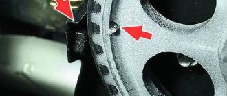
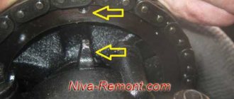
- By pressing down on the lever of the device, we recess the pusher with the “fang” (Fig. 1) and install a clamp (Fig. 2) between the edge of the pusher and the camshaft, which holds the pusher in the lower position.
Rice. 1. Recessing the valve pusher when replacing the adjusting washer: 1 – device; 2 – pusher.
Rice. 2. Fixing the valve pusher when replacing the adjusting washer: 1 – clamp; 2 – adjusting washer.
26. Calculate the thickness of the new shim using the formula:
(all values in mm)
where H is the thickness of the new washerB is the thickness of the old washerA is the value of the measured gapC is the nominal gap
For example (for intake valve): A = 0.26 mm, B = 3.75 mm, C = 0.2 mm, then H = 3.75 + 0.26 – 0.2 = 3.81 mm. Within the tolerance of the gap (±0.05 mm), we select the closest washer in thickness - 3.8 mm.
27. Install a new washer into the pusher with the thickness calculated according to the formula with the inscription facing down (toward the pusher). Press the pusher with the tool and remove the lock. Check the clearance again and repeat the adjustment if necessary.
28. Turn the crankshaft one revolution (360°) and adjust the valve clearances of the other cylinder in the same order. Then fill the top of the cylinder head with oil if it has been removed.
26. Calculate the thickness of the new shim using the formula:
(all values in mm)
where H is the thickness of the new washer B is the thickness of the old washer A is the value of the measured gap C is the nominal gap
For example (for intake valve): A = 0.26 mm, B = 3.75 mm, C = 0.2 mm, then H = 3.75 + 0.26 – 0.2 = 3.81 mm. Within the tolerance of the gap (±0.05 mm), we select the closest washer in thickness - 3.8 mm.
27. Install a new washer into the pusher with the thickness calculated according to the formula with the inscription facing down (toward the pusher). Press the pusher with the tool and remove the lock. Check the clearance again and repeat the adjustment if necessary.
28. Turn the crankshaft one revolution (360°) and adjust the valve clearances of the other cylinder in the same order. Then fill the top of the cylinder head with oil if it has been removed.
The domestic car of the especially small class VAZ with the index 1111 (11113) is the only AvtoVAZ model from the entire family that was equipped with a two-cylinder engine. At the same time, during the creation of this motor, the designers tried to unify this motor as much as possible with other types, in particular from VAZ-2108-21099 cars. The result of this work was that the principle of operation of the units and many elements of these installations are the same and interchangeable (for example, CPG), the only difference is in quantity.
Features of the timing device
The same applies to the gas distribution mechanism. The essence of the work is identical, as well as the design, but the VAZ Oka has 11113 distributors. the shaft has only 4 cams. Therefore, the maintenance of the power plant of a small car is no different from the VAZ-2108.
The Oka uses a gas distribution mechanism with an overhead camshaft, which is installed in the engine cylinder head. This made it possible to abandon a number of components (bars, rocker arms). In this design, the camshafts. shafts act on the valves through pushers. In this case, it is necessary to have a thermal gap between the component elements (cam-pushrod-valve heel), which compensates for the change in geometric parameters occurring due to expansion of the metal as a result of heating.
Lada Oka almost like 08 › Logbook › Valve adjustment))
Today I finally adjusted the valves. I was already sick of this noise, I couldn’t hear the engine behind it) I started it in the morning when I woke up. I warmed up the car in a clever way - I stuck a thermocouple under the valve cover, and when the cylinder head warmed up to 20 degrees, I turned off the engine and began to measure the gaps.
1 exhaust valve - 0.45 clearance 2 intake valve - 0.2 clearance 3 intake valve - 0.2 clearance 4 exhaust valve - 0.4 clearance
As you can see, only one valve required adjustment. But if I climbed, then turn everything back) I decided to tighten the valves to the lower tolerance limit. That is, make the intake 0.15, exhaust 0.3
I pulled out the adjusting washers without any tools, using only a 19 mm wrench, a knife and a thin screwdriver) I turned the crankshaft with a wrench (it’s better to unscrew the spark plugs, it will be easier to rotate several times), the camshaft clamped the valve I needed, and with the blade of a knife turned on its edge I fixed the pusher. Everything turned out very easily and quickly, and most importantly, minimal costs)
Here are the results of what I measured, what was in the engine and what I considered buying:
Then I went shopping to look for washers. It turned out that this is a shortage (Although the chisels seem to be used a lot on the road. I found them only on the market, the washers seemed to be factory ones, with increments of 0.05. I bought 4 pieces with adjustments for each valve. The washers darkened a little over time, polished them at home with 1200-grit sandpaper and measured them with a micrometer - everything the dimensions corresponded to the inscriptions, which was pleasing. By the way, the washer costs 50 rubles, it’s kind of expensive, but there wasn’t much to choose from(
The last step was to put everything back together in reverse order and turn the engine over several times to make sure nothing was sticking. I started it, let it warm up, the idle values disappeared completely after adjustment)) About an hour after that, when the engine cooled down, I went to check the gaps again. All valves corresponded to my calculations) Intake 0.15, exhaust 0.3, everything was as I wanted.
At the end, I adjusted the carb and tightened the timing belt, otherwise it was too loose.
The result is that there is no rattling at all.
, the engine runs very quietly. Only now the timing belt pulley is straining and you can hear its howling. Although I changed it not so long ago (I noticed a good increase in power after 3 thousand, but the filling of the cylinders has improved. In general, one positive so far)
The procedure for adjusting the valves oka 1113
The same applies to the gas distribution mechanism. The essence of the work is identical, as well as the design, but the VAZ Oka has 11113 distributors. the shaft has only 4 cams. Therefore, the maintenance of the power plant of a small car is no different from the VAZ-2108.
The Oka uses a gas distribution mechanism with an overhead camshaft, which is installed in the engine cylinder head. This made it possible to abandon a number of components (bars, rocker arms). In this design, the camshafts. shafts act on the valves through pushers. In this case, it is necessary to have a thermal gap between the component elements (cam-pushrod-valve heel), which compensates for the change in geometric parameters occurring due to expansion of the metal as a result of heating.
But during engine operation, wear occurs on the surfaces of the cams, pushers and heels as a result of friction, which causes the thermal gap to change. Moreover, it is not necessary that it will increase; it also happens that the gap decreases. This often happens due to low-quality oil, which leads to the appearance of deposits on the working surfaces of the timing belt.
As a result of a change in the thermal gap, a violation of the valve timing occurs, which is why the power plant loses power (which the Oka already has “sparsely”), fuel consumption increases, and dynamics decrease. And all because the valves either open insufficiently (increased clearance) or do not fit tightly to the seats (reduced clearance).
To compensate for changes in the thermal gap, the VAZ-1111 uses special adjusting washers, which are placed in a special seat in the pusher. That is, the contact of the camshaft cam occurs not with the pusher, but with the installed washer.
In order for the thermal gap to meet the standard, periodic adjustment of the valves on the Oka is required. Due to the design features of the timing belt, the entire process boils down to installing washers of the required thickness.
Lada Oka 2005, petrol engine 0.7 l., 33 l. p., front drive, manual transmission — scheduled maintenance
Participate in the discussion can only registered users.
Lada Oka almost like 08 › Logbook › Valve adjustment))
Today I finally adjusted the valves. I was already sick of this noise, I couldn’t hear the engine behind it) I started it in the morning when I woke up. I warmed up the car in a clever way - I stuck a thermocouple under the valve cover, and when the cylinder head warmed up to 20 degrees, I turned off the engine and began to measure the gaps.
1 exhaust valve - 0.45 clearance 2 intake valve - 0.2 clearance 3 intake valve - 0.2 clearance 4 exhaust valve - 0.4 clearance
As you can see, only one valve required adjustment. But if I climbed, then turn everything back) I decided to tighten the valves to the lower tolerance limit. That is, make the intake 0.15, exhaust 0.3
I pulled out the adjusting washers without any tools, using only a 19 mm wrench, a knife and a thin screwdriver) I turned the crankshaft with a wrench (it’s better to unscrew the spark plugs, it will be easier to rotate several times), the camshaft clamped the valve I needed, and with the blade of a knife turned on its edge I fixed the pusher. Everything turned out very easily and quickly, and most importantly, minimal costs)
Here are the results of what I measured, what was in the engine and what I considered buying:
Then I went shopping to look for washers. It turned out that this is a shortage (Although the chisels seem to be used a lot on the road. I found them only on the market, the washers seemed to be factory ones, with increments of 0.05. I bought 4 pieces with adjustments for each valve. The washers darkened a little over time, polished them at home with 1200-grit sandpaper and measured them with a micrometer - everything the dimensions corresponded to the inscriptions, which was pleasing. By the way, the washer costs 50 rubles, it’s kind of expensive, but there wasn’t much to choose from(
The last step was to put everything back together in reverse order and turn the engine over several times to make sure nothing was sticking. I started it, let it warm up, the idle values disappeared completely after adjustment)) About an hour after that, when the engine cooled down, I went to check the gaps again. All valves corresponded to my calculations) Intake 0.15, exhaust 0.3, everything was as I wanted.
At the end, I adjusted the carb and tightened the timing belt, otherwise it was too loose.
The result is that there is no rattling at all.
, the engine runs very quietly. Only now the timing belt pulley is straining and you can hear its howling. Although I changed it not so long ago (I noticed a good increase in power after 3 thousand, but the filling of the cylinders has improved. In general, one positive so far)
Adjusting valves oka 1111
Your request on the topic of adjusting the valves of the VAZ 11113 Oka with your own hands video has been processed. The best repair video and instructions on how to repair can only be found on our website. The presented videos are published with photos. Enjoy watching.
Owner reviews: after-sales service - competitors will die from shock
Category: Video instructions
Published by admin: at the request of Moses
VAZ 1111 | Checking/adjusting valve clearance
Checking/adjusting valve clearance
Engines E1, EZ, E5, VZ, V5, V6 until 9/89, PN
To compensate for various thermal expansions, the distribution mechanism must have a certain valve clearance.
If the gap is too small, the valve timing changes, compression becomes unsatisfactory, engine power decreases, and the engine runs unstable. In extreme cases, valves or valve seats may become distorted.
If the gap is too large, very strong mechanical noise appears, the valve timing changes, due to the valve opening time being too short, the engine does not develop maximum power, and the engine runs unstable. Valve adjustment achieves the desired result only if the valves seal perfectly, do not have unacceptable play in the guides and are not knocked down at the ends of the stems.
Valve clearance is checked and adjusted as part of maintenance, see Section Maintenance technology, tools and workplace equipment, and after repair, or if noise appears in the distribution mechanism. The valve clearance is checked and adjusted on a warm engine. The operating condition of the engine is achieved by driving 10-15 km under normal conditions, when the temperature gauge is in the middle region.
| Adjustment | high school graduation | |
| E1, EZ, E5 | 0.25 mm | 0.30 mm |
| VZ, V6 | 0.30 mm | 0.30 mm |
| PN (diesel) | 0.20 mm | 0.30 mm |
When should adjustment be made?
The valve clearance on the Oka, according to the manufacturer’s recommendations, should be adjusted every 30 thousand km. But this is far from an accurate indicator, since much depends on operating conditions. Thus, lubricants, fuel, climatic conditions, features and intensity of use of the car can significantly affect the operation of the timing belt, and work on adjusting the thermal gap will have to be carried out earlier.
There are a number of signs indicating a change in the thermal gap:
- Increased engine noise (the sound of the unit is similar to a diesel unit);
- Power drop;
- Poor launch;
Some note that fuel consumption also increases. This is true, but the Oka uses a carburetor power system (except for the latest models equipped with a Chinese 3-cylinder unit), so it is simply unrealistic to determine the amount of fuel consumed, and such a sign of a change in the thermal gap can be ignored.
This type of maintenance can be done with your own hands, since the whole process is not complicated, but you need to know how to properly adjust the valves on the Oka.
The main thing you need to know is what valve clearance on the Oka is considered normal. Here it all depends on what kind of valve it is: for the intake valve it is 0.2 mm (an error of 0.05 mm is allowed), and for the exhaust valve it is 0.35 mm (the same error).
Adjusting Oka valves
The domestic car of the especially small class VAZ with the index 1111 (11113) is the only AvtoVAZ model from the entire family that was equipped with a two-cylinder engine. At the same time, during the creation of this motor, the designers tried to unify this motor as much as possible with other types, in particular from VAZ-2108-21099 cars. The result of this work was that the principle of operation of the units and many elements of these installations are the same and interchangeable (for example, CPG), the only difference is in quantity.
Main video: adjusting the valves of the VAZ 11113 Oka with your own hands video
More video: adjusting oka valves
Currently reading about French cars
© Repair of foreign cars and our cars
2014 – 2022 Copying materials from a web resource without consent from the site administration is strictly prohibited.
- Posts: 6
- From: Sukhoi Log city
- Oka 11113
February 21, 2011, 09:23 #1 123
Good day everyone! Guys of Okavoda, help me out. The question is, what are the optimal valve clearances for an Oka? The thing is, the car ran up to 150 km/h, then it accidentally overheated and the piston partitions fell out. I've rebuilt the engine, but I can't find the optimal clearances. I set the intake to 0.20, exhaust to 0.35, it runs fine. But it eats like a steam locomotive, I set it to 0.15 and 0.30, the power increases, consumption is more economical, and the speed is maximum 110 and the engine works like it’s wearing out at crazy speeds that is about to fly out from under the hood. In general, we want to return the old regime and speed and economy. Thank you in advance for your response!
- Posts: 84
- From: Rudny
- Lada Niva
February 21, 2011, 09:35 #2 123
Set the intake to 0.15 and exhaust to 0.25! this is a better option!
- Posts: 2322
- From: Warsaw, Poland.
- Nissan Pathfinder
February 21, 2011, 10:53 #3 123
and are you sure that the problem is not in the marks on the timing belt, according to the description you missed the mark.
- Posts: 6
- From: Sukhoi Log city
- Oka 11113
February 21, 2011, 14:40 #4 123
Eugene! Good afternoon. I couldn't fly by a tooth. The marks looked the same, the only thing is that before the engine was overhauled, the distributor was completely unscrewed to +. By the way, after I overhauled it, detonation appeared, if I put small gaps, the detonation disappears. But there is a possibility of valve burnout.
- Posts: 2322
- From: Warsaw, Poland.
- Nissan Pathfinder
February 21, 2011, 15:26 #5 123
180xot, 21 February 2011, 14:40
Eugene! Good afternoon. I couldn't fly by a tooth. The marks looked the same, the only thing is that before the engine was overhauled, the distributor was completely unscrewed to +. By the way, after I overhauled it, detonation appeared, if I put small gaps, the detonation disappears. But there is a possibility of valve burnout.
Do-it-yourself oka valve adjustment
+7 (812) 924 3 942
+7 (911) 924 3 942
Adjusting the Oka carburetor – Do-it-yourself adjustment of the Oka 11113 carburetor
How to adjust the carburetor on oka 1111
The need to completely disassemble the carburetor arises in cases where washing and adjustment with partial disassembly do not restore its functionality.
Carburetors of models 1111 and 11113 have the same design. They differ only in some calibration data (Table 2.3). Carburetor mod. 11113 has a second chamber main fuel jet marking of 102.5 (instead of 95 for model 1111), a main air jet diameter of 1.70 mm (instead of 1.80) and an idle speed system fuel jet marking of 42 (instead of 41).
It should be taken into account that at the manufacturer the initial adjustments of each carburetor are selected individually, since the manufacturing accuracy is low. Therefore, carburetors of both models may have the same fuel jets for the idle system - pay attention to the marking of this jet in the carburetor of your car.
You will need: keys “7”, “8”, “11” and “13”, a set of drills Zh1.1–1.5 mm, copper wire Zh0.2–0.25 mm, screwdrivers, pliers with long thin lips.
1. Remove the carburetor from the car (see “Removing and installing the carburetor”).
2. Remove the four screws securing the starter cover.
3. Remove the cover along with the spring.
4. Carefully remove the trigger diaphragm and rod.
5. Remove the four screws securing the accelerator pump cover.
6. Remove the cover with the drive lever and accelerator pump diaphragm.
6. Remove the spring.
7. Remove the plastic plug from the adjusting screw housing (if it was not removed earlier when adjusting the idle speed).
8. Unscrew the adjusting screw and remove it from the housing.
9. Replace the torn or loose o-ring of the adjusting screw.
10. Remove the two screws securing the adjusting screw housing.
11. Remove the housing and sealing gasket. Replace a torn or heavily compressed gasket.
12. Remove the five screws securing the carburetor cover and carefully remove the carburetor cover, being careful not to damage the gasket.
13. Remove the cover gasket. Replace a torn or heavily compressed gasket.
14. Unscrew the fuel valve from the cap.
15. Inspect the valve's copper O-ring. Replace a badly compressed ring.
16. If necessary, unscrew the choke control lever shaft.
17. Remove the choke control lever, lever retaining ball and spring. Do this carefully; the spring-loaded ball may get lost. Replace the broken spring.
18. Carefully pry with a screwdriver.
19. . remove the accelerator pump nozzle housing.
20. Replace a torn or loose o-ring.
21. If necessary, pry with two screwdrivers and remove sprayer 1 from the first chamber and sprayer 2 from the second chamber.
Please note: sprayer 1 of the first chamber, unlike sprayer 2 of the second chamber, has a transverse pin, and spring clamps are inserted into the ends of the legs of the sprayers. Don't lose them.
22. Using a screwdriver, remove the float axis lock.
23. Remove the float along with the axle from the carburetor body.
24. Remove the float shaft from the bracket.
25. Remove the main air jets from the carburetor body. Please note: the jets have different markings. Don't mix them up.
26. Remove the jets with emulsion tubes from the housing.
27. Unscrew the solenoid valve if it was not unscrewed when removing the carburetor.
28. Remove the idle fuel jet from the valve.
29. Using a screwdriver, remove the locking plate of the main fuel jet plugs.
30. Remove the plugs.
Please note: copper sealing washers are installed under the plugs. Replace heavily compressed washers.
31. Remove the main fuel jets from the carburetor body.
Pay attention to the markings of the jets. For carburetors mod. 11113 she is different. Don't mix up the jets.
32. Unscrew the fuel nozzle holder for the second chamber transition system.
33. Remove the fuel jet of the second chamber transition system from the holder.
34. Remove the second chamber intermediate throttle lever return spring.
35. Remove the two screws securing the throttle body to the carburetor body.
36. Separate the carburetor and throttle bodies and remove the heat-insulating gasket.
37. The accelerator pump diaphragm should not have tears or delaminations. Pusher 1 of the diaphragm support cup must move without jamming in the body of cup 2 and clearly return to its original position using a damping spring. The pusher damping spring must have no permanent deformation and must be significantly stiffer than the diaphragm return spring, otherwise the pump flow will sharply decrease. To compare the stiffness of the springs, squeeze the central cup of the diaphragm with the return spring attached to it in the operating position between your index finger and thumb. If the spring elasticity ratio is optimal, the return spring should first compress until the coils touch, and only after that the diaphragm pusher should begin to move in the cup. If the damping spring weakens, replace the diaphragm assembly as it is not removable.
When should adjustment be made?
The valve clearance on the Oka, according to the manufacturer’s recommendations, should be adjusted every 30 thousand km. But this is far from an accurate indicator, since much depends on operating conditions. Thus, lubricants, fuel, climatic conditions, features and intensity of use of the car can significantly affect the operation of the timing belt, and work on adjusting the thermal gap will have to be carried out earlier.
There are a number of signs indicating a change in the thermal gap:
- Increased engine noise (the sound of the unit is similar to a diesel unit);
- Power drop;
- Poor launch;
Some note that fuel consumption also increases. This is true, but the Oka uses a carburetor power system (except for the latest models equipped with a Chinese 3-cylinder unit), so it is simply unrealistic to determine the amount of fuel consumed, and such a sign of a change in the thermal gap can be ignored.
This type of maintenance can be done with your own hands, since the whole process is not complicated, but you need to know how to properly adjust the valves on the Oka.
The main thing you need to know is what valve clearance on the Oka is considered normal. Here it all depends on what kind of valve it is: for the intake valve it is 0.2 mm (an error of 0.05 mm is allowed), and for the exhaust valve it is 0.35 mm (the same error).
How to adjust engine valves yourself
Adjusting the valves involves setting the required thermal clearance and is a mandatory procedure on engines without hydraulic compensators. If the specified gap is not adjusted, then as the mileage increases the valves begin to knock. Valve knocking can occur either due to increased clearance or as a result of pinched valves (for example, after incorrect adjustment). In both cases, if the clearance is damaged, the life of the valve mechanism is significantly reduced, the engine starts to run noisily, etc.
At first glance, it may seem that the use of hydraulic compensators on modern engines should completely solve this problem, since the design ensures automatic maintenance of the required clearance.
Unfortunately, the increasing complexity of the system and increased requirements for the quality of engine oil do not allow us to talk about high timing reliability on units with hydraulic valve supports compared to analogues that do not have such supports, that is, they require adjustment. In other words, hydraulic compensators make operation more comfortable, but the reliability of the mechanism is reduced.
For this reason, many automakers (both domestic and foreign) have not used compensators on their engines for a long time. Next, we will look at how to adjust the valves yourself, since today there are still a lot of cars on the roads without hydraulic compensators.
When to adjust valves
If your engine does not have devices to maintain the required clearance automatically, then you need to be prepared for the fact that every 30-35 thousand km. the indicated gaps must be checked.
Adjusting Oka valves
The domestic car of the especially small class VAZ with the index 1111 (11113) is the only AvtoVAZ model from the entire family that was equipped with a two-cylinder engine. At the same time, during the creation of this motor, the designers tried to unify this motor as much as possible with other types, in particular from VAZ-2108-21099 cars. The result of this work was that the principle of operation of the units and many elements of these installations are the same and interchangeable (for example, CPG), the only difference is in quantity.
VAZ 1111 | Checking and adjusting valve clearance
Checking and adjusting valve clearance
Since the 16-valve engine is equipped with hydraulic compensators, it does not require valve clearance adjustment. In this case, the Renault service plan does not include work on checking and adjusting the clearance in the valve mechanism.
If you do not have a special wrench, when adjusting the clearance in the valve mechanism, you will need an SW 10 wrench (open-end or socket) to loosen the locknut and pliers, or better yet, a suitable small wrench for adjusting the valves. In addition, you need, as shown in the figure for the intake valve of the 1st cylinder, a feeler gauge with a thickness of 0.15 mm (to adjust the gap in the intake valves) or 0.20 mm (to adjust the gap in the exhaust valves).
Adjusting the clearances in the valve drive of the VAZ 1111 OKA
Adjusting the clearances in the valve drive
- Repair manuals
- Repair manual for VAZ 1111 (Oka) 1988-2003.
- Adjusting the clearances in the valve drive
| Valve location (counting from the camshaft drive belt): 1 and 4 – exhaust valves 2 and 3 – intake valves |
|
Before starting work
Remove the air filter (see subsection 10.10.1.).
To compensate for the thermal expansion of the valve, a gap is structurally specified between the end of the valve stem and the camshaft cam. With an increased gap, the valve will not open completely, and with a decreased gap, it will not close completely. The gap is measured with a feeler gauge on a cold engine (at a temperature of +20 ° C) between the camshaft cam (the cam should be directed upward from the pusher) and the valve pusher adjusting washer. The nominal clearance for the intake valve is (0.2±0.05) mm, and for the exhaust valve - (0.35±0.05) mm. The gaps are adjusted by selecting the thickness of the shims. Spare parts are supplied with washers with a thickness of 3 to 4.5 mm (every 0.05 mm).
Device for adjusting clearances in valve drives:
1 – device for compressing valve springs2 – tube for VAZ (4-cylinder engine)3 – tube for Oka (2-cylinder engine)4 – retainer
If there is no special tool for the Oka, you can use the tool for front-wheel drive VAZ models. In this case, instead of the tube supplied with the device, select a tube of the same diameter and length of at least 21 mm. Drill two holes in it with a diameter of about 10 mm at a distance of 17.8 mm or drill an additional hole in tube 2 supplied with the device according to the specified dimensions (in this case the device can only be used to adjust the Oka gaps).
| EXECUTION ORDER |
1. Close the carburetor with a plug or a clean rag.
2. Remove the washers from both head cover mounting studs.
3. Unscrew the two nuts securing the cylinder head cover.
4. After loosening the clamps, remove the hose of the small branch of the crankcase ventilation from the fitting of the cylinder head cover.
Road accidents in Russia
What will you need?
The only problem with timing belt adjustment is the shims. The fact is that a professional set of them is quite expensive, since it includes washers with a thickness of 3.0 to 4.5 mm (in increments of only 0.05 mm).
But many auto stores sell these washers separately, so the price of one washer is low. Only in the process of carrying out the work will you have to make all the necessary calculations, go to the auto store, purchase the required sized elements and download the assembly.
In addition, you will also need special devices - a tool for squeezing the valve and retainer. Since this specialized tool is practically not found on Oka, you can buy a regular one - for the VAZ-2108, and modify it a little.
VAZ 1111 | Adjusting the clearances in the valve drive
1. Close the carburetor with a plug or a clean rag.
2. Remove the washers from both head cover mounting studs.
3. Unscrew the two nuts securing the cylinder head cover.
4. After loosening the clamps, remove the hose of the small branch of the crankcase ventilation from the fitting of the cylinder head cover.
5. . ventilation hose from the cylinder head cover pipe and.
6. . hose of the large ventilation branch from the fitting of the cylinder head cover.
7. Remove the washers from both head cover mounting studs.
8. Move the carburetor choke drive rod aside.
9. Remove the rubber bushings from both studs securing the cylinder head cover (replace bushings that have lost elasticity, deformed and torn ones).
10. Remove the cylinder head cover.
12. . The marks on the generator drive pulley and on the front camshaft drive cover coincide. In this case, you can adjust the clearances in the drive of either the 1st and 2nd, or the 3rd and 4th valves. The order in which the valves are adjusted does not matter. Note that.
13. . There are two marks on the cover. In this case, you need to focus on long mark 1. Mark 2 is marked on the inside of the pulley. For convenience, duplicate it, for example with a felt-tip pen, on its outer part.
14. Measure the gaps in the valve drive of one of the cylinders with a flat feeler gauge. Replace the adjusting washers of those valves whose clearances differ from the nominal ones. Record the measured clearances.
15. To make it easier to remove the adjusting washer, two grooves are made in the pusher. Using a screwdriver, turn the pusher by the groove so that it is convenient to pry off the washer. For ease of operation, remove oil from the top of the cylinder head around the valve tappets.
16. Install a special device on the head cover mounting studs.
17. Place the washers on the studs, turning them over so as not to crush the flange on them.
18. Secure the device with the nuts securing the cylinder head cover.
19. By pressing down the lever of the device, press down the pusher on which the adjusting washer is being replaced. Then.
20. . insert the clamp under the camshaft so that.
21. . the protrusion on the latch 1 fixed the pusher 2 in the recessed position.
22. Using a screwdriver, pry up the adjusting washer and.
23. . using, for example, tweezers, remove the washer from the pusher.
24. Write down the thickness of the shim, the value of which is marked on one of its sides.
26. Calculate the thickness of the new shim using the formula:
(all values in mm)
where H is the thickness of the new washer B is the thickness of the old washer A is the value of the measured gap C is the nominal gap
For example (for intake valve): A = 0.26 mm, B = 3.75 mm, C = 0.2 mm, then H = 3.75 + 0.26 – 0.2 = 3.81 mm. Within the tolerance of the gap (±0.05 mm), we select the closest washer in thickness - 3.8 mm.
27. Install a new washer into the pusher with the thickness calculated according to the formula with the inscription facing down (toward the pusher). Press the pusher with the tool and remove the lock. Check the clearance again and repeat the adjustment if necessary.
28. Turn the crankshaft one revolution (360°) and adjust the valve clearances of the other cylinder in the same order. Then fill the top of the cylinder head with oil if it has been removed.
Sequencing
All work is performed on a cold engine. The whole process is done like this:
- Remove the air filter housing from the car. Cover the carburetor with a rag;
- We disconnect the pipes from the valve cover and move them to the side;
- Unscrew the nuts securing the valve cover and remove it;
- We set the TDC. To do this, rotate the crankshaft until the marks on the generator drive pulley and the timing belt cover align (since there are two marks on the cover, you need to install it on the long one);
- The order of adjustment of the cylinders on the Oka is not important, since in the engine of this car they run synchronously. That is, start adjusting on any cylinder. It is only important to remember that the outer valves are exhaust, and the inner ones are inlet (exhaust-inlet-inlet-exhaust). This is necessary in order not to confuse the thermal gaps. For example, we will consider a cylinder located closer to the camshaft gear;
- We measure the gaps on the valves of the selected cylinder using feeler gauges and write them down;
- The pushers have special slots for removing the washer. Use a screwdriver to turn the pusher to turn one of the slots towards you;
- We install a squeezing tool on the valve cover studs and secure it with nuts;
- We place the handle opposite the first valve, place the lever between the camshaft. shaft and pusher, press the handle, overcoming the force of the spring;
- Install the retainer between the distributors. using the pusher shaft, remove the lever and move it to the side;
- Use a punch to pry up the washer, and then remove it with tweezers;
- The size is marked on the washer (if it is worn out, change its thickness with a caliper);
- We calculate the required thickness of the new washer. To do this, take the thickness of the removed washer, add the measured thermal gap to the value and subtract the nominal value. Let's take the intake valve as an example. The measured gap was 0.28 mm. We removed the washer, measured it and got a value of 3.80 mm. We combine these indicators - 4.08 mm. We subtract the nominal gap (0.2 mm) from it and it turns out that you need to install a washer 3.88 mm thick. Since there is no element with this value in the set, we select the closest one to it (for this we need an error of 0.05 mm). As a result, to restore the thermal gap, a washer with a thickness of 3.90 mm is needed.
- We install the selected washer and move on to the next cylinder valve. We calculate the thickness in the same way, but taking into account the fact that the exhaust valve has a nominal gap of 0.35 mm;
- After making adjustments on one cylinder, move on to the other. But to do this, it is tedious to rotate the crankshaft 360 degrees. And then all work is performed in the same way as indicated above;
- After adjustment, we install the removed elements from the engine, and the valve cover gasket must be replaced;
Finally, we note that this operation is also carried out in the case of work related to the removal of the camshaft, for example, when replacing valve seals.
Article on the topic - Adjusting the valves of the VAZ "Classic"
VAZ 1111 | Adjusting the clearances in the valve drive
1. Close the carburetor with a plug or a clean rag.
2. Remove the washers from both head cover mounting studs.
3. Unscrew the two nuts securing the cylinder head cover.
4. After loosening the clamps, remove the hose of the small branch of the crankcase ventilation from the fitting of the cylinder head cover.
5. . ventilation hose from the cylinder head cover pipe and.
6. . hose of the large ventilation branch from the fitting of the cylinder head cover.
7. Remove the washers from both head cover mounting studs.
8. Move the carburetor choke drive rod aside.
9. Remove the rubber bushings from both studs securing the cylinder head cover (replace bushings that have lost elasticity, deformed and torn ones).
10. Remove the cylinder head cover.
11. Use a wheel wrench to turn the crankshaft by the bolt securing the generator drive pulley through the hole in the right wheel niche (to make it easier to turn the shaft, you can unscrew the spark plugs) so that.
12. . The marks on the generator drive pulley and on the front camshaft drive cover coincide. In this case, you can adjust the clearances in the drive of either the 1st and 2nd, or the 3rd and 4th valves. The order in which the valves are adjusted does not matter. Note that.
13. . There are two marks on the cover. In this case, you need to focus on long mark 1. Mark 2 is marked on the inside of the pulley. For convenience, duplicate it, for example with a felt-tip pen, on its outer part.
14. Measure the gaps in the valve drive of one of the cylinders with a flat feeler gauge. Replace the adjusting washers of those valves whose clearances differ from the nominal ones. Record the measured clearances.
15. To make it easier to remove the adjusting washer, two grooves are made in the pusher. Using a screwdriver, turn the pusher by the groove so that it is convenient to pry off the washer. For ease of operation, remove oil from the top of the cylinder head around the valve tappets.
16. Install a special device on the head cover mounting studs.
17. Place the washers on the studs, turning them over so as not to crush the flange on them.
18. Secure the device with the nuts securing the cylinder head cover.
19. By pressing down the lever of the device, press down the pusher on which the adjusting washer is being replaced. Then.
20. . insert the clamp under the camshaft so that.
21. . the protrusion on the latch 1 fixed the pusher 2 in the recessed position.
22. Using a screwdriver, pry up the adjusting washer and.
23. . using, for example, tweezers, remove the washer from the pusher.
24. Write down the thickness of the shim, the value of which is marked on one of its sides.
26. Calculate the thickness of the new shim using the formula:
(all values in mm)
where H is the thickness of the new washer B is the thickness of the old washer A is the value of the measured gap C is the nominal gap
For example (for intake valve): A = 0.26 mm, B = 3.75 mm, C = 0.2 mm, then H = 3.75 + 0.26 – 0.2 = 3.81 mm. Within the tolerance of the gap (±0.05 mm), we select the closest washer in thickness - 3.8 mm.
27. Install a new washer into the pusher with the thickness calculated according to the formula with the inscription facing down (toward the pusher). Press the pusher with the tool and remove the lock. Check the clearance again and repeat the adjustment if necessary.
28. Turn the crankshaft one revolution (360°) and adjust the valve clearances of the other cylinder in the same order. Then fill the top of the cylinder head with oil if it has been removed.