Standard starter for VAZ-1111
This car is equipped with a unique starter, a little similar to the device from the VAZ-2108.
The electric motor is specifically designed for Oka engines, which often leads to problems. The original starter is not particularly reliable, and when it fails, difficulties begin with unification. The original electric motor has a left-hand rotation and a single-support armature that is smaller than the standard ones. The starter is installed on the left side in the direction of travel, directly above the gearbox. Above the device is the thermostat housing. The starter is secured with two thick bolts and nuts on the protrusion of the clutch mechanism. This is a convenient location, which makes it possible to easily remove the unit from the car - there is no need to dismantle a lot of parts, as on foreign cars.
One of the main disadvantages of a native starter is the absence of a “dome” - an additional reference point for the anchor. Instead, the support function is performed by a recess in the engine block with a bushing. It is she who often fails.
Starters for Oka cars are produced by several manufacturers. The most common Samara model is KZATE 39.3708. It is almost impossible to find it separately in the markets, but you can purchase it in Oka spare parts stores for a crazy price - 12,500 rubles. Recommended retail price - 4 thousand rubles.
BATE models with article number 1111-3708010-5 and Iskra AZE-1517 are also in demand. Belarusian devices are cheaper - 3.5-4 thousand rubles. BATE currently produces many parts for its starters, so repairs are also possible:
Analog starters can also be installed on Oka. For example, from a VAZ 2110. However, in this case, modifications will have to be made. In particular, the launch unit for the “ten” is equipped with a “dome”. Therefore, you will have to upgrade the clutch housing, disassemble the transmission, etc. The surfaces of the “dome” will need to be sanded with a grinder, reducing the diameter. Mounting lugs - cut off. Remove the partition from the inside of the crankcase and grind the adjacent surfaces.
| KZATE 39.3708 | BATE 1111-3708010-5 | Iskra AZE-1517 | |
| power, kWt | 1.5 | 1.4 | 0.9 |
| Voltage, Volt | 12 | 12 | 12 |
| Number of teeth | 9 | 9 | |
| Gear module | 2600 | 2100 | 1800 |
| Gear rotation direction | the opposite | left | ACW |
| Weight, kg | 3.7 | 4.7 | 4 |
| Capacity, Ah | 66 | 55 | 50 |
Device and electrical diagram
The starter from KZATE has a simplified design of a conventional commutator electric motor. The main details are:
All elements are assembled in a housing, the covers are secured with studs and bolts. The starter on the VAZ 1111 is powered from the on-board network. The scheme is implemented as follows. The control cable is routed from the battery to one of the contacts of the traction relay. Next, from the retractor there is a bus to the starter brushes and windings. It turns out the main chain, but there is also a break in it. It is needed to eliminate the constant supply of voltage to the windings.
The additional power circuit starts from the positive terminal through an additional relay, the ignition switch and closes at the solenoid relay. The task is to provide power to the relay windings.
Removal and installation of starter VAZ "OKA" 1111 1988-2008
04/06/2021 5,922 VAZ
In every car, the starter device is one of the main components of the ignition system. Thanks to this mechanism, voltage is supplied, which is subsequently used to ignite the air-fuel mixture. And Oka cars are no exception. Read more about what elements the Oka starter consists of, what its operating principle is, and what malfunctions are typical for it.
Typical faults
Problems with this starter are usually divided into mechanical:
Damaged bushings are difficult to remove. Especially those installed in the recess of the block. Removing internal ones, as a rule, does not cause problems. The outer or rear bushing can be removed by drilling or pushing out.
The last method is extremely interesting. You need to select a twig that matches the diameter of the sleeve hole. Then fill the bushing with solid oil. Press down with the rod, driving the composition inside. Due to strong compression, the grease will penetrate under the bushing and push it out.
And also electric:
Malfunctions often manifest themselves as a sign of the engine not starting, low speed and the presence of extraneous sounds when turned on.
Typical faults
- Failure of the starter solenoid relay - the integrity of the relay winding may have been damaged or there may have been a short circuit, which led to the destruction of the internal structures of the structure. The malfunction is eliminated by diagnosing the relay and replacing the part with a new one if necessary;
- Broken contacts in the starter electrical circuit - a typical situation in this case is corrosion of the wires or insufficient tightening of the fixing bolts. The cause of the problem is insufficient ground capacity, which is eliminated by replacing damaged electrical circuit parts with new ones. To more easily diagnose a malfunction, it is recommended to test the circuit using a multimeter, having first disconnected the battery;
- A short circuit in the winding of the device is a rather rare problem, to solve which you will have to install a new starter. Most often, a short circuit is observed in devices that have operated for a sufficiently long period, as a result of which the internal part of the housing insulation has been worn away, which led to a short circuit. In the event of a short circuit, there is no point in sending the starter for repairs - it’s easier to buy a new device;
- Slipping of the freewheel clutch of the starter drive - a clear sign of a malfunction of the clutch is the absence of “torsion” of the starter. To eliminate the malfunction, you will have to replace the mechanical drive of the device, and also check the solenoid relays for possible short circuits.
Also, unstable operation of the starter can occur due to a mismatch in the battery charge level or insufficient viscosity of the engine oil, which is especially important in the cold season. Before mechanical diagnostics of the internal combustion engine and adjacent systems, it is recommended to check the oil and battery charge.
Note! The inability to start the vehicle is not always the cause of starter failure - perhaps the problem lies in the relay or broken wiring. A clear way to check the functionality of the device is to start the car engine by connecting direct contacts to the starter - if the car starts, perhaps the problem should be looked for in the relay or on the current lines
Removal and disassembly
Dismantling the starting device, as mentioned above, is a simple operation. Here's how it's done:
Next, the unit is disassembled:
Overhauling is a professional troubleshooting procedure. Mechanical damage is determined by eye. Attention should be paid primarily to signs of wear. As for electrical problems, you can find them by checking with a tester. Before installation, it is recommended to test the starter directly from the battery.
Source
Starter repair at home: briefly about the main thing
The procedure for dismantling the starter to replace or repair the structure will not present any particular difficulties even for novice mechanics - the entire process is carried out according to an intuitive scenario and will require no more than an hour of time. To replace the starter you will need the following set of tools:
- Wrenches for “13” and “15”;
- Screwdriver with wide slot and long body;
- Pliers;
- Rags for wiping parts.
You will also need a new starter compatible with the VAZ 1111. To dismantle the faulty starter design you must:
- Disconnect the negative battery terminal to prevent the possibility of a short circuit;
- Next, disconnect the wire on the traction relay and unscrew the starter itself using ratchets at “15”. The part is fixed on 2 parallel fasteners: one on top of the body, the second on the bottom;
- After unscrewing the nuts, carefully remove the starter by moving it upwards and towards you
Installation of a new part is carried out according to these instructions in reverse order. To make it easier to connect components, pay attention to the above diagram for connecting the relay to the starter.
Lada Oka OKaYbAcH PiCk-Up › Logbook › “the stingy one pays...” or rebuilding the starter on your own!
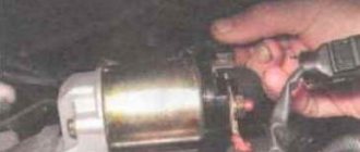
Hi all! Finally I made this damn starter! I'll tell you briefly how it all happened. After driving around, the car refused to start and I naturally went to the store to look at the price of the issue. The price shocked me - 2600 rubles! I bought it cheaper at 2112. I decided to look for a used one and found it for 800 rubles from a company called Katya, basically a famous company for basins, it’s like luzar pumps, only with a starter!), and so I bought it. So I came to the garage, started installing it, while I was tightening the wires on the solenoid relay, I broke the partition, some kind of spring flew out, well, I wasn’t at a loss and decided to start it, check, maybe to hell with it) my brother stood watching, I started it... I heard a cry: “ GOOD, THERE IS A SPARK HERE.” ummm. I went to get a new retractor - I paid 500 rubles, I was happy, I thought that was it! go! I turned the key once, twice, three times, and it started. But the Bendix (gear on the starter) spun at idle and did not engage the flywheel. There was a lot of swearing, sadness, but nothing. I went home in my faithful friend Chrysler) I looked on the Internet, corresponded with Tokha and decided to change the Bendix. (350r) starter analysis:
1. Unscrew the bolt securing the wire connecting to the starter. 2. unscrew the 2 bolts (which hold the solenoid relays
4. Unscrew the 2 long bolts from the butt of the starter. and take out the “front part with bendix”, be careful, you can pull the lower part and your brushes will fall out, but we don’t want that!
5. put the rotor aside and take the front part 6. We knock off the washer on the retaining ring, by the way the retaining ring is not even visible because of this crap 7. Well, we pick out the retaining ring, I almost lost my fingers!)))))
8. We take everything out and go to the store to pick it up)
9. Reassemble everything in reverse order. In the end, I spent 1,700. I had to get a new one!)))) Today we also had time to mock on the track, and in the swamp) as always, everything is fine, but apparently I tore off my pants, now the TAZ is screaming like a cool guy, but it’s not moving! :DDD I also fixed the electrics, now everything works like a charm) and I’m slowly dismantling the interior) I decided that I’ll leave part of the torpedo, and make part of it from aluminum, and instead of the standard buttons, I’ll put a toggle switch. I’ll also soon make a snorkel, and then raise it), everything is ready for the rear suspension... but the muzzle is waiting for its time) By the way, we should bring the material for the bumpers in the near future) Okay, good luck to everyone, bye!)
Source
Lada Oka Younoo › Logbook › Starter disassembly sequence Kherson (Oka)
Maybe someone will find this useful
(without photo)
1. Using a 13mm wrench, unscrew the nut of the lower contact bolt. 2. Remove the wire tip. 3. Holding the nuts with an “8” wrench, unscrew the screws securing the traction relay to the front roof. 4. Remove the traction relay and spring. 5. Having lifted, we take out the anchor. 6. Having installed the starter 391.3708 vertically, hit the open-end wrench “14” with a hammer and press the restrictive ring. 7. Using a screwdriver, pry up the locking ring and remove it and the restrictive ring. 8. Using the “8” wrench, unscrew the two coupling bolts. 9. Remove the coupling bolts. 10. Remove the back cover and take out the rubber gasket. 11. Remove the four brush springs. 12. Separate the front cover and the housing. 13. Remove the drive with the overrunning clutch. 14. To replace the drive lever, unscrew the lever axis and remove it. 15. Remove the drive lever. 16. Use a screwdriver to pry up the lock washer and remove it 17. Under the lock washer there is a package of adjusting washers 18. Remove the rotor from the starter 19. Use a screwdriver to pry up the back cover and remove it from the body, while two brushes come out of the guides 20. Two brushes connected to stator windings can be disconnected by unsoldering the connection. 21. To replace the other two brushes, use a slotted screwdriver to unscrew two screws and remove the brushes and brush guide.
We assemble the starter in the reverse order of disassembly. the armature shaft splines and the rear cover bushing with engine oil.
.
the drive ring of the drive with Litol-24 lubricant
.
When assembling the connection of the housing with the front and rear covers, seal it with sealant
.
When installing the back cover on the case, we align the recess of the cover with the protrusion of the case.
When installing the front cover on the case, we also align the recess of the cover with the protrusion of the case.
When installing the restrictive ring onto the locking ring, it is convenient to tighten it using sliding pliers
.
When installing the traction relay on the front cover, seal the connection with sealant
.
Before turning on for the first time, it is advisable to check the assembled starter for short circuits.
.
Under the lock washer there is a pack of adjusting washers.
Source
Models, characteristics, location
The designers did not borrow a starter from other VAZ models, but made a new one - for Oka engines. The impossibility of unifying starters for owners of this small car often results in problems, since the “native” starter is not a particularly reliable unit.
It is noteworthy that Oka’s power electric motors were produced by several manufacturers. The most common is the unit with the factory index 39.3708 (KZATE Samara plant), which we will consider in the future. Also, the VAZ-1111 was equipped with Belarusian-made components (1111-3708010-5) and Slovenian ones - AZE-1517.
The main characteristics of model 39.3708 are as follows:
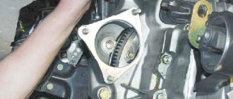
This unit is mounted on the left side of the engine (in the direction of travel) above the gearbox, and the thermostat housing is located above it. Fixation is carried out with only two fasteners - a bolt and a nut, with which the starter is attracted to the clutch housing. This arrangement is convenient because you can dismantle the unit from the car without removing anything additional.
Selecting components: how to choose a starter
The design of the starter for the VAZ 1111 is completely different from other AvtoVAZ models - the company's engineers have completely redesigned the design of the device to reduce the size and weight of the part. It was this step that subsequently became a problem for many car owners: the fact is that the stock version of the starter is not particularly reliable, and the commonality of the parts prevents the quick selection of an alternative replacement model.
The original starter kit for the VAZ 1111 has a mass of about 3.5 kg and produces a power of 0.9 kW with a current consumption of 230 A. The part is installed in the direction of movement of the engine on the left side above the gearbox structure, and the device is fixed using two fastening bolts that attract element to the clutch housing. This design solution is very advantageous in that it does not require disassembling other car engine systems to repair or replace components.
| Manufacturer | vendor code | Voltage, V | Device weight, kg | Approximate cost, rub. |
| ZiT | 7102.34548-01 | 12 | 3,65 | 2750 |
| ZiT | 7102.3708-01 | 12 | 2.80 | 3200 |
| ZiT | 1111-3708010 | 12 | 2.90 | 3300 |
| ZiT | 7102.3708000-01 | 12 | 3.40 | 3350 |
| AvtoVAZ | 704361 | 12 | 3.75 | 3350 |
| AvtoVAZ | 343523 | 12 | 3.65 | 3500 |
| AvtoVAZ | 030050 | 12 | 4.05 | 3550 |
Note! It is recommended to select a starter for the VAZ 1111 strictly after checking the part for compatibility with the vehicle’s VIN number - otherwise there is a risk of purchasing a part that will function unstably or lead to costly repairs to the engine or electrical systems of the vehicle.
This is interesting: Mitsubishi Lancer 10 wheels: standard sizes, bolt pattern, offset
Design
The starter on the Oka is a commutator electric DC motor. Its main components are:
All elements are assembled into a single structure and secured with coupling bolts.
The stator due to the passage of electrical energy through its windings, ensures the emergence of an electromagnetic field. The second magnetic field is created by the armature winding. Electric current is supplied to it through graphite brushes to the commutator, to the plates of which the ends of the armature winding are soldered. The magnetic fields generated around the windings lead to the rotational movement of the armature.
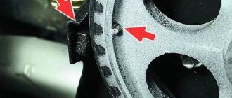
On one side of the armature shaft there are splines on which a bendix is mounted, consisting of a gear and an overrunning clutch. Bendix has the ability to move along the shaft, and due to the spline connection, rotation is transmitted to it.
The Bendix gear is designed to engage with the crankshaft flywheel and transmit rotational motion to it. By default, the gear is not engaged with the flywheel and there is no interaction between the engine and the power electric motor.
The task of the overrunning clutch is to interrupt the transmission of rotation after starting the power unit. Even at minimum speeds, the rotation speed of the crankshaft is higher than the starter speed, so after starting the engine, reverse rotation is transmitted - from the flywheel to the electric motor. engine (until the gear is disengaged), which significantly reduces the service life of the starter. To prevent this negative effect, the gear interacts with the armature shaft not directly, but through a roller clutch, consisting of two cages and rollers placed between them.
The essence of the clutch is this: while the rotation speed of the starter armature is higher than that of the flywheel (the engine is not running), the rollers “jam” the cages among themselves, thereby transmitting rotation to the gear. As soon as the engine starts and the flywheel accelerates, one of the races moves relative to the second and the rollers “wedging” occurs, due to which the transmission of rotation from the gear to the armature is interrupted.
The movement of the bendix along the shaft splines is carried out by a retractor relay installed on the starter housing. This unit is also “responsible” for supplying electricity to the electric motor windings.
The peculiarity of the starter is that the gear is first engaged, and only after that the electric motor is turned on. And all this is provided by the retractor relay.
Solenoid relay - located on the starter
The relay consists of a housing with windings located inside, a contact disk and power contacts (“nickels”), as well as an armature that engages with a fork that interacts with the bendix.
Connection diagram. Principle of operation
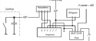
The starter is powered from the on-board network as follows: a large cross-section wire is laid from the “positive” terminal of the battery to one of the contacts of the solenoid relay. From the second contact of the relay there is a bus to the brush holder and stator windings. This circuit is the main one for powering the electric motor, but there is a break in the relay, which prevents the constant supply of current to the windings.
From the same “positive” terminal there is another wire, passing through the additional relay, the ignition switch and leading to the solenoid relay. The task of this circuit is to power the relay windings.
To turn on the starter, the driver must set the key in the lock to position “2”. Thus, it closes the power circuit of the solenoid relay, and current flows to its windings. As a result, a magnetic field arises, which leads to the movement of the relay armature - it is “pulled” into the housing.
Moving inside the body, the anchor pulls the fork along with it, and it moves the Bendix along the splines of the armature shaft, engaging the gear with the flywheel.
At the same time, the anchor pushes the rod on which the contact disk is fixed. Having reached the stop, this disk is pressed against the “nickels” of the power contacts, as a result of which the electrical power supply circuit is closed. engine, and it begins to rotate, and the gear will already be engaged.
After starting the Oka motor, the clutch is activated, preventing reverse rotation.
By returning the key to position “1”, the driver opens the relay power circuit, the return spring “pushes” the armature. Moving back, it stops acting on the rod of the contact disk, due to which the electrical power supply circuit is opened. engine. At the same time, the anchor pushes the fork, and it disengages the bendix.
Main malfunctions and why the starter does not turn?
Malfunctions of the Oka starter, as well as the power electric motors of cars, are divided into two categories - mechanical and electrical. The first includes:
The most common mechanical failure is wear of the support bushings, which subsequently becomes the cause of other breakdowns. Due to significant wear of the bushings, the position of the armature and, accordingly, the bendix are disrupted. As a result, it is more difficult for the gear to engage, the wear rate of the teeth increases, and they may crumble.
Electrical faults include:
To this category of breakdowns you can also add problems with the power circuits of the electric motor and relay.
Malfunctions of the Oka starter manifest themselves in different ways:
If such signs occur, the unit should be repaired.
Diagnostics
Determining the location of the breakdown in the circuit is an important and first stage of repair. This is done like this:
- Put the car on the parking brake, turn on neutral speed;
- open the hood;
- Use a screwdriver with an insulated handle to close the power contacts of the solenoid relay.
If the starter then begins to rotate normally, the traction relay is faulty or there is an open circuit in the power supply. And on the contrary, if the device does not work or the rotation amplitude is low, the starting unit will have to be dismantled, disassembled and sorted out.
Unit dismantling, disassembly
Removing the starter on an Oka is not a difficult operation due to its relatively convenient location. The work algorithm is as follows:
Next, the unit is disassembled and diagnosed.
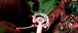
First, the retractor relay housing is dismantled, for which you need to unscrew two nuts. When dismantling the housing, the relay armature will remain in place, since it is hooked onto the fork with an eye. If necessary, we also remove the anchor.
To disassemble the electric motor itself, unscrew the two coupling bolts, after which you will be able to remove the back cover and pull the brush holder off the commutator. After this, you can remove the stator housing with the winding.
For further disassembly, remove the retaining ring from the front of the armature shaft and pull out the armature. All that remains is to pull out the fork axle and remove it along with the bendix.
Mechanical faults can be identified visually by carefully inspecting each component part. If signs of severe wear or damage are detected, the part should be replaced.
As for electrical faults, they can only be identified by testing the windings. For such a check, it is better to contact an experienced electrician.
After repair, the starter is assembled in the reverse order. Before installing it on a car, it is advisable to check the unit. To do this, connect it directly to the battery.
8.2.8. Starter repair
- key "8"
- screwdriver
- electric soldering iron
1
- cover on the drive side
2
- drive gear
3
- armature shaft
4
- housing
5
- cover on the commutator side
6
- traction relay
1.
Unscrew the nut of the lower contact bolt of the starter traction relay.
2.
. remove the washer and disconnect the stator winding terminal tip.
3.
Remove the two starter traction relay mounting nuts (one shown).
4.
Remove the traction relay from the cover on the drive side.
5.
Remove the traction relay armature from the cover on the drive side, disengaging it from the drive lever.
6.
Remove the drive lever stop by prying it off with a screwdriver.
7.
Unscrew the two coupling bolts and...
8.
. Remove the cover from the manifold side cover.
9.
Remove the casing gasket.
10.
Remove the brush springs from the brush holder.
11.
Remove the lock washer from the starter armature shaft and.
12.
. adjusting washers.
13.
Separate the starter housing and the cover on the manifold side (if this cannot be done by hand, use a screwdriver).
14.
Remove the insulated brushes from the brush holder and.
15.
. Remove the starter cover from the manifold side.
16.
Remove the spacer washer from the armature shaft.
17.
Remove the cotter pin securing the axis of the starter drive lever and.
18.
. Remove the axle from the drive side cover.
19.
Remove the drive side cover.
20.
Remove the starter drive lever.
21.
Remove the starter armature from the housing.
22.
Slide the restrictor ring away from the retaining ring.
23.
Remove the retaining and limiting rings from the armature shaft.
24.
Remove the starter drive clutch assembly from the armature shaft.
25.
Remove the spring from the traction relay.
26.
To replace the brushes, remove the insulating bracket.
27.
. Use a soldering iron to heat the junction of the insulated brushes with the stator terminal and, using a screwdriver, open the bend of the stator terminal.
28.
. remove the insulated brushes.
29.
Unscrew the screws securing the ends of the non-insulated brush bars and remove the brushes from the cover on the commutator side.
Defective starter parts
30. Check the condition of the stator winding. To do this, turn on the test lamp (designed for a voltage of 220 V) into an alternating current network with a voltage of 220 V and connect one wire to one of the terminals of the stator winding, and short the other to the housing. If the lamp is on, the winding insulation is damaged. Replace winding or stator. Also check the other stator winding
When testing with 220V voltage, be careful. Do not touch live parts of the stator with your hands.
31.
Inspect the surfaces of the armature shaft under the bearings. If you find yellow deposits from the bearings on the armature shaft, remove it with fine sandpaper. There should be no damage on the surface of the shaft splines (burrs, nicks, chipping of teeth and visible signs of wear).
32.
Check the reliability of soldering of the armature winding leads to the commutator plates.
33.
The sealing gasket of the starter casing must not be damaged (ruptures, cracks, etc.).
34.
Check the starter drive by turning the gear (it should only rotate in one direction). If drive parts are severely worn or damaged, replace the drive. If you find nicks on the leading part of the teeth, grind them with a fine-grained wheel of small diameter.
35.
Check the condition of the traction relay armature spring. Replace the broken spring.
36.
The starter coupling bolts should not have severe damage to the threaded part and heads.
37.
Check the condition of the starter cover on the drive side. The presence of cracks is not allowed.
38.
Inspect the surface of the traction relay armature. Deep risks and bullying are not allowed. the anchor should move in the traction relay easily, without jamming.
39.
The starter drive lever forks must not be bent.
40.
Check the condition of the starter brushes by measuring their height. It must be at least 12 mm.
41.
Check the closure of the contact bolts of the traction relay with the plate. To do this, connect an ohmmeter to the contact bolts and press the rod of the traction relay (from the flange side). If the ohmmeter shows “infinity”, replace the traction relay.
42.
Check the condition of the inner surface of the traction relay. Risks, bullies, etc. not allowed.
Starter assembly
Assemble the starter in the reverse order of disassembly, taking into account the following features.
43.
Clean the surface of the starter armature commutator.
44.
Lubricate the splined part of the armature shaft with engine oil.
45.
. bearing-sleeve cover on the collector side and.
46.
. starter drive sliding surface.
47.
Press in the restrictive ring after installing the retaining ring on the armature shaft.
48.
Lubricate the drive ring of the starter drive with Litol-24 grease.
Copyright 2007-2019 All rights reserved. All trademarks are property of their respective owners.
Starter for OKU: what cars is it suitable for?
One of the significant disadvantages of the Oka starter is the absence of the so-called “dome”. In those nodes where it is present, the “dome” acts as a second reference point for the anchor. In Oka, due to the absence of this component, the second support for the shaft is a recess in the engine block. The support sleeve is also installed in it. Therefore, if the bushings wear out - and this is the most common malfunction - replacing them becomes a serious problem for the owner.
OKA starter catalog number: 391.3708 - if you decide to install the same one.
One of the options for solving problems with bushings is to install a starter from another car on the Oka. As a replacement, you can use the VAZ-2110 starter, which has a “dome”.
But in order to install a “ten” starter, you will have to make certain modifications to the unit itself, as well as the clutch housing, for which you will have to remove not only the starter itself from the car, but also disassemble the transmission - remove the gearbox, clutch and dismantle the clutch housing.
To install the VAZ-2110 starter on the Oka, you need to use a grinder. machine to grind the surface of the “dome”, thereby reducing its diameter. You will also have to cut the mounting lugs.
In the crankcase, you need to cut out the partition from the inside and grind the surfaces adjacent to the mounting hole.
All these modifications are aimed at ensuring that the new unit fully “fits” into the crankcase hole.
Some craftsmen, instead of the “native” starter on the Oka, even installed a unit from a VAZ of the classic family, the same VAZ-2106. But in this case, the improvements were significant, since the starter from the “classic” is larger. The installation issue in this case was resolved by using an adapter plate.
Replacement and size of bushings
Those car enthusiasts who have no desire to redo anything to eliminate armature play will have to change the bushings.
There will be no problems with the interior, since it is installed in the back cover and it is not difficult to get it out after removing and disassembling the starter. But the bushing, which is installed in a recess in the block, is difficult to get.
There are several options for extracting it:
If everything is clear with the first two methods, then the third should be considered in more detail. The method is based on the property of a liquid not to compress.
The extrusion technology is quite interesting - we select a rod whose diameter exactly matches the hole in the sleeve. Next, fill the bushing completely with grease (for example, “Solidol”). Then we insert the rod into the hole and hammer it inside. Due to compression, Solidol will penetrate under the bushing and begin to squeeze it out.
After removing the worn bushing, we install it in its place with a new one, after which all that remains is to put the starter in place.