In 1989, car enthusiasts saw the first copies of the VAZ 1111, which became the basis for the family. Three factories mastered the production of small cars: VAZ in Togliatti, KamAZ in Naberezhnye Chelny, Serpukhov, whose car plant specialized in the production of motorized wheelchairs for the disabled. This distribution of forces and resources made it possible to quickly begin production of this model without the construction of new production facilities.
Buyers were offered two versions of the car, which differed only in the power unit. The car has front-wheel drive, and replacing the Oka timing belt is carried out by analogy with VAZ 2108 and VAZ 21083 engines.
Replacing the timing belt on a VAZ 1111 Oka: diagrams and instructions
In 1989, car enthusiasts saw the first copies of the VAZ 1111, which became the basis for the family. Three factories mastered the production of small cars: VAZ in Togliatti, KamAZ in Naberezhnye Chelny, Serpukhov, whose car plant specialized in the production of motorized wheelchairs for the disabled. This distribution of forces and resources made it possible to quickly begin production of this model without the construction of new production facilities. Buyers were offered two versions of the car, which differed only in the power unit. The car has front-wheel drive, and replacing the Oka timing belt is carried out by analogy with VAZ 2108 and VAZ 21083 engines.
About the engine
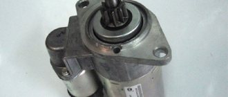
For these models, engines 2108 and 21083 were taken as the basis. They are 2-cylinder engines with an in-line vertical arrangement of cylinders. The camshaft is installed in the cylinder head. The working volume is 649 cm 3 and 749 cm 3. The increase in volume is obtained by increasing the diameter of the pistons from 76 mm to 82 mm. The cylinder blocks of these engines, heads, flywheels, and pulleys are different.
Many spare parts are unified with their 4-cylinder variants. The power supply system is carburetor, but with changed calibration data. In 1990, the timing belt on the power unit was replaced. If the previous product had semicircular teeth, then on the new one they began to have a trapezoidal shape with a groove at the top of the tooth. The pulleys were changed to match the tooth profile, but the belts themselves are interchangeable; you can use both new and old parts.
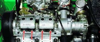
It is possible to obtain maximum efficiency from using an internal combustion engine only with the correct adjustment of the valve timing. There are marks on the timing drive for this purpose. One of them is the protrusion on the rear cover for the drive belt protection, which should coincide with the mark on the camshaft pulley. The second mark is located at the bottom of the cylinder block, and it coincides with the mark on the crankshaft pulley. The piston of the first cylinder should be at top dead center at this time.
Are the valves bending?
This question worries many owners, since after such an “incident” a costly overhaul of the power unit will follow. Mechanics know of cases where, after the pistons met the valves, in addition to bent valves, the piston heads were damaged and the guide bushings in the cylinder head were destroyed. The engine, based on the VAZ 21083 engine, is free from such shortcomings. The pistons of this internal combustion engine have recesses that prevent the valve head from meeting the upward-moving piston.
This problem can occur in two cases:
To avoid this, you should carefully study the process of replacing the belt, or seek help from service center specialists.
Which timing belt to choose
| Brand, model | Original code | Code analogue |
| Renault timing belt | ||
| Timing belt Logan | 7701477024 130C17480R 130C10178R | K015662XS 130C17529R |
| Timing belt Logan 2 | 130C17480R 130C10178R | K015662XS 130C17529R |
| Timing belt Largus | 130C17480R 130C10178R | K015662XS 130C17529R |
| Timing belt Duster | 130C11551R 7701477028 130C13130R 130C10178R | 130C17529R |
| Timing belt Renault Clio | 7701469776 7701472726 130C10178R | 130C17529R |
| Timing belt Sandero | 130C17480R 130C10178R | K015662XS 130C17529R |
| Timing belt Sandero 2 | 130C17480R | K015662XS |
| Timing belt Sandero Stepway | 130C10178R | 130C17529R |
| Timing belt Sandero Stepway 2 | 130C10178R | 130C17529R |
| Timing belt Symbol | 7701477024 | |
| Timing belt Megan | 7701469776 7701472726 130C10178R | 130C17529R |
| Timing belt Megan 2 | 130284231R 7701063999 130C13130R 130C13191R | CT977 |
| Timing belt Megan 3 | 130C13191R 7701477028 | |
| Ford timing belt | ||
| Timing belt Focus 2 | 1672144 | VKMA04226 |
| Timing belt Focus 3 | 2045356 | KTB764 CT881K5 VKMA04226 530049510 KD452.24 |
| Fusion Timing Belt | 1672144 1672143 | |
| Daewoo timing belt | ||
| Timing belt Nexia | 1987948226 530 0332 10 5900270 | |
| Timing belt Opel | ||
| Timing belt Opel | 95516740 | |
| Chevrolet timing belt | ||
| Timing belt Lacetti | 93185845 93746917 | |
| Timing belt Cruz | 95516740 | |
| Hyundai timing belt | ||
| Timing belt Accent | 24312-26001 | |
| Solaris timing belt | 24321-2B200 | |
| Timing belt Elantra | 24321-2B200 | |
| Timing belt Skoda | ||
| Timing belt Octavia | 06A198119D | |
| Timing belt Fabia | K035565XS | |
| Kia timing belt | ||
| Rio timing belt | 24321-2B200 | |
| Timing belt Soul | 24321-2B200 | |
| Timing belt LED | 24321-2B200 | |
If you can’t decide where to buy a timing belt in Volgograd, Volzhsky or another city in the region, contact us, you can’t go wrong.
Pay special attention to how to set the timing marks
. We suggest taking a little more time to watch the video of replacing the timing belt on a VAZ with a 16-valve engine.
The gas distribution mechanism (GRM) of a car fills the cylinders with a new portion of fuel and is also responsible for removing exhaust gases. This process occurs in the engine cylinders using overhead valves.
The camshaft controls the operation of the valves. It is located at the very top of the valves and rotates from the crankshaft using a toothed belt, which in addition to them also drives the water pump (pump).
Oka gas distribution mechanism
If you compare old VAZ classic engines with a timing chain drive, you will notice significant differences in the design of the drive. The bulky metal chain was replaced with a timing belt. The design of the cylinder block has become shorter and lighter, since the opening for the chain in the timing drive mechanism has disappeared. The designers changed the principle of opening valves, it became simpler. If on old engines the camshaft cam pressed on the valve stem through the rocker arm, now it acts on it through the adjusting washer. The thermal gap is set on a cold engine by selecting a washer of the required thickness. Manufacturers make them in different sizes, the values of which are marked on the ends of the washer. If the driver adjusts the thermal gap independently, he will have to purchase a certain number of such washers, which is not always economically feasible.
The design of the timing mechanism drive is such that the belt drives the pump in the Oka engine cooling system. Often it is because of the breakdown of this pump that the toothed belt drive fails. Therefore, car manufacturers recommend that the belt drive and pump in the engine cooling system be replaced at the same time. When inspecting, you should pay attention to the condition of the tension roller in the timing mechanism.
Belt replacement procedure
The process of replacing a timing belt on Oka is not very difficult. If you carefully study the process before doing this, you can do it yourself. The work can be done on any level surface.
Before starting the operation, install wheel chocks under the rear wheels and tighten the hand brake cable. The front wheels are turned to the right as far as possible (all the way), and the battery is disconnected. The further procedure will be something like this:
Features of the timing device
The same applies to the gas distribution mechanism. The essence of the work is identical, as is the design, but the VAZ Oka has 11113 switchgear. the shaft has only 4 cams. Therefore, the maintenance of the power plant of a small car is no different from the VAZ-2108.
The Oka uses a gas distribution mechanism with an overhead camshaft, which is installed in the engine cylinder head. This made it possible to abandon a number of components (bars, rocker arms). In this design, the camshafts. shafts act on the valves through pushers. In this case, it is necessary to have a thermal gap between the component elements (cam-pushrod-valve heel), which compensates for the change in geometric parameters occurring due to expansion of the metal as a result of heating.
But during engine operation, wear occurs on the surfaces of the cams, pushers and heels as a result of friction, which causes the thermal gap to change. Moreover, it is not necessary that it will increase; it also happens that the gap decreases. This often happens due to low-quality oil, which leads to the appearance of deposits on the working surfaces of the timing belt.
As a result of a change in the thermal gap, a violation of the valve timing occurs, which is why the power plant loses power (which the Oka already has “sparsely”), fuel consumption increases, and dynamics decrease. And all because the valves either open insufficiently (increased clearance) or do not fit tightly to the seats (reduced clearance).
To compensate for changes in the thermal gap, the VAZ-1111 uses special adjusting washers, which are placed in a special seat in the pusher. That is, the contact of the camshaft cam occurs not with the pusher, but with the installed washer.
In order for the thermal gap to meet the standard, periodic adjustment of the valves on the Oka is required. Due to the design features of the timing belt, the entire process boils down to installing washers of the required thickness.
Replacement timing
The vehicle operation regulations recommend that owners check the condition of the belt drive and belt tension after a run of 30 thousand km (more often). It is recommended to replace it after 60 thousand km. If the car owner does not change the belt within this period, it may be destroyed.
It is not allowed to operate the Oka with traces of engine oil leaks in the area where the toothed belt operates. It has a bad effect on the belt material and accelerates its destruction. Engine oil leaks should be repaired and the toothed belt replaced with a new spare part. If you carry out maintenance work on the power unit in a timely manner and with high quality, then there will be no problems for the owner.
Source
VAZ 11113
For ease of operation, remove the windshield washer reservoir, ignition coil and air filter housing (see the relevant sections).
Further assembly is carried out in the reverse order of disassembly.
The piston of the 1st cylinder is set to the TDC position (top dead center) of the compression stroke so that when carrying out work related to removing the camshaft drive belt, the valve timing is not disturbed. If the valve timing is incorrect, the engine will not operate normally.
Set TDC according to the mark on the camshaft pulley (when installing according to the marks on the flywheel or crankshaft pulley, the piston of either the 1st or 4th cylinder may be in this position). After this, be sure to make sure that the marks on the flywheel or on the crankshaft toothed pulley match (if the generator drive pulley has been removed). If the mark on the flywheel or crankshaft pulley does not match, it means that the valve timing is incorrect (the piston of the 1st cylinder is not installed at TDC). In this case, it is necessary to remove the camshaft drive belt and rotate the crankshaft until the marks align.
You will need: a 10" wrench, a wrench for the wheel nuts.
Location of TDC marks
TDC marks are located on the camshaft timing belt pulley (protrusion) and on the rear camshaft drive belt cover (tendril).
. on the generator drive pulley (notch), on the front cover of the camshaft drive belt (long protruding mark). The alternator drive belt has been removed for clarity. The short mark located nearby is a mark for setting the ignition timing.
Duplicate marks are placed on the flywheel - risk; on the scale of the crankshaft rear oil seal holder there is a middle cutout (the rubber window plug in the clutch housing is removed).
. there is a hole on the crankshaft toothed pulley; There is a triangular cutout on the oil pump cover. The last two marks are visible only when the generator drive pulley is removed.
1. Use a wheel wrench to turn the crankshaft by the generator drive pulley bolt through the hole in the right wheel well so that.
Rotate the crankshaft only clockwise (in the direction of rotation of the crankshaft) by the bolt securing the generator drive pulley to it. Do not turn the crankshaft by the camshaft pulley.
To make it easier to turn the shaft, you can remove the spark plugs.
Since it is inconvenient to rotate the crankshaft by the bolt securing the pulley to it, you can do this in the following ways:
1. Engage any gear (preferably 4th) and slowly roll the car until the mark on the camshaft pulley matches the mark on the rear cover of the camshaft drive belt.
2. Engage any gear and lift one of the front wheels. Then turn the suspended wheel until the mark on the camshaft pulley matches the mark on the rear cover of the camshaft drive belt.
3. Remove the three bolts securing the front camshaft drive belt cover (do not lose the flat washers).
4. Remove the front cover.
5. Check the alignment of the marks on the camshaft pulley and the rear cover of the camshaft drive belt.
6. If the mark on the pulley is on the opposite side of the mark on the rear cover, then the piston of the second cylinder is at TDC. Rotate the crankshaft one revolution.
Source
Sequencing
All work is performed on a cold engine. The whole process is done like this:
Remove the air filter housing from the car. Cover the carburetor with a rag;
We disconnect the pipes from the valve cover and move them to the side;
Unscrew the nuts securing the valve cover and remove it;
We set the TDC. To do this, rotate the crankshaft until the marks on the generator drive pulley and the timing belt cover align (since there are two marks on the cover, you need to install it on the long one);
The order of adjustment of the cylinders on the Oka is not important, since in the engine of this car they run synchronously. That is, start adjusting on any cylinder
It is only important to remember that the outer valves are exhaust, and the inner ones are inlet (exhaust-inlet-inlet-exhaust). This is necessary in order not to confuse the thermal gaps
For example, we will consider a cylinder located closer to the camshaft gear;
We measure the gaps on the valves of the selected cylinder using feeler gauges and write them down;
The pushers have special slots for removing the washer. Use a screwdriver to turn the pusher to turn one of the slots towards you;
We install a squeezing tool on the valve cover studs and secure it with nuts;
We place the handle opposite the first valve, place the lever between the camshaft. shaft and pusher, press the handle, overcoming the force of the spring;
Install the retainer between the distributors. using the pusher shaft, remove the lever and move it to the side;
Use a punch to pry up the washer, and then remove it with tweezers;
The washer has its size marked on it (if it is worn, we change its thickness with a caliper);
We calculate the required thickness of the new washer. To do this, take the thickness of the removed washer, add the measured thermal gap to the value and subtract the nominal value. Let's take the intake valve as an example. The measured gap was 0.28 mm. We removed the washer, measured it and got a value of 3.80 mm. We combine these indicators - 4.08 mm. We subtract the nominal gap (0.2 mm) from it and it turns out that you need to install a washer 3.88 mm thick. Since there is no element with this value in the set, we select the closest one to it (for this we need an error of 0.05 mm). As a result, to restore the thermal gap, a washer with a thickness of 3.90 mm is needed.
We install the selected washer and move on to the next cylinder valve. We calculate the thickness in the same way, but taking into account the fact that the exhaust valve has a nominal gap of 0.35 mm;
After making adjustments on one cylinder, move on to the other. But to do this, it is tedious to rotate the crankshaft 360 degrees. And then all work is performed in the same way as indicated above;
After adjustment, we install the removed elements from the engine, and the valve cover gasket must be replaced;
Finally, we note that this operation is also carried out in the case of work related to the removal of the camshaft, for example, when replacing valve seals.
Article on the topic - Adjusting the valves of the VAZ "Classic"
Replacing the timing belt on a VAZ 1111 Oka: diagrams and instructions
In 1989, car enthusiasts saw the first copies of the VAZ 1111, which became the basis for the family. Three factories mastered the production of small cars: VAZ in Togliatti, KamAZ in Naberezhnye Chelny, Serpukhov, whose car plant specialized in the production of motorized wheelchairs for the disabled. This distribution of forces and resources made it possible to quickly begin production of this model without the construction of new production facilities.
Buyers were offered two versions of the car, which differed only in the power unit. The car has front-wheel drive, and replacing the Oka timing belt is carried out by analogy with VAZ 2108 and VAZ 21083 engines.
When should adjustment be made?
The valve clearance on the Oka, according to the manufacturer’s recommendations, should be adjusted every 30 thousand km. But this is far from an accurate indicator, since much depends on operating conditions. Thus, lubricants, fuel, climatic conditions, features and intensity of use of the car can significantly affect the operation of the timing belt, and work on adjusting the thermal gap will have to be carried out earlier.
There are a number of signs indicating a change in the thermal gap:
Some note that fuel consumption also increases. This is true, but the Oka uses a carburetor power system (except for the latest models equipped with a Chinese 3-cylinder unit), so it is simply unrealistic to determine the amount of fuel consumed, and such a sign of a change in the thermal gap can be ignored.
This type of maintenance can be done with your own hands, since the whole process is not complicated, but you need to know how to properly adjust the valves on the Oka.
The main thing you need to know is what valve clearance on the Oka is considered normal. Here it all depends on what kind of valve it is: for the intake valve it is 0.2 mm (an error of 0.05 mm is allowed), and for the exhaust valve it is 0.35 mm (the same error).
Pushers
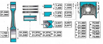
Valve pushers 12 are designed to transmit force from the camshaft cams to the valves. The pushers are made in the form of cylindrical cups with a diameter of 35.275...35.295 mm and are placed in the guide sockets of the cylinder head with a gap of 0.025...0.070 mm. An adjusting washer 11 of a certain thickness is placed in the end recess of the pusher, providing the necessary clearance between the camshaft cam and the pusher with the washer. Washers 11 are made of 20X steel and subjected to nitrocarburization, which ensures their surface hardness of 58 units on the Rockwell C scale (58 HRCe).
When the engine is running, due to the displacement of the contact zone with the cams by 1 mm relative to the axis, the pushers rotate around their axes, which ensures uniform wear along the outer diameter.
OKA car gas distribution mechanism
Maximum engine efficiency can be achieved only by correctly adjusting the valve timing. This is largely facilitated by the timing marks marked on the drive. The first of them, in the form of a protrusion, is located on the cover of the drive belt protective cover. It should coincide completely with the one located on the crankshaft pulley. The second mark is located at the bottom of the cylinder block and must also coincide with the mark on the crankshaft. When setting the marks, the cylinder piston must be at the top point (TDC).
If you compare old VAZ model engines that have a chain timing drive, which is bulky and noisy, it is not difficult to notice very significant differences. The bulky chain is replaced by a timing belt. The design of the block has changed a lot; it has become shorter and lighter. The opening of the valves has also changed, the principle has become simpler.
Structurally, the drive is designed so that it operates a pump that pumps engine coolant. Often, due to damage to the pump, the belt breaks, so designers recommend that when changing the timing belt, if possible, also replace the cooling system pump. This will avoid many further problems. You also need to inspect the tension roller; you may have to change it too.
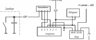
OKA ignition system
Ignition system of Oka, VAZ 2109.
How to set the ignition on Oka
If Oka's car does not start the first time, then you need to set the ignition correctly. Also, the proper functioning of the ignition affects fuel consumption and the overall dynamics of the vehicle.
First, remove the air filter. You only need to check the ignition timing when the engine is idling. The crankshaft rotation speed should be 820–900 rpm. The advance angle should not deviate more than 1° from top dead center.
Other announcements on the topic:
The ignition system is one of the main systems of a car. If the ignition timing is set incorrectly, the engine will begin to overheat, will not develop full power, fuel consumption will increase significantly, and detonation will appear. To check the ignition timing, you can
Read
Correct setting of the ignition timing in a contactless ignition system makes it possible to operate the car in comfortable conditions. Otherwise, the engine does not develop full power and fuel consumption increases. You can set the contactless ignition not only to 100, but
The normal operation of a car engine depends on the correct ignition timing. Otherwise, fuel consumption increases, the vehicle's thrust decreases, and pistons, connecting rods and piston pins are destroyed. You should inspect its installation from time to time in order to always be
https://youtube.com/watch?v=jXTcxsl8ON0
Troit Oka
.
Setting the ignition on the Oka
.
Oka
carburetor .
https://youtube.com/watch?v=Kcomcxmgf3g
We set the timing marks
In this video
I'll tell you in detail how to
set
the timing marks on
the eye
. If anyone wants to help develop the channel, here's a qiwi.
The operation of a car engine is impossible without correctly set ignition timing. This is noticeable not only when starting it with the starter, but also when driving. Increased discomfort is created from uneven operation, a drop in engine power, increased fuel consumption and, most importantly, the car
The car's ignition system is one of the main ones. Without it, there is no way to start the engine and start driving. In addition, incorrectly set ignition timing not only causes discomfort when driving a car, but also contributes to increased fuel consumption, and in some cases
Read
Ignition problems quite often occur on VAZ cars. That is why experienced motorists have developed several methods with which you can quickly and easily adjust the ignition of a VAZ. Since adjustment can take a long time, quite often it is only done
Perhaps, one of the ways to most accurately determine for yourself the correctness of the ignition timing set in a car engine is to determine the specified parameter using a strobe light, which is always available for sale in any store that sells vehicles.
The ignition timing in a car is determined by the angle of rotation of the crankshaft from the moment the spark appears at the spark plug to the position of the piston at top dead center. The ignition angle is lost due to a poorly tensioned chain or a twisted belt. For good engine operation it is necessary to set the angle
For reliable operation of the Buran snowmobile engine in difficult operating conditions, it is necessary to correctly adjust the ignition system. The most important parameter that has to be taken into account when adjusting is the ignition timing setting. As a rule, even the factory setting
>
About the engine
For these models, engines 2108 and 21083 were taken as the basis. They are 2-cylinder engines with an in-line vertical arrangement of cylinders. The camshaft is installed in the cylinder head. The working volume is 649 cm 3 and 749 cm 3. The increase in volume is obtained by increasing the diameter of the pistons from 76 mm to 82 mm. The cylinder blocks of these engines, heads, flywheels, and pulleys are different.
Many spare parts are unified with their 4-cylinder variants. The power supply system is carburetor, but with changed calibration data. In 1990, the timing belt on the power unit was replaced. If the previous product had semicircular teeth, then on the new one they began to have a trapezoidal shape with a groove at the top of the tooth. The pulleys were changed to match the tooth profile, but the belts themselves are interchangeable; you can use both new and old parts.
It is possible to obtain maximum efficiency from using an internal combustion engine only with the correct adjustment of the valve timing. There are marks on the timing drive for this purpose. One of them is the protrusion on the rear cover for the drive belt protection, which should coincide with the mark on the camshaft pulley. The second mark is located at the bottom of the cylinder block, and it coincides with the mark on the crankshaft pulley. The piston of the first cylinder should be at top dead center at this time.
Are the valves bending?
This question worries many owners, since after such an “incident” a costly overhaul of the power unit will follow. Mechanics know of cases where, after the pistons met the valves, in addition to bent valves, the piston heads were damaged and the guide bushings in the cylinder head were destroyed. The engine, based on the VAZ 21083 engine, is free from such shortcomings. The pistons of this internal combustion engine have recesses that prevent the valve head from meeting the upward-moving piston.
Camshaft
Camshaft 9, cast from cast iron, has three support journals with a diameter of 24.931...24.915 mm, which rotate in their seats. There are 24 camshaft bearings in the cylinder head and 8 camshaft bearings. Holes for camshaft supports with a diameter of 25,000...25,025 mm are processed in the cylinder head assembled with the camshaft bearing housing, which ensures high accuracy, the correct geometric shape of the holes and their alignment. There is an eccentric 10 on the camshaft that drives the fuel pump. The rear end of the camshaft has a groove for connection to the spark timing sensor of the engine ignition system.
The camshaft is held against axial movements by a thrust shaft collar located between the end of the rear shaft support and the housing of the auxiliary units. A gap of 0.15...0.53 mm between the thrust shoulder of the shaft in the rear bearing seat and the end of the seating belt of the auxiliary units housing, determined by the difference in the thickness of the shoulder and the depth of the groove in the rear support, covered by the housing, ensures free rotation of the shaft.
To increase wear resistance, the working surfaces of the eccentric cams and the surface of the camshaft journal under the oil seal are bleached. The depth of the bleached layer is at least 0.2 mm. The hardness of the cams and eccentric is at least 50 units on the Rockwell “C” scale (HRC>50).
Timing for replacing timing belt
According to the regulations, car owners are recommended to check the condition of the timing belt, as well as its tension, every 30 thousand km. It is recommended to replace the belt, despite its condition, after a mileage of 60-70 thousand km. If you do not change the belt in time, it may break, and this, as mentioned earlier, threatens very serious damage to the engine, and therefore expensive repairs.
It is strictly prohibited to operate an OKA vehicle if even the slightest traces of oil are found on the surface of the timing belt. The leak must be identified and repaired immediately, and the belt must be replaced. If the timing mechanism is serviced on time and efficiently, then the car owner should not have any problems. If you follow all the tips given in this article, replacing the belt will seem like the simplest action possible.
Will the valves bend?
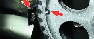
This question is sometimes almost the main one. Some motorists refuse to buy a car if the valves on the engine bend when the belt breaks. This is understandable, since after this you have to completely repair the cylinder head. And this pleasure is not very cheap. It must be said right away that on engines based on 21083, the valves do not bend. There are recesses at the top of the pistons that prevent them from hitting the valves (arrows point to them in the photo).
But on the 2108 motor there is a bending problem and it can arise in the following cases:
To prevent breakage, you need to change the belt correctly. Any motorist who knows how to handle wrenches can replace the timing belt on the Oka.
How to replace the belt on the Oka?
Difficulties should not arise when replacing the timing belt on the Oka if the procedure was always carried out in a timely and correct manner. All repair work must be carried out on a flat surface. First, place wheel chocks under the rear wheels to prevent the car from rolling.
Next you need to perform the following manipulations:
- Remove the spare tire and washer water tank from the engine compartment. You will also need to remove the air filter housing and the ignition coil.
- Loosen the tension on the alternator belt and remove it.
- Remove the plastic casing that covers the drive.
- Rotate the crankshaft clockwise to align all marks.
- Install the socket 19 through the hole on the right mudguard onto the crankshaft pulley bolt. To unscrew it, you need to secure the engine from turning. To do this, put an assistant in the car, he must press the brake pedal with 4th and 5th speed engaged.
Difficulties should not arise when replacing the timing belt on the Oka if the procedure was always carried out in a timely and correct manner. All repair work must be carried out on a flat surface. First, place wheel chocks under the rear wheels to prevent the car from rolling.
What will you need?
The only problem with timing belt adjustment is the shims. The fact is that a professional set of them is quite expensive, since it includes washers with a thickness of 3.0 to 4.5 mm (in increments of only 0.05 mm).
But many auto stores sell these washers separately, so the price of one washer is low. Only in the process of carrying out the work will you have to make all the necessary calculations, go to the auto store, purchase the required sized elements and download the assembly.
In addition, you will also need special devices - a tool for squeezing the valve and retainer. Since this specialized tool is practically not found on Oka, you can buy a regular one - for the VAZ-2108, and modify it a little.
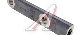
The squeeze tool consists of a tube with holes for attaching to the valve cover studs, and a handle with a curved lever (pointed at the end) connected through an axle, allowing the lever to move freely.
The tool works simply: a handle with a lever is put on the tube. It is then secured to the valve cover studs. The handle moves freely along the tube, allowing it to be positioned exactly opposite the cam. The lever is installed between the cam and the pusher; when you press the handle, it compresses the valve spring, and all that remains is to install a clamp to hold the pusher in the depressed position. You can see how everything happens in the photo below.
As for modifying the tool from the VAZ-2108 to work with the VAZ-11113, you just need to drill two through holes in the tube, the distance between which corresponds to the position of the valve cover studs of the Oka engine (it is 17.8 cm).
In general, to make the adjustment you will need:
Guide bushings
The guide bushings of the inlet 20 and exhaust 21 valves are made of cast iron, pressed into the head with an interference fit of 0.063...0.108 mm and are held against possible loss by retaining rings 23. The holes in the bushings are finally machined together with the cylinder head, which ensures a small tolerance on the diameter of the hole and the accuracy of its location in relation to the working chamfers of the seat and valve.
The holes in the guide bushings have spiral grooves for lubrication. The 20 intake valve bushings have grooves cut to half the length of the bore, and the 21 exhaust valve bushings have grooves cut along the entire length of the bore.
The outer diameter of the bushings is 14.040...14.058 mm, the inner diameter is 8.022...8.040 mm for the intake valve bushing and 8.029...8.047 for the exhaust valve bushing.
Oil deflector caps 13 made of fluorine rubber with a steel reinforcing ring are placed on top of the guide bushings, which cover the valve stem and serve to reduce the penetration of oil into the combustion chamber through the gaps between the guide bushing and the valve stem.
The site is temporarily suspended
If you are the owner of this resource, then to resume the operation of the site you need to renew the hosting service.
If the suspension of the site is caused by a violation of the terms of the Subscription Service Agreement, then to resume work you need to contact the Support Service. We will be happy to help you!
Disconnect the wire from the “–” terminal of the battery. Setting the piston of the first cylinder to the top dead center (TDC) position of the compression stroke is necessary so that when carrying out work related to removing the camshaft drive belt, the valve timing is not disturbed. Set TDC according to the marks on the camshaft timing pulley. When installed according to the marks on the flywheel, generator drive pulley or crankshaft toothed pulley, the piston of the 1st or 2nd cylinder may be in this position. Then be sure to make sure that the marks on the flywheel, or the generator drive pulley, or on the crankshaft sprocket (if the generator drive pulley is removed) match. If the marks on the flywheel or crankshaft pulley do not match, it means that the valve timing is incorrect (the piston of the 1st cylinder is not installed at TDC). In this case, it is necessary to remove the camshaft drive belt and rotate the crankshaft until the marks align.
Source
Springs
Springs (outer 16 and inner 17) press the valve to the seat and do not allow the valve pusher to come off the actuator. The lower ends of the springs rest on the support washer 18 springs. The upper support plate 15 of the valve springs is held on the valve stem by two valve nuts 14, which when folded have the shape of a truncated cone. The cotters have three internal flanges that fit into the corresponding recesses on the valve stems. This design provides both a reliable connection and the ability to rotate the valves during operation, so they wear more evenly.