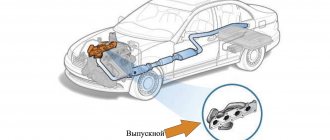
The intake manifold is a component of an internal combustion engine that is responsible for supplying the air-fuel mixture to the cylinders. Similar units are found on all types of internal combustion engines.
The intake manifold is not just pipes through which the air-fuel mixture is supplied, it has a special shape, cross-section, length, and volume. The whole point is that the mixture of fuel and air must flow evenly into all cylinders of the engine in all operating modes.
Modern intake manifolds are high-tech products that ensure stable engine operation, increasing its performance. The final power and dynamics of your car depend on the design of the intake manifold.
Operating principle of the intake manifold
During the downward movement of the pistons, a vacuum effect is formed: the flow of the mixture in the manifold rests against the closed intake valve at the stroke of the engine. As the speed increases, the mixture in the intake manifold is reflected from obstacles and begins to make “oscillatory movements.” After the formation of such movements, the flow of the mixture moves at a higher speed. Under certain conditions, such oscillations become resonant, as a result of which the mixture enters the cylinders with high pressure (the process is called resonant charging).
A properly designed manifold ensures better ventilation of the cylinders. This occurs due to the pressure difference in the intake and exhaust tracts. Valves for the intake and exhaust of gases have a certain advance step of the engine stroke. It is necessary that the valve be maximally open or closed at the optimal moment, that is, during one cycle of cylinder operation, both valves are slightly open for a fraction of a second. The pressure at the inlet becomes slightly higher than at the outlet (where gases have already been released). This ensures more efficient purging of the combustion chamber.
Requirements for the composition of the fuel-air mixture
The combined operation of the throttle and intake valves of a modern injection engine with a direct injection system provides several types of mixture formation. Different mixture compositions are necessary for engine operation in different modes.
Layer-by-layer mixture formation is necessary for engine operation at low speeds. In this case, the throttle valve is fully open most of the time, and the intake valve is closed.
Homogeneous (uniform) mixture formation is used for high engine speeds. In this case, the degree of opening of the throttle valve directly depends on the required engine torque. The intake flaps are in the open position.
There is also such a mixture formation (lean homogeneous), in which the engine operates at medium speeds. In this case, the flap also opens depending on the torque, and the intake flaps are closed.
Types of intake manifolds
There are the following types of intake manifolds:
- steel;
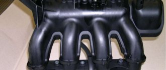
- aluminum;
- plastic;
- with variable geometry;
- with exhaust gas control valves (EGR);
- turbocharged;
- with point fuel injection, etc.
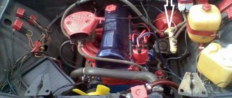
On modern engines, manifolds with point fuel injection are quite common. In this modification, fuel is supplied using electromagnetic injectors installed in each of its pipe-channels.
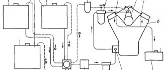
Schematic diagram of an intake manifold with point fuel injection
The intake manifold, like the engine as a whole, operates productively within a certain speed range. The design and type of installed manifold depends on the layout of the cylinder block, on the target orientation of the engine and on design solutions in general.
All of the above collectors are divided into two groups:
- single-plane;
- two-plane.
A single-plane manifold supplies the air-fuel mixture through one common channel, while a multi-plane manifold initially divides the mixture flow into two streams.
Single plane manifold
Typically, engines with dual-plane manifolds produce more power at low and mid-range speeds between 2000-4000 rpm. At high levels, the power will be slightly lower due to the turbulence formed.
Dual-plane manifold
A manifold with a common chamber without partitions reveals its potential at speeds of 5000 and above.
Installing an intake manifold of a different modification does not guarantee improved engine performance. Usually such parts are designed together with it.
What is it for?
So, as you can see, without a high-quality intake system consisting of a different number of sensors and actuators, it is impossible to create an economical, but at the same time quite dynamic and environmentally friendly car.
The only drawback of modern intake systems is the high cost and complexity of maintenance. If a carburetor engine can be diagnosed and repaired by the efforts of an experienced auto mechanic, then the electronics are checked only on special equipment. To repair it, you need to visit a specialized service center.
As a supplement, we suggest watching a video lecture about the car’s intake system:
ICE Theory: Intake Systems
Variable geometry intake manifolds
The system for changing the geometry of the intake manifold deserves special attention.
Engines with variable intake tract length
Pulsing movements in the intake manifold certainly helps its operation, but the process only starts within a range of certain vibration frequencies. The pulse length is proportional to the length of the collector pipe. This principle is used in variable-length intake manifolds. The electronic engine control unit controls the speed and sends a signal to the valve to turn on the “small” or “large” mixture supply circle.
Design of collectors with changing channel cross-sections
If the cross-section of the intake manifold changes along the direction of movement of the fuel mixture, dampers are installed, which in the closed position do not completely block the flow of the mixture, but reduce the clearance of the manifold. A change in the flow cross-section leads to turbulence and an increase in its speed. Such devices are controlled by an on-board computer.
An example of the implementation of a manifold with a variable cross-section for diesel and gasoline engines
Intake manifolds with exhaust gas recirculation system
Intake manifolds with EGR Exhaust Gas Recirculation systems are designed to reduce toxic emissions into the atmosphere. Similar manifold designs are installed on both gasoline and diesel engines. The principle of operation is simple - exhaust gases from the exhaust system flow back into the intake manifold through a separate valve, which reduces the oxygen content in the air-fuel mixture, which means the intensity of oxidation and the temperature in the combustion chambers are reduced. The system turns on only in certain modes, for example, at idle.
How to increase air supply to the engine: available methods
As you can see, the power of the power unit will directly depend on the quantity and quality of air entering the cylinders. In order to obtain improved performance from the internal combustion engine, many car enthusiasts seek to increase the air supply to the unit. As a rule, such a need arises during the process of engine tuning, after any modifications, etc.
Next, we will look at several possible methods that do not involve fundamental alterations (for example, modifying the cylinder head channels, replacing the turbine with a more efficient one, etc.)
- The simplest and most cost-effective solution is to install a zero-resistance filter (nulevik). Although the overall increase in power from such a solution is small, on sports and specially prepared cars, installing a zero gear in combination with other improvements to the wave is justified.
However, this cannot be said about civilian cars with a “stock” internal combustion engine. In this case, the result is more harm than good, since zero-resistance filters get dirty faster and clean the air worse, which can affect the service life of the motor. In this case, no increase in power is actually observed.
- Another way to supply more air to the engine is to modify the elements of the factory system. We are talking about the air intake, pipes, and the top cover of the air filter housing.
At the very beginning, it is necessary to measure the air resistance at the inlet and after leaving the filter housing, after which work is carried out in order to reduce such resistance.
- It should also be noted that sometimes on specialized forums you can find information about an electric intake fan (dynamic fan, air swirler, dynamic charging system, electric turbocharger, etc.). At one time, manufacturers Kamann, Simota and a number of others stood out on the market.
In short, the so-called electric intake turbine allows you to supply cooled air into the intake manifold without any significant modifications, which is especially important for atmospheric engines. As a result, cooled rather than warm air begins to flow into the engine, the volume of air increases, etc.
The device is a pipe in which the impeller is installed. During operation, the impeller rotates, creating spiral-like vortices of air. According to manufacturers, this air is colder and penetrates better into the combustion chambers.
As a result, the overall process of mixture formation improves, engine power increases, elasticity increases when the internal combustion engine operates in different modes, and the car demonstrates improved dynamic characteristics.
However, as practice shows, there is no particular benefit after installing such solutions. Moreover, the high cost is around 300-400 USD. and completely casts doubt on the feasibility of such experiments.
- Also on the list of possible solutions for increasing air supply is the so-called “cold intake”. Such a solution actually involves moving the air intake from the engine compartment to the outside, which makes it possible to reduce the temperature of the incoming air and increase its density.
We also recommend reading the article about what a turbocharger is. From this article you will learn about the design of the turbine, the principles of turbocharging, as well as the features of this system, the advantages and disadvantages of this solution, etc.
There are ready-made kits on sale for both specific car models and universal ones. The advantages of cold intake include increased engine power, reduced risk of detonation, improved reactions to pressing the gas pedal, and a slight reduction in fuel consumption.
This significantly increases the likelihood of water getting into the intake and water hammer, and the air filter gets dirty much faster. The fact is that the air intake is placed in “windows”, which are made separately in the bumper, in the headlight, etc.
Repair and maintenance of intake manifolds
A modern intake manifold is a complex part. Breakdowns also happen to it. Let's look at typical ones.
Leakage problems
This is the first problem with intake systems, as well as many other components of the car. Vibrations, changes in humidity, pressure and temperature affect rubber (paranitic, etc.) seals, of which there are quite a few in complex intake systems. Additional air may enter the mixture, the so-called “suction”.
Additional portions of oxygen deplete the mixture, the engine loses traction, and problems with idle speed appear. There may be engine ECU errors. All these symptoms indicate problems with the tightness of the intake tract.
Air leaks in the intake manifold can significantly affect the dynamic performance of the engine as a whole. After the seal is restored, engine operation returns to normal.
Gaskets for intake and exhaust manifolds of VAZ 2106
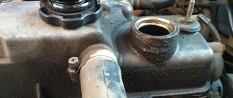
Intake manifold contamination
The intake tract must be checked from time to time for deposits on the walls. A problem like this can have a significant impact on the dynamics of the car. The manifold becomes clogged especially often on engines with an exhaust gas recirculation system. In such cases, it is necessary to disassemble and clean the device with a special compound.
Deposits on the walls of the intake manifold elements
Deformations and mechanical damage to the housing
Plastic and aluminum are widely used for the production of collectors, and these materials, as is known, can be deformed due to exposure to high temperatures. Plastic cracks and dries out over time. Aluminum manifolds may burst due to vibrations. Elements with severely damaged geometry must be replaced. Aluminum parts can be welded using argon arc welding.
Increased air temperature in the intake manifold
The causes of this problem may be:
- long-term idling in conditions of high air temperature (for example, in traffic jams);
- malfunctions of the cooling system and an increase in the overall engine temperature;
- poor ventilation of the engine compartment due to a clogged radiator;
- erroneous reading of the temperature sensor in the intake manifold;
- errors in the control unit firmware.
The solution is to check the cooling system components and diagnose electronic systems.
Design
The intake system includes the following elements:
- Air intake. Each car model has its own design. The key element in this unit is the air filter. It is placed in a housing (often it is a tray hermetically sealed on all sides, but there are also open filters installed directly on the air intake), which has an open pipe on one side. Through this hole, the air enters the filter element, is cleaned and enters the intake system pipe. Air filters are discussed in detail Here.
- Throttle. In the modern version, this is an electrically driven valve that is installed on a pipe running from the air intake to the manifold. Depending on the needs and loads of the motor, the electronic control unit issues the appropriate command to open/close the damper. This controls the internal air flow.
- Receiver (or collector). An intake manifold is installed between the throttle and the cylinder head. This is a pipe of complex design. On one side it has one, and on the other, several pipes (their number depends on the number of cylinders in the block). The purpose of this part is to distribute the internal air flow among the cylinders. If the fuel system is of a distributed type, then a hole will be made on each pipe in which a fuel injector will be fixed. In this case, the intake system is directly involved in the formation of the air-fuel mixture. If the engine has direct injection (the injectors are located near the spark plugs or glow plugs in diesel engines), then the intake simply regulates the air supply.
- Intake flaps. These are additional valves that are installed inside the manifold pipes to regulate the type of mixture formation. These elements are used in internal combustion engines with direct injection.
- Air sensors. They record the strength of the air flow in front of and behind the damper, as well as its temperature. Signals from these sensors are sent to the control unit.
The ECU is responsible for the synchronous operation of all actuators of the intake system. Based on signals received from the gas pedal, mass flow sensor and other sensors equipped with the vehicle, the electronics activates a specific algorithm. In accordance with the “brain” program, all devices simultaneously receive appropriate signals.
Local ventilation of premises
Local exhaust eliminates exhaust air in places where it is polluted. The set of industrial hoods includes exhaust fans, pipelines, and ventilation grilles.
Local ventilation, designed to remove substances belonging to hazard classes 1 and 2 from the equipment, is arranged so that when the ventilation system is turned off, starting the equipment becomes impossible.
In some cases, backup fans are provided and local exhaust systems are equipped with automation. Such ventilation is divided into 2 types - supply and exhaust. The supply type of ventilation is performed in the form of thermal curtains and air showers.
Thermal curtains from the air
Openings that remain open for a long time (more than 40 m per shift) or open quite often (more than 5 times) contribute to hypothermia of people in the room. The operation of drying plants that emit pollution also leads to negative consequences.
In these cases, air curtains are installed. They act as a barrier against cold or very overheated air.
Air and air-thermal screens are designed so that in cold weather, when the openings are opened, the temperature in the workshops does not drop below the mark:
- 14°C - while performing work that does not require much physical effort;
- 12°C - when the work is classified as moderate;
- 8°C - when doing heavy work.
If workplaces are located close to gates and technological openings, screens or partitions are installed. The air-thermal curtain near doors facing outside should consist of air with a maximum temperature of 50°C, and at the gate - no more than 70°C.
Local exhaust using special suction
The local exhaust system, using special suction, first captures and then removes harmful impurities in the form of gases, smoke and dust.
This is a kind of air shower, the task of which is to pump fresh air into a fixed place and lower the temperature in the inflow area. It is used in production, where workers are exposed to high temperatures and radiant energy with an intensity of more than 300 kcal/m² per hour, emitted by heating and melting furnaces.
There are such installations both stationary and mobile. They must provide a blowing speed from 1 to 3.5 m/s.
The use of an air shower is one of the ways to establish a thermal balance between a person and the environment in which he is forced to be.
There is also such a thing as an air oasis, which is the same device included in the local ventilation system. It creates a microclimate with specified parameters in a certain part of the production room.
Purified air supplied to a given exclusion zone is usually subjected to special heat and humidity treatment.
An air oasis creates improved conditions in the workplace and neutralizes exposure to harmful substances. Often these are separate cabins, but when their installation is not possible, a stream of air is directed to the workplaces
If the local suction device is brought directly to the place of release of substances polluting the space, it will be possible to remove air containing a higher percentage of them than with general-exchange ventilation. Local ventilation can significantly reduce air exchange.
Air exchange calculation
If no harmful substances are released as a result of production activities, then the amount of air required for ventilation is calculated using the formula:
L = N x Lн , where
N is the number of people usually in the room, Lн is the volume of air required for 1 person, measured in mᶾ/h. According to the norm, this is from 20 to 60 mᶾ/h.
Using a parameter such as air exchange rate, the calculation is performed using the formula:
L = n x S x H , where
n is the air exchange rate in the room (for a production room n=2), S is the area of the room in m², and H is its height in m.