Combining safety and convenience. Varieties of control methods
The advantages and benefits of remote locking systems are now known even to the inexperienced car owner.
Although there are still many cars that are not equipped with such systems, their popularity has affected even the most conservative driver. You should see it once and try it - there will be no more questions.
The most persistent of drivers deciding whether to install this system, and those who want to have maximum convenience at a minimum cost, can be recommended to install electric locks only on the front (most frequently used) doors. The amenities are almost the same, but the level of security is lower due to the fact that the owner may still sometimes forget to lock the rear doors manually.
The combination of vehicle safety and user convenience will be most complete when the remote locking system is “linked” to the car alarm. This will provide the following benefits:
- the level of vehicle security increases, since simultaneously with the remote activation of the security mode, all doors are automatically locked;
- the reliability of vehicle protection increases, since after the driver exits the vehicle, automatic door locking can be activated (passive activation with door locking);
- The personal safety of the driver and passengers increases when the doors are locked when the ignition is turned on.
The information material below not only introduces an almost complete set of connection diagram options, but, most importantly, in our opinion, helps solve the three main problems that arise when implementing any remote locking system:
- determine what type of central locking is installed on the car;
- “match” the central locking with the car alarm;
- connect door lock control buttons.
GENERAL INFORMATION
The main elements of remote locking systems are door lock drives (actuators) and controllers - special control devices.
The most common door lock drives are electric drives, which we will consider in more detail.
Special control devices, often called central locking controllers, usually installed by the car manufacturer, provide simultaneous unlocking and locking of all car doors (possibly, at first, only the driver's door) using a central button or a regular car key. (We will also include some elements built into the car alarm and used to remotely control the locks as a central locking controller).
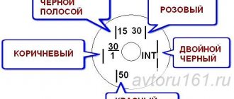
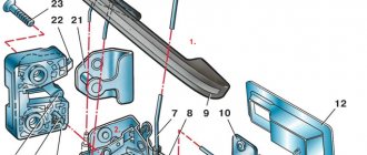
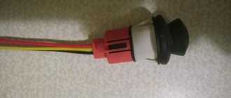
During installation, special attention should be paid to the method of connecting the buttons (either newly installed or already installed in the car). The given diagrams of two types of buttons can help solve this problem. When one side of the double button is pressed, only one moving contact switches to the position indicated by the dotted line.
The second moving contact remains in its original position and will switch to the dotted position when the second side of the button is pressed.
When one side of the single button is pressed, the moving contact switches to the dotted position and, when released, returns to its original position.
Electric door lock drives (actuators)
Electric drives (electric motors) for door locks are available in several design options, differing in the value of traction force (from 2.5 to 6 kg).
All of them use DC electric motors and plastic (or metal) gearboxes built into a plastic housing, converting rotational motion into linear motion. The direction of translational movement of the motor output rod is changed by reversing the polarity of the supply voltage, which is how the door lock is unlocked or locked. The most common electric motors are T-shaped (“pistol”) and square types.
The electric motors of the locks are controlled by a pulse voltage lasting 1 s. Electric motors differ in the presence or absence of a contact microswitch, mechanically connected to a retractable rod. The three wires of this microswitch are led out and, together with the two supply wires of the engine itself, form the so-called five-wire “master motor”, usually installed in the front doors. The microswitch built into them, together with the control unit, ensures that the rear door electric drives are activated when the front door lock is manually unlocked/locked using a regular car door key or door button.
A type of lock is a “master lock”, which has a locking mechanism that prevents the lock from being unlocked using the door button (lever). This type of lock can only be unlocked electrically.
A complete door motor kit includes 2 5-wire master motors, 2 or more 2-wire conventional motors (without switch), and a control controller (module).
A type of electric lock drive has appeared, which has an electromechanical fixation of the output rod in a locked state, preventing the thief from opening the door using any mechanical device. The normal opening of such a lock is carried out by two successive impulses (the so-called “two-stage unlocking”). This type of unlocking is provided in the central locking controllers built into car alarm systems for both Top Line (Cel, Ireland) and Internet (Internet Auto Security, USA) systems.
Typical characteristics
Traction force, kg - 2.5-3.5; Stroke of the output rod, mm - 19; Force for manual unlocking/locking, kg - 0.25-0.14; Current consumption, A - 2-3; Control pulse duration, s - 0.7-1.5; Dimensions, mm - 134x60x30.
Central locking controllers
Purpose and types of controllers
Central locking controllers provide:
- automatic door locking when the car alarm is armed;
- automatic unlocking of door locks when the vehicle is disarmed.
Additional functions of the central locking controller can perform:
- locking/unlocking the rear door lock when locking/unlocking the front door with a car key or door lever (button);
- locking/unlocking door locks when turning the ignition on/off.
The controllers are interfaced with electric lock drives directly or through microswitches of electric door drives. Car manufacturers produce a number of cars with central locks (controllers) installed on them. The most universal controllers provide the setting of different locking and unlocking times. The main task for obtaining automatic control of door locks when installing a car alarm is the selection of the appropriate car alarm, as well as the correct way to connect it to the central locking of the car (if it is already installed).
It is necessary to distinguish between three types of car alarms with built-in central locking functions according to the capabilities they provide for controlling door locks.
First view. Car alarm with built-in full-featured central locking controller.
Such a built-in controller has two powerful relays (each with switching contacts) with a permissible current load of 10-20 A. To ensure automatic unlocking/locking of the rear door lock when opening (locking) the front door with a car key or lever (button), as a rule, two negative synchronizing inputs for connection to the “master electric drive” (Fig. 1). The total number of lock wires is 8. The car alarms SIRIO 777, CLIPPER 80/4, 80/6, MICROCAR ALARM 052. 1, SERPI STAR GR-44, SERPI STAR GR-440 and others have a fully functional controller.
Second view. Car alarms with built-in central locking have the same functions as the first type, but they do not have synchronizing inputs. The total number of lock wires is 6. This type of central lock is available in car alarms PYTHON System 80, Puranha PRM 18, Clifford XL100, Flash Point 600, Enforcer 600, Mongoose, Mega 3000, Ungo.
Third type. This type of car alarm controller has an electronic circuit with low-power outputs with a permissible current load of 200-300 mA, sufficient to connect to them, if necessary, standard relays or car central locking inputs. The number of outputs is 2. The outputs, in most cases, have negative signal polarity, but there are also bipolar ones. Low-power locking controller outputs are provided in car alarms VIPER Code Plus, Enforcer 100A5, 200A5, 300V, FORCE 7002 and others.
Standalone lock controllers
Autonomous lock controllers include devices that are interfaced with car alarms and perform the functions of a central lock. Such controllers have two main versions:
- with one control input;
- with two control inputs.
Controller with one control input
Converts the negative output of the car alarm blocking into pulse signals from the contacts of two powerful relays, one of which occurs at the moment the security mode is turned on, and the other at the moment it is disarmed. These pulses provide control of the lock motors.
The controller often has additional negative clock inputs connected to the "master" motor. This controller is used with car alarms that do not have standard outputs for central locking.
The M3 controller, which has both potential and pulse outputs, is produced by Spal, and the MC 2050 controller is produced by Autotecnica.
Controller with two control inputs
The controller is used to convert two pulsed low-power control signals into pulsed high-power relay signals. Essentially contains two standard relays with switching contacts, the windings of which are connected to the control inputs. Used to increase the power of central locking outputs for car alarms of the third type, discussed above. Controllers of this type are produced by many companies (for example, the M4 controller from Spal).
Typical characteristics
Pulse duration
- — for electric drive control: 0.7 — 7 s.;
- — for “vacuum”) control: 3.5 — 6 s.;
- — for “comfort” type control (closing windows and sunroof) — 30 s.
Current load - 15 A. Current consumption - 10 mA.
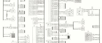
Options for central locking connection diagrams
There are seven main options for central locking connection diagrams. These options are formed depending on the polarity of control signals and the type of switches (buttons) of the central locking system. For ease of use with any type of car alarm, the diagrams of these options have, where necessary, contact designations for standard car relays. All electric drives are usually connected in parallel to each other. The only exceptions are systems that have the ability to initially unlock only the driver's door.
Selection of car alarms and connection diagrams
When choosing a door lock control option, the following sequence is recommended:
- Determine the type and polarity of control of the central lock installed on the car;
- Determine the type and polarity of the central locking switch (button);
- Determine whether a lock motor is installed in the driver's door;
- Choose the most suitable type of car alarm: with a full-featured central locking controller, with a central locking without synchronizing inputs or with low-power outputs for the central locking;
- Select the appropriate connection diagram from the options presented or modify it for your specific application.
Let's point out two simple options that may be useful.
A. The car does not have central locking. It is recommended to choose a car alarm with a built-in central locking controller that has powerful outputs from relay contacts.
B. The car is equipped with a central locking system with negative control, but it is required to control it from the car alarm. We recommend choosing a car alarm with low-power negative outputs for the central locking.
How the device works
The car's central locking can be activated both when the ignition is running and when the ignition is turned off.
As soon as the car owner locks the car doors by turning the key, a microswitch in the lock is activated, providing locking. It transmits the signal to the door control unit, and then further to the central unit. This element of the system analyzes the received information and redirects it to the actuators of the doors, trunk and fuel flap. Subsequent unlocking follows the same pattern.
If a motorist locks the car using the remote control, the signal from it is sent to an antenna connected to the central control unit, and from there to the actuators that lock the doors. At the same time, the alarm is activated. On some vehicle models, the windows on each door may automatically roll up when the doors are locked.
If the car is involved in an accident, all doors are automatically unlocked. A signal about this is transmitted from the passive safety system to the central locking control unit. After this, the actuators open the doors.
TYPE A. Positive Control
This type of control is characterized by the positive polarity of control pulses. In Fig. 2 and 4 show diagrams for a car in which a central locking controller is already installed by the manufacturer, and pairing with the car alarm is carried out through relays built into it. In Fig. Figure 3 shows an option for pairing with a car alarm system that has low-power negative outputs that are connected to additional relays.
This type of control is typical for cars from General Motors Corp., Renault, Chrysler, VW Passat and some Ford models.
If you look at the switch installed in the driver's door that controls the locks, there will be three wires coming from it: a lock wire, an unlock wire, and a positive wire that is permanently connected to +12 V.
The unlocking and locking wires will have a potential of +12 V during locking and unlocking. When these wires are connected to a car alarm, a short-term positive potential (pulse) will appear on them.
"Children's castle" in the car
Children can behave unpredictably. If the driver carries a child in the back seat, then it is difficult to control the behavior of the small passenger. Curious kids may accidentally pull the car door handle and open it. The consequences of a small prank are unpleasant. To eliminate this possibility, a “child lock” was additionally installed on the rear doors of the cars. This small but very important device prevents the door from being opened from the inside.
An additional lock that blocks the opening of the rear doors from the passenger compartment is installed on both sides of the body and is activated manually.
The method of activation of the mechanism depends on the make and model of the car. In some cases, the locking is activated using a lever, in others - by turning the spline. But in any case, the device is located next to the main door lock. For more information on using the child lock, please refer to your vehicle's owner's manual.
“Child lock” allows you to block the opening of doors from the inside and protect small passengers from falling out of the car
TYPE B. Negative control
This is the simplest standard type of door lock control. It is used in cars from Fiat, Lanchia, Volvo, Citroen, BMW (pre-89), Toyota, Honda and others. If you look at the switch installed in the driver's door that controls the locks, there will be three wires coming from it: a locking wire, an unlocking wire, and a negative wire that is permanently connected to ground.
The unlocking and locking wires will be at ground potential while locking and unlocking the locks. When these wires are connected to a car alarm, a short-term negative ground pulse will appear on these wires.
Scheme in Fig. 5 shows the connection of the system to a car that does not have central locking and a lock drive.
Schemes in Fig. 6, 7, 8 are shown for car alarms with low-power control outputs, and Fig. 9, 10 - for powerful relay outputs built into car alarms. In Fig. 7 shows how to make a connection with protection against unlocking the rear doors by children.
Notes for Toyota vehicles: Many Toyota models have a lock control system with additional protection that prevents children from unlocking the rear doors. In this case, you need to keep in mind the following: if the door locks are locked by the car alarm command, then they can be unlocked by another command. But if the door locks are locked using the driver's door switch and the security system is turned on, then they cannot be unlocked by the car alarm command. This occurs because the security switch blocks the unlocking signal.
To make the correct connection, it is necessary to use decoupling diodes installed in the release wire circuit (Fig. 7).
The wire for this protection can be found in the common lock control wiring connector. Color chart for protection wires (the protection wire is located under the side panel trim at the driver’s feet).
| Toyota car model | Wire color |
| Camry | Blue red |
| Celica | Green |
| Cressida | Light green |
| MR-2 | Blue red |
| Sypra | White blue |
| PickUp | Red Blue |
| 4-Runner | Red Blue |
| Land Cruiser | Blue\orange |
Door lock installation procedure
Before installing an electric lock for the fifth door or a drive for swing doors for rear passengers, you need to implement this function at the front. Installation of the Ford Transit electric sliding door and rear door can wait for now. During the installation process you will need:
- an alarm device capable of sending certain impulses to specified wires;
- a pair of electric drives;
- about six meters of stranded copper wire (double);
- two rubber corrugated tubes;
- standard female-male connectors with ground crimp or a more convenient European round version.
Twist the pre-stripped ends of the wires and crimp them at the base with pliers so as to catch a little of the insulation. A good crimp should result in a reliable contact that does not require additional soldering. Then decide on the connection - there should be outputs for locks, a “male” for connecting to the car’s wiring and a “female” for ground.
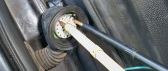
It is necessary to remove the trim from the door and slightly bend the lever with the rod from the button towards you so that the glass does not touch the electric drive lock when lowering. Cut the drive rod by about ten centimeters. In order not to make a mistake with the dimensions, it is advisable to do this directly at the installation site. Mark points for fasteners, make holes and screw the drive. Return the door button to its place and push the actuator rod as far as possible. Then fix the button and drive rods. The button should move without interference or effort.
After drilling holes in the door and pillar, thread corrugated rubber bands through them for wiring. Make sure that the cables do not break. Now you can connect power to the alarm. Often it is taken from the cigarette lighter. The ground can be taken from the metal mount of the starter. Conveniently route the cables from the alarm into the engine compartment, and also lead the wires inside the door, passing them through the rack and corrugation. Connect the female connectors to the electric drive and connect in parallel to the car circuits. Finally, install and configure the shock sensor. Now you can check the functionality of the door drive by opening and closing it using the alarm key fob.
TYPE C. Polarity reversal control
This control method is used in Chrysler, Ford, Chevy Cavalier (95-96), BMW 325 (95) cars. This type of control is often confused with 3-wire positive control. This occurs due to the fact that positive control pulses appear on the wires of both systems. The difference is that the unlocking and locking wires in this control option, in the initial state, have mass, but in option A they have an indefinite (floating) potential.
This type of control does not have factory relays installed. The control switch directly controls the electric door drives, changing the direction of the current in their winding. Therefore, when using this control circuit, it is necessary to use external relays. During installation, you must be especially careful, because incorrect connections will lead to immediate damage to system elements. As protection, it is necessary to use a 3 A fuse in the +12 V power supply circuit.
If you look at the switch installed in the driver's door that controls the locks, there will be five wires coming from it: one wire with constant +12 V power, two wires showing constant ground and two wires having ground in the initial state, and a pulsed positive potential at locking or unlocking when the switch is pressed.
Example. When the Lock switch is pressed, the lock wire will have +12 V, the second unlock wire will be in its original state and ground.
When the Unlock switch is pressed, the polarity on the second wire will be reversed to +12V and the lock wire will be ground.
It is extremely important to determine which of the two reversing wires is the unlocking wire and which is the locking wire.
Recommendations for connection.
- Cut the locking wire;
- Press both ends of the Lock and Unlock switch alternately. If you cut the correct wire, the door locks will not lock or unlock. If the door locks operate in any other direction, then you have cut the wrong wire or the system does not have polarity reversal control;
- Refer to the illustration to determine which end of the wire goes to the lock switch and which to the motor. To do this, press and hold the Lock switch (make sure it is the right side) and the end of the wire from the switch will have +12 V. Connect this end of the wire to terminal 87A of the lock relay. The other end of the wire will come from the electric motor. Connect it to terminal 30 of the locking relay.
- Cut the release wire. This wire will have +12V when the Unlock switch is pressed. Once cut, the system will also not work in any direction.
Repeat the procedure for recognizing the ends of the cut wire. Connect the end from the switch to terminal 87A of the unlocking relay and the end from the electric drive to terminal 30 of the same relay.
Installation of the VAZ-2110 lock actuator
You begin to appreciate many things after they are gone. The same applies to the additional options of the VAZ 2110. Central locking (CL), for example, you can not notice as long as it works properly or you can do without it altogether. But you quickly get used to good things, don’t you? Therefore, when something that provides us with a comfortable ride fails, you immediately begin to rush around in search of answers “how to fix it.”
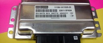
Central locking device VAZ 2110
VAZ cars are not least good for their high maintainability. Whenever something happens to your iron horse, you can almost certainly solve the problem yourself without the help of specialists at a service station. “Ten” was no exception in this regard.
TYPE D. Special positive control
This type of control is highlighted separately as it applies to cars with central locking, but without an electric drive in the driver's door. Central locking is provided by a microswitch installed in the driver's door. For remote control, the microswitch in the door is removed and a five-wire drive is installed in it. The wires from the drive microswitch are connected to the wires of the removed microswitch (Fig. 13).
Let's make the alarm system and central locking together
Any modern alarm unit is equipped with two relays connected to the central locking control unit. One relay is opening, the second is locking, and the circuit in the general case looks like this:
In our case, the green and white cords coming from the signaling unit will be required, as indicated in the diagram. However, they will not be the only ones needed. We will connect the relay contacts to breaks in the standard wiring. This means there will be not 2, but 4 cords.
Connection diagram for VAZ central locker
Take another look at the diagram published in the first chapter. We will connect the relay to the gap in the white and brown wires going from the microswitch to the central lock control unit. And it is obvious that it is easier to break these wires near the 8-pin connector. The same one shown at the beginning.
TYPE E. Vacuum control
This type of system uses a compressor to open and close the door locks. Used in Mercedes and Audi cars.
Depending on what signal the compressor receives from the lock drives, they can be push or pull type.
When using this type of system, first of all, you need to find and cut the wire that controls the compressor.
WARNING. To determine the purpose of the ends of the cut wire, you should only use a voltmeter (do not use a test lamp). It is very important to identify and not mix up the ends of the wires going to the compressor and to the lock switch (you must label them). Due to an error in determining the sides of the wire, the compressor may be damaged.
NOTE. On most Mercedes Benz vehicles, the compressor control wire will be green or blue and can be found under the side panel trim near the driver's feet. This wire will have +12V when the doors are unlocked and ground when the doors are locked.
How to choose a central locking manufacturer?
When choosing a central lock, you should take into account the country and manufacturer. Devices from China are a very affordable and budget option, however, there is a high risk that such a lock will not last long. Doubtful manufacturers even have locks or their components that are not initially suitable for your car. Therefore, before purchasing, you should carefully check the traction, fastenings, and whether the set of parts is complete. However, in recent years, Asian manufacturers have grown greatly in terms of the quality of their goods, so you may come across an excellent, reliable copy.
When choosing a central locking manufacturer, first of all take a closer look at the price - a high-quality lock should not be cheap, otherwise there is a high risk that one day the doors will simply jam - this happens quite often. It is especially dangerous to buy a lock not in a specialized store, but “from hand” and from unverified sellers. “Alligator” has also proven itself quite well.
Before deciding which lock to choose, be sure to take into account the make of your car - so that the type of fastening is suitable, the drive power is sufficient to control the locks. Most locks are quite simple and can be installed yourself if you have any knowledge of auto mechanics. The system can also be quickly and reliably installed in any car service center.
TYPE F. Single Wire Positive Control
Control is achieved by changing the level of positive potential on a single-wire line. This type of control is used on Ford Probe and Chrysler vehicles (Fig. 16, 17). This single wire provides both locking and unlocking. To ensure proper operation, both wires from the auxiliary unlock and lock relays must be connected to the same vehicle wire that controls the door locks.
Ford Probe car
The control wire is located under the panel trim at the driver's feet and is green/black. The locking signal is a +12 V positive pulse. The unlocking signal is a +12 V positive pulse connected through a 4.7 kOhm resistor.
Cars Chrysler Cirrus, Dodge Stratus 1995
Models 1993-1995 New Yorker, Concorde, LHS, Eagle Vision have this type of control or 3 wire positive control. This single wire provides both locking and unlocking. To obtain normal operation, both wires from the additional unlocking and locking relays must be connected through appropriate resistors to the same vehicle wire that controls the door locks (see Figure 17). The resistors used provide conversion of +12 V voltage from additional relays into a +3 V lock signal and +6 V unlock signal.
The locking signal is a +12 V positive pulse connected through a 620 Ohm resistor.
The unlocking signal is a +12 V positive pulse connected through a 2.7 kOhm resistor. Control wire color chart (the control wire is located under the driver's side panel trim)
| car model | Wire color | Connector |
| 1995 Chrysler Cirrus | White\light green | Brown 16 pin |
| Dodge Stratus Chrysler New Yorker, Concord, LHS, Eagle Vision, 1993-1995 | Orange\purple | Blue or black 16 pin |
Problems in the operation of the activator electric drive
The central locking actuator is quite fragile and does not tolerate overload. The activator body, made of plastic, can easily melt if the frequency of door closing is excessively high. The duration of the control pulse also plays an equally important role. Try to always remember about the extreme fragility of the activator and not to load it during operation.
It is easy to guess that the activator is located in each individual door of the car. If the body of one of them melts due to overheating of the electric drive commutator, this becomes the cause of many problems:
- the activator on individual doors stops functioning;
- Constant overloads in a jammed electric drive cause the fuse to fail.
The actuator mechanism is entirely made of plastic. Gears can easily wear out and break during operation, or melt when the commutator overheats. As a result, when the central locking operates, characteristic creaking sounds are heard - a sure sign of imminent failure of the activators. Likewise, if the gearbox of the mechanism is humming, but the doors do not open or close.
Malfunctions of this kind can also be associated with all sorts of defects in the gearmotor and its traction. If you have recently replaced your central locking system, the reason may be that it was installed incorrectly. The mechanism may also be incorrectly adjusted or the fastening may be damaged. In any case, the door trim should be removed and checked visually.
TYPE G. Single wire negative control
Cars Dodge Caravan, Chrysler Town & Country, Plymouth Voager1996 r.
This type of control uses (same as control type F) a single control wire, but with negative pulse signals at ground potential.
The locking signal is a negative ground pulse connected through a 1.5 kOhm resistor.
The unlocking signal is a negative ground pulse connected through a 249 Ohm resistor. Control wire color chart
| car model | Wire color |
| 1996 Dodge Caravan, Plymouth Voyager, Chrysler Town & Country | White\light green |
Location:
A). Connector 40-pin (5th pin), light brown, under the dashboard on the driver's side in the control module, in front of the fuse box;
B). Connector 16-pin, black. Near the fuse box or under the trim panel near the driver's feet.
Mazda car
This type of control uses negative control with a single resistor in the gate circuit. The locking signal is a negative ground pulse connected through a 1 kOhm resistor. The unlocking signal is a negative mass impulse.
Control wire color chart
Car make Mazda 929
A). The light green wire is in the black 20-pin connector in the driver's footwell panel.
or
B). Black/white in a white 6-pin connector in the passenger footwell panel.
Mazda Mellenia
A). Red/black wire in the 28-pin white connector in the driver's foot panel;
or
B). Blue/yellow wire in the 28-pin white connector in the passenger footwell panel.
Nissan cars, Mazda MPV 1991
The locking signal is an open input of the control wire, provided by a relay. The unlocking signal is a negative mass impulse.
Control wire color chart
car model
Nissan 240SX1991 -1994
Orange\blue or orange\black wire in the driver's side panel.
Nissan 300 ZX 1992-1995
Brown or brown\black wire in the driver's side panel.
Mazda MPV 1991
Green/white wire in the lock control module connector in front of the glove box.