The crankcase ventilation system plays a major role in the gas exchange process inside the engine. Its malfunctions can lead to turbine breakdown and oil loss through the seals. For timely diagnosis and detection of signs of malfunction, it is extremely important to understand the operating principle of the crankcase ventilation system. We will pay special attention to the design of the PCV valve (Positive Crankcase Ventilation) and methods for checking it.
Purpose of the crankcase ventilation system (CVG)
Crankcase ventilation is necessary to continuously remove the toxic mixture of unburned hydrocarbons, exhaust gases and oil mist. Before the tightening of environmental standards, the breather, a piece of hose connecting the engine block and the atmosphere, did an excellent job of this task.
In modern realities, crankcase ventilation is a closed system. Exhaust gases are fed into the intake manifold, where they are mixed with a fresh charge and safely burned in the engine.
Operating principle of the mechanism
As the system is currently known, the gases are not simply released into the atmosphere. They are sent to the engine through a tube removed from the crankcase, the other end of which is connected to the intake manifold. From there, the gases are directed into the combustion chamber. At the moment of a flash, some of them burn out, and the other part is thrown out through the release mechanism. Only a small fraction of these gases enters the crankcase again. This is how the process occurs without interruption.
Operating principle and design of crankcase ventilation
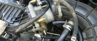
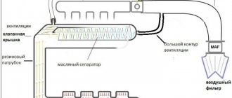
This is exactly what the crankcase ventilation diagram of an atmospheric gasoline engine looks like. Gases from the cylinder head enter the intake tract through two pipes, one of which cuts into the system before the throttle, and the second after the damper. This separation of threads is necessary for two reasons:
- At idle and low load, the throttle valve is open to a small angle. The amount of air passing through the filter and entering the throttle space is minimal, and the vacuum is greater behind the throttle. Therefore, excess crankcase gases are sucked into the intake manifold into the throttle space. The amount of gases passing through the channel is regulated by a one-way valve VKG.
- In medium and high load modes, the throttle valve is open to a large angle and does not create obstacles to the passage of air. At the same time, due to an increase in speed, not only the engine’s oxygen consumption increases, but also the amount of gases breaking into the crankcase. Since the vacuum behind and in front of the throttle will be small, both channels are used to effectively remove crankcase gases.
The diagram shows the elements of the crankcase ventilation system of a turbocharged engine, as well as the method of gases entering the sump through the piston rings (No. 5). Components:
- Oil separator. Prevents oil vapor from entering the intake manifold.
- PCV valve that meteres the amount of gases.
- Intercooler. Adding hot exhaust gases reduces the density of the fresh charge, causing engine power to drop. The cooler eliminates this negative factor.
- Turbocharger.
PCV valve
High vacuum in the crankcase space is no less dangerous for oil seals than high pressure. To prevent excessive vacuum from being created in the sump at a small opening angle of the throttle valve, as well as when the throttle is abruptly closed at high speeds, a VKG valve is included in the system. The crankcase ventilation valve consists of a spring-loaded plunger moving in a sleeve of a certain cross-section.
In normal condition, when the engine is turned off, the return springs press the plunger, connecting the channel sections from the manifold to the valve cover. At idle, high vacuum in the intake manifold attracts the plunger, overcoming the resistance of the springs. The crankcase gas access channel is blocked. As the throttle valve opens, the effect of vacuum on the plunger decreases. The force of the return springs opens the valve, connecting the intake tract and the crankcase space.
The role of the oil separator
An oil separator, often called an oil sump, is designed to capture large and fine oil particles. Its role is extremely important for the proper operation of the mass air flow sensor (MAF). As oil mist settles on the walls of the intake tract, it quickly becomes covered with dust. Because of this, the operation of the flow meter’s sensitive element is disrupted. The engine control unit receives incorrect readings about the amount of air entering the intake tract. Therefore, forced crankcase ventilation of a modern engine may include several types of oil separators.
Labyrinth oil trap
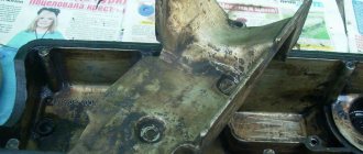
When gases move through the labyrinth, large oil particles under the influence of inertial forces are pushed towards the walls of the oil separator. The oil flows by gravity through the separator plates into the pan. An oil trap similar in operating principle, consisting of a set of plates, is installed in the valve cover of VAZ injection engines.
Cyclic oil trap
Designed to capture fine particles of oil suspension. As crankcase gases pass around the circumference of the oil separator housing, oil droplets move outward, settling on the walls of the oil separator housing.
Oil separator with filter element
Filter paper or fiberglass filler is installed inside the housing. Passing through the filter, the oil is retained on the walls of the filter element, after which it flows into the pan.
Turbulence of exhaust gas flows moving through the crankcase ventilation hose impairs the uniform filling of the cylinders. Therefore, many cars have an additional sedation chamber installed. In addition to a gas flow retarder, the chamber also acts as an additional oil separator.
Design
In modern cars, the crankcase ventilation system has a more complex design. It consists:
- Branch pipes, hose;
- Oil separator;
- valves.
Oil separator
Designed to separate oil vapors from gases. This is necessary so as not to clog the intake manifold and its elements with oil. Moreover, getting it into the cylinders during fuel combustion will not bring anything good; the quality of the fuel mixture is impaired, etc.
There are two types:
- Tangential or centrifugal type;
- Labyrinthine.
The first type has the shape of a cone or cylinder. It has two pipes at the top and one at the bottom. In the upper part of the oil separator, hoses from the engine crankcase are connected to one inlet fitting. The second outlet is the outlet; a hose is attached to it, which removes gases without oil vapors to the ventilation valve. The lower pipe drains the separated oil into the oil receiver (crankcase).
Oil separator for crankcase ventilation system, centrifugal type
Principle of operation
Crankcase gases enter the oil separator into the inlet pipe. In the housing, they are given a tangential movement; they are twisted in a spiral relative to the central axis of the separator. Due to centrifugal forces and the fact that oil is heavier than gas, the former settles on the walls of the device. Gases rise upward and move further through the system through the outlet fitting. The oil flows down, returning to the engine.
Crankcase ventilation valve
It is needed to control the supply of exhaust gases from the crankcase to the engine intake manifold. Since a large vacuum is formed there, a vacuum can be created in the engine crankcase through the pipe system. This means that even more gases will make their way into the crankcase. Plus, the probability of “sucking” fuel vapor into the crankcase increases significantly.
Crankcase ventilation valve
Principle of operation
The valve, depending on the engine load, opens when the vacuum in the manifold is low and closes when it is high. The pressure in the crankcase increases, the valve opens slightly. Gases are “sucked” into the intake, reducing pressure. If a vacuum is created, the valve closes, stopping the suction of gases from the crankcase into the intake manifold. This regulates the flow of exhaust gases through the crankcase ventilation system and maintains a slight vacuum. For more details, watch the video:
Signs of malfunction
- Excessive oil fogging in places of rubber seals. It is pointless to change the cylinder head gasket, pan or oil seals without eliminating the cause of the increased pressure of crankcase gases. The reason may be either insufficient crankcase ventilation performance or critical wear of the cylinder-piston group (hereinafter referred to as the CPG). In the latter case, more crankcase gases leak into the pan than the crankcase ventilation system can pass through. On cars with a synthetic filter element, we first recommend checking the condition of the filter.
- Excessive oil consumption. Increased pressure in the crankcase prevents the oil scraper rings from working effectively, causing oil to burn in the cylinders.
- Floating idle speed. The reason is a leak in the system. Cracks in hoses, PCV valve body, loose clamps - all these factors lead to the leakage of unaccounted air.
- Persistent smell of exhaust gases when driving at low speeds and while parked with the engine running. The closed crankcase ventilation system is leaky in the section up to the VCV valve, which is why gases break into the engine compartment, from where they are drawn inside the car by the cabin fan.
- A large amount of oil in the intake manifold, pipes and even on the air filter. The reason is a faulty oil trap.
What it is
During operation of an internal combustion engine, high pressure builds up in the chamber. Some of the exhaust gases “break through” in the gap between the piston and the cylinder wall. They get into the engine crankcase.
Many will object. The pistons have compression and oil rings that should prevent this. But gaps still exist. As the piston group wears, this distance increases. This is especially true for used cars.
In addition to the exhaust, gasoline vapors or the fuel itself can enter the crankcase if the fuel system or ignition fails. Crankcase ventilation serves to remove combustion products of the fuel-air mixture.
What is a crankcase ventilation system on an atmospheric engine?
Consequences of faulty crankcase ventilation
Consequences of high pressure in the crankcase:
- Damage to the rubber seals of the crankshaft and camshaft. The engine will lose oil through squeezed out oil seals. If a sharp decrease in level is not noticed in time, oil starvation can lead to wear of the rubbing pairs and rotation of the liners.
- Turbine failure. After lubricating and cooling the turbocharger parts, the oil should drain by gravity into the pan. If there is a backlash of gases in the crankcase space (a kind of plug), the volume of engine oil pumped through the turbine will sharply decrease. Due to deterioration of heat dissipation, the oil will begin to coke inside the channels and on hot rubbing vapors. The consequence is scuffing on the liners and turbine shaft, which is equivalent to a deep restoration or replacement of the cartridge/turbocharger assembly.
- Squeezing out the dipstick and splashing oil into the engine compartment. In some cases, the dipstick flies out with such force that it leaves a noticeable dent in the hood. In this case, you won’t be able to get rid of it just by washing the engine compartment.
Video: Crankcase ventilation system
Diagnostic methods
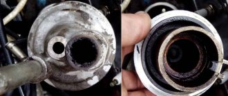
The easiest way to check the PCV valve is by yourself. To do this, just blow into the valve from the side of the valve cover. If the air pressure from the reverse side is weak or does not come out at all, the valve is not working properly. Cleaning the crankcase ventilation system with carburetor cleaner should correct the situation. If the valve is blown in both directions, most likely it is stuck in a half-open state, or the rubber membrane is torn.
The degree of contamination and the overall efficiency of the crankcase ventilation is measured in two main ways:
- The crankcase gas pressure is measured at different engine operating modes.
- The volume of gases that the system can pass through itself is measured.
In order not to encounter the consequences of malfunctions of the VKG system, it is worth periodically changing the PCV valve, filter element, and cleaning the centrifugal/labyrinth oil trap.
How to repair
In old domestic cars, the factory installed a so-called “breather” to solve the problem. It was direct-flow, constant action. You just had to monitor its frequency. Periodically disassemble the structure and wash it from oil deposits.
Engine crankcase ventilation system on domestic cars with breather
Modern cars have not come far in terms of system maintenance. It is necessary to periodically check its operation as described above. In case of problems or failures, we clean all elements. They are, in most cases, removable, can be washed with gasoline, dried and reinstalled.
The crankcase ventilation valve on many models is repairable. Let's take it apart and check why it jams. If it is “overgrown” with oil deposits, then wash it. If there is mechanical damage, we replace it.

