The exhaust manifold is the first component of a car's exhaust system. Structurally, these are several channels combined into one common channel that transmits exhaust gases further along the exhaust tract. Exhaust manifolds are installed on all types of internal combustion engines, regardless of their brand or purpose. Exhaust manifolds are necessary to collect and remove exhaust gases.
Exhaust manifold layout
A properly designed and selected manifold contributes to more efficient ventilation of the cylinders, which means more optimal filling of the air-fuel mixture. A similar effect is achieved due to the movement of exhaust waves inside the manifold channels.
Why does a car need an intake manifold?
The intake manifold has many tasks, but the main one is supplying air (lots of air).
Speaking in technical language, he is responsible for:
- Supply of air flow involved in the preparation of the fuel mixture in compliance with the ratios specified by the engineers;
- Uniform distribution of air into the cylinders;
- Use of VUT vacuum to enhance forces in the braking system;
- Operation of the crankcase ventilation system (CVG);
- Controlling the speed of the power unit at idle due to the operation of the throttle.
For each power unit, its own intake manifold is developed, the geometry of which will be optimally matched to the engine architecture.
Main signs of pollution
Thermal tape for muffler, exhaust manifold
It is recommended to periodically clean the interior surface. This is due to the fact that it is almost impossible to avoid the formation of soot on the surface; during long-term operation of the car, the collector becomes covered with a layer of soot several millimeters thick. Some signs may also indicate the need for cleaning:
- All carbon deposits that form remain inside the structure and accumulate over time, reducing throughput.
- Fuel consumption increases significantly. In order for the consumption to be within the normal range, the combustible mixture must consist of a certain amount of fuel and air. In addition, an incorrectly enriched mixture reduces the main performance indicators of the internal combustion engine.
- Power decreases and acceleration dynamics are lost. It is quite difficult to determine the drop in engine power, since it occurs gradually. Only when diagnosing a vehicle can the power rating be determined.
- At low speeds, vibration and shaking may occur. Due to a decrease in throughput, pressure increases, which leads to vibration.
- The car idles poorly and the revs drop. A situation often occurs when the engine almost completely stalls at idle. This also occurs when the fuel mixture is poorly enriched.
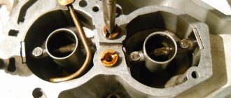
- In some cases, contaminants crystallize, break off, and end up on the valve. Contamination of the valves complicates their movement, causing strong knocking and noise. The accumulated mass on the valves complicates their movement.
Severe contamination of the intake system occurs due to high oil consumption when the cylinder-piston group is damaged. This further aggravates the current situation; the engine finally loses its quality.
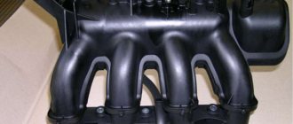
Device
Although from the outside the intake manifold appears to be just a pipeline of a specific shape, in fact a whole team of engineers works on its geometry, calculating the cross-section, length and volume.
Plus, it includes:
- Throttle valve;
- Supply chamber;
- Air filter;
- Inlet valve;
- Discharge chamber.
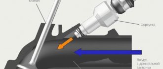
For engines with distributed fuel injection, injectors are additionally installed in the intake manifold, due to which the mixing of fuel and air masses occurs directly in the discharge chamber.
The pipeline itself can combine from 2 to 12 channels, depending on the number of cylinders in the engine block. At the same time, for a 4-cylinder engine, a manifold with three pipes is sometimes used.
It is also worth noting that most modern intake manifolds over the past 5 years have been made from special high-temperature plastic, while the exhaust manifold can still only be made from metal.
Inlet valve
Cold intake: pros and cons
The intake valve of the gas distribution mechanism allows access to the fuel-air mixture into the cylinder and stops access before the start of the compression stroke. In the case of a diesel engine, the valve allows only air into the combustion chamber.
When the timing belt breaks, the intake valves “hang” as the camshaft stops rotating. Valve plates that are open hit the surface of the cylinder
The valves are located at an angle of 30 to 45 degrees relative to the vertical axis. The intake valve plate is larger than that of the exhaust valve. The difference is due to the fact that at the moment the intake valve opens, a vacuum is formed in the combustion chamber, and at the moment of exhaust - increased pressure. The vacuum force is lower than the pressure force, so the intake requires valves with a larger head surface to ensure the passage of the required volume of the fuel-air mixture.
Principle of operation
The intake manifold is connected to the air supply system. The wide part, where the pipes are located, is attached directly to the cylinder head.
After which, through the intake system, the air masses enter the supply chamber, where the air supply temperature can reach up to 120 degrees.
Then the air passes through the filter and the intake pipe, from where it enters the discharge chamber through the throttle valves, and from there, through the intake pipes, the air masses are sent straight to the cylinders.
This is interesting: What you need to know about car wheel alignment angles
A throttle, or simply a damper, regulates the cross-section of the pipeline, thereby controlling the speed and power of the engine.
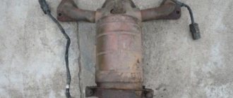
An exhaust manifold
So, the second contender, it also plays an important role - removing burnt gases. After the intake valves have been closed, the fuel is compressed and ignited by the spark plug - a mini explosion occurs, the pistons go down - the exhaust valves open and the burnt gases are removed.
It’s just that after the valves they must go into the muffler, and they are collected from each cylinder by the exhaust manifold (also one pipe per cylinder). It is also connected by its wide part to the head of the block, only (if we exaggerate) on the other side, then through the pipes the gases are collected into one large one, as a rule, first there is a catalyst that burns the gases, then after it there is a muffler (there may also be an outlet for turbine ). After this, the gases go further into the environment. It is worth mentioning that this tract extinguishes not only exhaust gases, but also the exhaust sound! More precisely, not he himself, but the muffler to which he transmits “working off”.
As you understand, the exhaust manifold operates at high temperatures, because the exhaust can often heat up to 950 degrees Celsius. Therefore, it is imperative to use metals, and not simple ones, but refractory ones capable of withstanding high levels of “heat”.
A sensor is often screwed into this outlet manifold, this is a “lamba umbrella” or an oxygen sensor; it “monitors” the content of oxygen and other gases in the exhaust.
Thanks to this sensor, the supply of the fuel mixture through our “supply” manifold is adjusted, that is, a relationship is obtained.
The exhaust tract, usually very durable in cars, lasts almost the entire life of the car.
Changing the intake manifold geometry
As already mentioned, each engine has its own intake manifold geometry. This allows you to vary the speed and improve or worsen the combustion process.
In all cases, a change in geometry results in a change in airflow speed.
As you might guess, there are only three options for changing the geometry:
- Reduce or increase the length of pipes;
- Narrow or expand the cross-section of pipes;
- Combined approach.
Since it is often not possible to “play” with long pipes, they usually choose the second option - changing the cross-section. To do this, special dampers are used that regulate air flow differently than the factory mechanism.
Premium segment cars have a combined system for changing the geometry of the intake manifold.
These are precisely those cases when the manufacturer offers different options for driving modes, such as Comfort, Dinamic, etc. The change in engine characteristics is partly influenced by the operation of the intake manifold flaps.
How does the manifold affect engine performance?
When the engine operates at maximum speed with the gas pedal fully depressed, the speed of air in the manifold approaches (and in sports cars noticeably exceeds) the speed of sound. At such speeds, any turn and the slightest bump turn out to be a serious obstacle, which greatly increases the resistance of the collector to air flow. As a result, less air enters the cylinders, so engine power drops. In this mode, the carburetor often produces an over-lean mixture, the burning rate of which is tens of times faster than normal. Therefore, the air-fuel mixture explodes, which leads to damage to valves, pistons and other engine elements.
Equally important is a high-quality connection between the manifold and the carburetor or air filter. If the sealing elements are worn out or the fastening nuts are poorly tightened, then air leaks occur at the contact point, resulting in an over-lean mixture and explosions in the combustion chamber.
Tuning
Tuning and changing geometry are two different things. When people talk about modifying the intake manifold, they usually mean increasing the incoming air volume and reducing the resistance along its path.
For this purpose the following procedures are provided:
- Replacing the air filter with a zero resistance filter. Thanks to the macroscopic holes in the latter, air is retained less and, accordingly, the speed and volume of passage increases;
- Enlargement of the throttle pipe. It also aims to increase air permeability. Usually, for this purpose, a damper is installed from another engine, which is more powerful than the original;
- Installation of a sports receiver. Short tubes with a larger cross-section, when properly configured, can reduce the pulsation of air masses, which allows the engine to gain speed faster.
There is also a tuning option when the intake manifold is completely removed and short pipes tuned to high speeds are installed instead. This option is provided only for naturally aspirated engines and is called a multi-throttle intake (that is, each cylinder essentially has its own manifold).
By the way, any changes in the intake system usually entail upgrading the exhaust manifold, camshaft and firmware of the electronic control unit.
Best answers
Timur Khatipovich:
An engine usually has two collectors, one input, the other output. through the first, fresh mixture is supplied, and through the outlet, combustion products are removed. looks like pipes diverging from one.
Father Makhno:
intake and exhaust manifold
Ivan Ivanov:
buy a book and read Yyyy COLLECTOR in technology, 1) the collector of an electric machine is a mechanical frequency converter, structurally combined with the armature (rotor) of the electric machine. Using a commutator, sliding electrical contact is achieved between the stationary part of the electrical circuit and the sections of the rotating armature winding. 2) Transistor collector (collector region) - the region of the bipolar transistor in which most of the charge carriers from its base are collected. 3) The collector of an electric vacuum device is a device (electrode, system of electrodes, etc.) used to receive or intercept the flow of electrons. 4) Drainage collector - a drainage pipe or channel that receives water from the regulatory part of the drainage network and discharges it outside the drained area. 5) Sewer collector - a section of the sewer network that collects wastewater from sewer basins. 6) An underground gallery for laying communication cables (cable collector) and for laying pipes for various purposes - water supply, gas, etc. (common collector). 7) The name of some technical devices (for example, exhaust and intake manifolds of an internal combustion engine).
Wedding photographer Salsk:
a device for removing exhaust gases from the pistons to the exhaust pipe.
valdemar:
The manifold is a part in the form of pipes located near the engine. Through one collector the combustible mixture is sucked in, and through the other collector gases are exhausted after combustion.
didje:
this thing under the car seems long
Alexander Kuzov16 Egorov:
Well, the collector is in many things, as far as I remember it is translated as volume or free space, in short, from the translation it is clear that this object is needed by its presence) but it does not do any special actions)
Malfunctions
Like any other mechanical part, the intake manifold is susceptible to failure. Given the simplicity of the design, there are not many options for malfunctions.
Basic:
- Violation of tightness. Vibrations, pressure and high temperatures destroy seals over time. Depressurization affects the quality of the fuel mixture, loss of traction and speed. The problem is solved by replacing the gaskets, after which engine operation should return to normal;
- Collector contamination. Plaque accumulates on the walls, gradually reducing the cross-section of passing air masses. Requires disassembly and cleaning of tubes, throttle and discharge chamber;
- Mechanical damage. If the collector is made of plastic, it is only a replacement. If it is made of aluminum and the damage is small, argon arc welding will help;
- Excessive temperature in the manifold. There are a lot of reasons and you need to look for them in the cooling system, clogged radiator, damaged sensor, ECU error. Also, high temperature occurs due to the banal heat outside;
- "Clap." When forming the fuel mixture, the system must be sealed. If there are disturbances in the ignition system, the gas distribution mechanism, problems in the fuel mixture formation chamber, or the tightness of the intake manifold itself is broken, you can hear those same pops. It is worth looking for reasons in all of the above places.
In the latter case, of course, it is easier to rely on the errors reported by the ECU or sign up for a comprehensive diagnostic service.
Types of manifold pipe layouts
Exhaust manifold with 4-1 layout. It consists of four pipe-channels connected into one common pipe (the number of channels corresponds to the number of cylinders).
Tubular manifold 4-1
Exhaust manifold 4-2-1. In such collectors, pipes first connect cylinders operating in pairs (on the same stroke), and then move into one common pipe.
Exhaust system 4-2-1
An important parameter of exhaust manifolds is their length, and, accordingly, their volume. If the length of the exhaust channels is insufficient, the energy of the exhaust gas flows will be enough to enter the channels of adjacent cylinders and negatively affect their operation. In such collectors, the wave movements of gases are poorly synchronized with the operation of the engine. At the same time, engines with a short exhaust manifold typically have “narrow” valve timing with a relatively small volume of exhaust gases. The production of short-length collectors is justified by low cost.
One-piece 4-1 manifold with short exhaust ports
Long exhaust manifolds are used on powerful and efficient engines. In such manifolds, part of the volume of exhaust gases flows through a common pipe into the next components of the exhaust system, and part is “reflected” to the remaining cylinders. It will take much longer for the wave to pass from one cylinder to another, which creates definitely better conditions for discharge and purging.
Exhaust kit 6-2-1
Exhaust manifold with equal length exhaust pipes (equal length). Typically installed on powerful sports cars.
Complex equal-length exhaust manifold made of pipes
An equal-length manifold allows for uniform exhaust in all cylinders and better synchronizes the operation of the engine with the exhaust system. Tuning the exhaust tract can be done on any engine. This is guaranteed to bring an additional 3-5% power.
Do not forget that increasing the length of the exhaust manifold will also entail an increase in temperature in the engine compartment.
The temperature problem is solved by installing thermal insulation. To do this, you can use a metal casing or a special non-flammable fabric.
There are models of collectors in which ceramic coating is used as thermal insulation.
Exhaust manifold cover
Collector channels insulated with special fabric
Exhaust manifold and turbine scroll with ceramic coating
DC motor design
As you know, a DC electric motor is a device that, with the help of its two main structural parts, can convert electrical energy into mechanical energy. These main details include:
- stator - the stationary/static part of the motor, which contains the field windings to which power is supplied;
- rotor is the rotating part of the engine that is responsible for mechanical rotation.
In addition to the above-mentioned main parts of the DC motor design, there are also auxiliary parts, such as:
- clamp;
- poles;
- excitation winding;
- armature winding;
- collector;
- brushes
DC Motor Design
Together, all these parts make up the complete design of a DC motor. Now let's take a closer look at the main parts of the electric motor.
The yoke of a DC motor, which is mainly made of cast iron or steel, is an integral part of the stator or static part of the motor. Its main function is to form a special protective coating for the finer internal parts of the engine, as well as to provide support for the armature winding. In addition, the yoke serves as a protective cover for the magnetic poles and field winding of the DC motor, thereby providing support for the entire field system.
The magnetic poles of a DC motor are housing parts that are bolted to the inner wall of the stator. The design of magnetic poles basically contains only two parts, namely the pole core and the pole piece, which are joined to each other under the influence of hydraulic pressure and attached to the stator.
Video: Design and assembly of a DC motor
Regardless, the two parts serve different purposes. The pole core, for example, has a small cross-sectional area and is used to hold the pole piece to the yoke, while the pole piece, having a relatively large cross-sectional area, is used to spread the magnetic flux created over the air gap between the stator and rotor to reduce magnetic loss resistance. In addition, the pole piece has many grooves for field windings, which create the field magnetic flux.