Air or a fuel-air mixture, depending on the type of engine (diesel, injection or carburetor), enters the cylinders through the intake manifold. The main purpose of the intake manifold is to ensure uniform distribution of air or working mixture between the cylinders. The efficiency of the motor directly depends on this. In addition, other components, such as a carburetor or throttle valve, can be mounted on the manifold.
The principle of its operation is quite simple: air or its mixture with fuel, entering through the inlet, is divided into several streams, according to the number of engine cylinders. The pistons, moving downwards, create a vacuum in the manifold, which can reach large values. This partial vacuum is also used to neutralize crankcase gases. They enter the intake manifold through the engine crankcase ventilation system, mix with the fuel-air mixture or air and are burned in the cylinders.
Until recently, the main materials for the manufacture of the intake manifold were aluminum, iron and cast iron. This created certain difficulties. The fact is that the collector itself gets very hot during engine operation and heats the air that is currently inside it. The air, in turn, expands and enters the cylinders in a smaller volume, as a result of which fuel consumption increases and engine performance deteriorates.
As an alternative to metal, since the late 90s, now the last century, plastic-based composite materials have been used on many cars. Due to low thermal conductivity, such an intake manifold does not heat up as much, as a result, the cylinders are better filled with air, and the engine power per unit of fuel increases.
Purpose of the intake manifold
This part is designed to ensure the supply of air and VTS to the engine cylinders while it is running. In modern power units, additional elements are installed on this part:
- Throttle valve (air valve);
- Air sensor;
- Carburetor (in carburetor modifications);
- Injectors (in injection internal combustion engines);
- A turbocharger whose impeller is driven by the exhaust manifold.
We offer a short video about the features of this element:
Intake manifold: frequently asked questions
The structure of both options
If you exaggerate, the collector is 4 pipes that connect into one. That is, a kind of “pants”, only with four “trouser legs”. It should be noted that there are also “two - three” or even “six” pipes. This device is determined by the number of cylinders in the engine, as we know on the OKA car there were only two cylinders (two pipes), for example, on the new FORD there are options with three (three pipes), and on some executive cars there are six cylinders (six pipes). Moreover, these will be both the intake and exhaust manifolds.
Here is just the top point, where one of their outputs will differ:
Intake - connects to the air or fuel supply system, so at the “top point” there will be either a carburetor or a throttle valve.
Exhaust - connects to the muffler and removes exhaust gases. Nowadays it is often connected to the catalyst.
Now in more detail about each type.
Design and design of the intake manifold
One of the most important factors affecting the efficiency of the motor is the shape of the commutator. It is presented in the form of a series of pipes connected into one pipe. An air filter is installed at the end of the pipe.
The number of taps at the other end depends on the number of cylinders in the engine. The intake manifold is connected to the gas distribution mechanism in the area of the intake valves. One of the disadvantages of the VC is the condensation of fuel on its walls. To prevent this effect of electrostatic reaction, engineers have developed a pipe shape that creates turbulence inside the pipeline. For this reason, the inside of the pipes is deliberately left rough.
The shape of the collector pipes must have specific parameters. Firstly, the path should not have sharp corners. Because of this, fuel will remain on the surface of the pipes, which will lead to clogging of the cavity and change the air supply parameters.
Secondly, the most common intake tract problem that engineers continue to struggle with is the Helmholtz effect. When the intake valve opens, air rushes into the cylinder. After its closure, the flow continues to move by inertia, and then abruptly returns. Because of this, a resistance pressure is created, which interferes with the movement of the next portion in the second pipe.
These two reasons force automobile manufacturers to develop improved manifolds that would ensure smooth operation of the intake system.
Engineering variations on the theme of reservoirs
Despite its simplicity, the exhaust manifold has varieties, the appearance of which is due to the physics of gas circulation through pipes.
Because of this, developers have to make compromises, and we will definitely talk about them. But first, the varieties.
The following types of collectors are found:
In the first case, the design turns out to be very cheap.
Its main feature is short outlet pipes and a common collection chamber. To be honest, one-piece manifolds are extremely ineffective for exhaust gas removal.
This is due to short tubes, due to which the influence of gas pulses on neighboring cylinders is great.
As a result, we have unsatisfactory purging of the combustion chambers, and this is reflected in many factors, including engine parameters.
In order for the engine to operate at maximum efficiency, tubular exhaust systems were developed.
They are the ones most often found under the hoods of modern cars.
They are exhaust pipes coming from the cylinders and converging into one (or sometimes first into several, and then into one).
When developing them, engineers have a lot to tinker with, since the engine output at different speeds depends on the length of the exhaust pipes and their diameter.
So, for example, if we take short tubes, then, thanks to the resonance effect, they will best ventilate the combustion chambers at high speeds.
But then the mutual influence of the cylinders on each other will increase.
Long exhaust pipes, in turn, are good at low speeds.
The story is similar with the diameter - a small pipe diameter is optimal from the point of view of the speed of gas removal at low and medium speeds.
But they experience a lot of resistance at high speeds, which is why the engine power drops. With larger diameter exhaust pipes the opposite is true.
Thus, engineers have to maneuver and look for compromises, which we mentioned earlier for good reason.
Principle of operation
The suction manifold operates according to a very simple scheme. When the engine starts, the air valve opens. As the piston moves to bottom dead center on the suction stroke, a vacuum is created in the cavity. As soon as the intake valve opens, a portion of air moves at high speed into the vacated cavity.
During the suction stage, different processes occur depending on the type of fuel system:
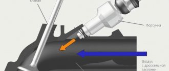
- Single injection - another portion of air comes from the filter. It passes through the carburetor or cavity in which the fuel injector is installed (if the engine is equipped with an injection vehicle). In this cavity, air is mixed with fuel. Due to the vacuum in the cylinder, this portion is sucked through the raised valve of the intake system;
- Multipoint injection - individual fuel injectors are located in each manifold pipe. When the corresponding valve opens, air is supplied through the pipe suitable to it. At the same time, fuel is atomized.
- Direct injection - only air is sucked in. The valve lowers, the piston compresses the air in the cylinder. At the end of the compression stroke, fuel under pressure is supplied through the nozzle into the compressed medium. In diesel internal combustion engines, an identical process occurs, only the air is compressed more strongly.
All modern engines are equipped with an electronic system that controls the supply of air and fuel. Thanks to this, the motor operates more stably. The dimensions of the pipes are selected to match the parameters of the motor at the stage of manufacturing the power unit.
Shape and volumetric efficiency
One of the most important parameters of the intake manifold that determines its efficiency is its shape. The basic rule that all engineers adhere to is that the intake manifold should not have any angular shapes , as this will provoke pressure drops and, as a result, worse filling of the cylinders with air or working mixture. Therefore, all collectors have smooth transitions between segments and rounded shapes.
The vast majority of current collectors use runners. They are separate pipes diverging from the central entrance of the manifold to all available intake channels in the cylinder head. Their task is to use a phenomenon called Helmholtz resonance. The operating principle of the design is as follows.
At the moment when suction occurs, air flows at a very high speed through the open inlet valve. When the valve closes, the air that did not have time to enter the cylinder retains a large impulse, which means it presses on the valve, resulting in a high-pressure zone. Then pressure equalization occurs, with lower pressure in the manifold. Due to the influence of inertial forces, leveling occurs with fluctuations: first, air enters the runner at a pressure lower than in the manifold, then at a higher one. This process occurs at the speed of sound, and before the intake valve opens again, oscillations can occur many times.
The smaller the diameter of the runner, the greater the change in pressure due to resonant air vibrations. As the piston moves down, the pressure at the outlet of the runner decreases. This low pressure pulse then travels to the manifold inlet where it turns into a high pressure pulse that travels in the opposite direction through the runner and valve, after which the valve closes.
To achieve the maximum effect from resonance, the intake valve must open at a strictly defined moment, otherwise the result will be the opposite. This is quite difficult to achieve. The gas distribution mechanism is a dynamic unit, and its operating mode is directly dependent on the crankshaft speed. The pulses are synchronized statically, the synchronization depends on the length of the runners. The problem is partially solved by selecting the length for a certain speed range at which the greatest torque is achieved. Another option is the use of systems for changing the geometry of the intake manifold and electronic timing control.
Collector pipe shape
This is a very important factor, which is given key importance when designing the intake system of a separate modification of engines. The pipes must have a specific cross-section, length and shape. Sharp corners and complex curvatures are not allowed.
Here are a few reasons why so much attention is paid to intake manifold pipes:
- Fuel may settle on the walls of the intake tract;
- During operation of the power unit, Helmholtz resonance may appear;
- In order for the system to work properly, natural physical processes are used, such as the pressure created by the air flow passing through the intake manifold.
If fuel constantly remains on the walls of the pipes, this may subsequently cause a narrowing of the intake tract, as well as its clogging, which will negatively affect the performance of the power unit.
As for the Helmholtz resonance, this is an eternal headache for designers designing modern power units. The essence of this effect is that at the moment the intake valve closes, strong pressure is created, which pushes air out of the manifold. When the intake valve opens again, the flow is opposed due to back pressure. Due to this effect, the technical characteristics of the car’s intake system are reduced, and the wear of system parts also increases.
Intake manifold geometry modification systems
Older generation cars have a standard manifold. However, it has one drawback - its effectiveness is achieved only in a limited operating mode of the engine. To expand the range, an innovative system was developed - variable collector geometry. There are two modifications - the length of the tract or its cross-section changes.
Variable length intake manifold
This modification is used in naturally aspirated engines. At lower crankshaft speeds, the intake tract should be long. This increases throttle response and torque. As soon as the speed increases, its length must be reduced in order to reveal the full potential of the car's heart.
To achieve this effect, a special valve is used that cuts off the larger manifold hose from the smaller one and vice versa. The process is regulated by natural physical law. After closing the intake valve, depending on the frequency of oscillation of the air flow (this is influenced by the number of crankshaft revolutions), pressure is created that drives the shut-off valve.
This system is used only in naturally aspirated engines, since forced air injection occurs in turbocharged units. The process in them is regulated by the electronics of the control unit.
Each manufacturer calls this system differently: BMW has it as DIVA, Ford has DSI, Mazda has VRIS.
Variable intake manifold
As for this modification, it can be used in both naturally aspirated and turbocharged engines. When the cross-section of the pipe decreases, the speed of air movement increases. In naturally aspirated systems, this creates the effect of a turbocharger, and in systems with forced air supply, the development makes the task easier for the turbocharger.
Due to the high flow rate, the air-fuel mixture is mixed more efficiently, which leads to better combustion in the cylinders.
Collectors of this type have an original structure. At the entrance to the cylinder there is more than one channel, but it is divided into two parts - one for each valve. One of the valves has a flap that is controlled by the car's electronics using a motor (or a vacuum regulator is used instead).
At low crankshaft speeds, the VTS is supplied through one hole - one valve operates. This creates a zone of turbulence, which improves the mixing of fuel with air, and at the same time its high-quality combustion.
As soon as the engine speed increases, the second channel opens. This leads to an increase in the power of the unit. As with variable length collectors, the manufacturers of this system give their name to it. Ford specifies IMRC and CMCV, Opel – Twin Port, Toyota – VIS.
For more information on how such collectors affect engine power, watch the video:
Increasing engine power without a turbine! All about the variable geometry manifold.
How does the manifold affect engine performance?
When the engine operates at maximum speed with the gas pedal fully depressed, the speed of air in the manifold approaches (and in sports cars noticeably exceeds) the speed of sound. At such speeds, any turn and the slightest bump turn out to be a serious obstacle, which greatly increases the resistance of the collector to air flow. As a result, less air enters the cylinders, so engine power drops. In this mode, the carburetor often produces an over-lean mixture, the burning rate of which is tens of times faster than normal. Therefore, the air-fuel mixture explodes, which leads to damage to valves, pistons and other engine elements.
Equally important is a high-quality connection between the manifold and the carburetor or air filter. If the sealing elements are worn out or the fastening nuts are poorly tightened, then air leaks occur at the contact point, resulting in an over-lean mixture and explosions in the combustion chamber.
Intake manifold faults
The most common malfunctions in the intake system are:
- Violation of tightness at the installation site of gaskets;
- Formation of soot and resin on the inner walls;
- The formation of a step at the junction points (a 2-mm obstacle is enough for the engine power to drop by about twenty percent, but this is only at low speeds);
- Overheating due to proximity to the exhaust manifold.
Typically, gaskets lose their properties when the engine gets too hot or when the mounting studs become loose.
Let's look at how some intake manifold malfunctions are diagnosed and how they affect engine operation.
Coolant leaks
When the driver notices that the amount of antifreeze is gradually decreasing, an unpleasant smell of burning coolant is heard while driving, and drops of fresh antifreeze constantly remain under the car, this may be a sign of a faulty intake manifold. To be more precise, not the manifold itself, but the gasket installed between its pipes and the cylinder head.
Some engines use gaskets that also ensure the tightness of the cooling jacket of the internal combustion engine. Such malfunctions cannot be ignored, because subsequently they will certainly result in a serious breakdown of the unit.
Air leak
This is another symptom of a worn intake manifold gasket. It can be diagnosed as follows. The engine starts and the air filter pipe is closed approximately 5-10 percent. If the speed does not drop, it means that the manifold is sucking in air through the gasket.
Violation of the vacuum in the engine intake system causes unstable idle speed or complete failure of the power unit to work. The only way to eliminate such a malfunction is to replace the gasket.
Less commonly, air leaks can occur due to destruction of the intake manifold pipe(s). for example, it could be a crack. A similar effect occurs when a crack forms in a vacuum hose. In this case, these parts are replaced with new ones.
Even more rarely, air leaks can occur due to deformation of the intake manifold. This part needs to be changed. In some cases, a vacuum leak through a deformed manifold is detected by a hissing sound coming from under the hood while the engine is running.
Carbon deposits
Typically, such a malfunction occurs in turbocharged units. Carbon deposits can cause the engine to lose power, misfire, and increase fuel consumption.
Another symptom of this malfunction is loss of traction. This depends on the degree of clogging of the inlet pipes. It can be eliminated by dismantling and cleaning the collector. But depending on the type of manifold, it is easier to replace it than to clean it. The reason is that in some cases the shape of the pipes does not allow carbon deposits to be properly removed.
Problems with dampers for changing intake geometry
The dampers that regulate the air supply to the manifold in some cars are powered by a vacuum regulator, while in others they are electrically driven. Regardless of what type of damper is used, the rubber elements in them deteriorate, causing the damper to no longer cope with its task.
If the damper drive is vacuum, then you can check its performance by using a manual vacuum pump. If this tool is not available, then a regular syringe will do. When a vacuum drive leak is detected, it should be replaced.
Another malfunction of the damper drive is the failure of the vacuum control solenoids (solenoid valves). In engines equipped with an intake manifold with variable geometry, a breakdown of the valve that regulates the change in the geometry of the tract may occur. For example, it may become deformed or it may stick due to carbon buildup. In the event of such a malfunction, the entire collector must be replaced.
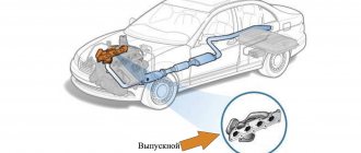
Exhaust system
The exhaust system is necessary to remove exhaust gases and reduce noise during their exhaust. Consists of an exhaust manifold and an exhaust pipe. In modern engines, to improve environmental performance, a catalytic converter is additionally installed between the exhaust manifold and the exhaust pipe.
Figure 4.43 Exhaust system.
An exhaust manifold
The exhaust manifold (schematically shown in Figure 4.43) is a part installed directly on the cylinder head and designed to redirect exhaust gases further into the exhaust pipe.
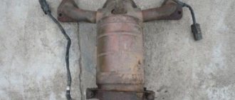
This element of the exhaust system gets very hot, which is why in modern cars it is covered with a thermally insulating cover. The exhaust manifold can have different shapes, be manufactured in different ways and be a cast part or a set of pipes (see Figure 4.44) of the same length, bent into bizarre shapes (often called a “spider” in everyday life). This was done to improve the removal of exhaust gases from one cylinder due to the vacuum created when gases are exhausted from the other (next according to the “cycle”).
Figure 4.44 Engine with exhaust manifold made of pipes.
Catalytic converter
A catalytic converter is a device designed to “afterburn” unburned fuel contained in exhaust gases and “remove” some of the harmful substances. We will not go into details of the chemical processes occurring inside this device; we will simply say that the installation of this device has significantly reduced emissions of harmful substances contained in exhaust gases.
Note In general, the service life of the catalytic converter is equal to the service life of the vehicle. However, in domestic operating conditions, when using low-quality fuel, to which, contrary to the norms, leaded additives are added, the special porous filling of the catalyst is destroyed, which leads to deterioration in engine performance as a whole. In some cases, particles of the collapsing working element enter the cylinders, which leads to failure of the piston group.
Exhaust pipe
The exhaust pipe (Figures 4.43 and 4.45) is a tube consisting of several sections, in the spaces of which mufflers are installed.
Figure 4.45 Exhaust pipe assembly.
Intake manifold repair
When repairing a collector, the readings of the sensor installed in it are first taken. This way you can make sure that the fault is in this particular unit. If the breakdown is really in the manifold, then it is disconnected from the engine. The procedure is carried out in several stages:
- The fuel system is disconnected;
- The terminals are disconnected from the battery;
- The air filter is being dismantled;
- The throttle valve is dismantled;
- The manifold mounting bolts are unscrewed and the part is removed.
It is worth considering that some faults cannot be repaired. Valves and dampers fall into this category. If they break or work intermittently, you just need to replace them. If the sensor breaks down, dismantling the unit is not required. In this case, the ECU will receive incorrect readings, which will lead to incorrect preparation of the VTS and negatively affect engine performance. Diagnostics can recognize this malfunction.
When repairing, you need to pay due attention to the joint seals. A torn gasket causes pressure leaks. Since the collector has already been removed, it is necessary to clean and flush its interior.
About tuning instead of an epilogue
When thinking about the exhaust manifold, one cannot ignore the topic of tuning, because this part quite often ends up on the list of those subject to modification.
As a rule, on the market you can find different configurations of this element for a specific model.
Exhaust manifolds allow you to achieve, for example, good performance at low speeds or in the mid-range - for every taste and color.
And in motorsports, they often do away with exhaust manifolds altogether, connecting the exhaust pipes directly to each cylinder.
Manifold tuning
By changing the design of the intake manifold, it is possible to improve the technical characteristics of the power unit. Usually the collector is subjected to tuning for two reasons:
- Eliminate negative consequences caused by the shape and length of the pipes;
- To modify the internal part, which will improve the flow of the air-fuel mixture into the cylinders.
If the manifold has an asymmetrical shape, then the flow of air or air-fuel mixture will be distributed unevenly among the cylinders. Most of the volume will be directed to the first cylinder, and a smaller one to each subsequent one.
But symmetrical collectors also have their drawbacks. In this design, a larger volume enters the central cylinders, and a smaller volume enters the outer cylinders. Since the air-fuel mixture in different cylinders is different, the cylinders of the power unit begin to work unevenly. Because of this, the motor loses its power.
During the tuning process, the standard manifold is replaced with a system with a multi-throttle intake. In this design, each cylinder is provided with an individual throttle valve. Thanks to this, all air flows entering the motor are independent of each other.
If there is no money for such an upgrade, you can do it yourself with virtually no material investment. Typically, standard manifolds have internal flaws in the form of roughness or unevenness. They create vortices that create unnecessary turbulence in the tract.
Because of this, the cylinders may be filled poorly or unevenly. Typically this effect is not noticeable at low speeds. But when the driver expects an instant response to pressing the gas pedal, in such engines it is unsatisfactory (this depends on the individual characteristics of the manifold).
To eliminate such effects, the intake tract is ground. Moreover, you should not bring the surface to an ideal state (mirror). It is enough to remove roughness. Otherwise, fuel condensation will form on the walls inside the mirrored intake tract.
And one more subtlety. When upgrading the intake manifold, we must not forget about its installation location on the engine. A gasket is installed in the place where the pipes connect to the cylinder head. This element should not create a step that would obstruct the incoming flow.
Check Engine
Constructive
Metal intake manifolds are cast as a single unit or made into multiple parts. In the latter case, the connections are sealed with sealant or gaskets are installed. Accordingly, they can always be updated by halving the composite manifold.
Plastic collectors are always composite. Production technologies do not allow producing such units as monolithic ones. In most cases, such collectors are actually non-separable: the joints of the connections are soldered. Although there are still more thoughtful designs with the ability to painlessly separate into parts and replace rubber gaskets.
The design of a specific manifold and the possibility of replacing gaskets or updating sealant can always be seen on diagrams, which, for example, are in spare parts catalogs on the websites of well-known online stores.
Action plan
As a rule, the joints of plastic elements are more capricious. If the collector is dismountable, then its tightness can be easily restored. True, in most cases the assembly has to be removed from the engine. And in the case of a “monolithic” collector, you will have to think about ways to seal it.
The most reliable option is plastic welding. This is a technology that, for example, is used to repair cracks and tears in bumpers. However, this option can be expensive when it comes to large restoration areas. In this case, it is sometimes cheaper to buy a new or used manifold. If you do this on your own, you will have to spend money on expensive equipment: a special construction hair dryer and a Dremel (straight grinder or drill).
A simpler option is to arm yourself with a soldering iron and solder a plastic seam onto the joint. For example, pieces from a plastic measuring bucket for liquids are suitable for this. All you really need here is patience.
The quickest and easiest way is to seal the joints with sealant. True, this method is least preferable for supercharged engines. Their intake air pressure in some operating modes is significantly higher than that of atmospheric engines. Therefore, any sealants can weaken, and soldering is more suitable for a supercharged engine.