Testing internal elements
Always remember that before testing, the relay must be disconnected from the power source! Even capacitors that are disconnected from the network store an accumulated electrical charge.
Take a multimeter and determine the resistance:
if the contact and pole are normally closed, the resistance will be zero;
if the pole and normally open contact - the resistance is greater than 0.
To test the relay acoustically, you need to connect two conductors to contacts 85 and 86. Connect the other ends of the conductors to the battery. You will hear the operating relay immediately - when the conductor and battery come into contact, clicks will appear.
There are clicks, but do the moving and fixed contacts work? Let's find out:
- Take a multimeter and attach its probes to the contacts. If everything is normal, you will hear a whistle.
- If you don't have a multimeter, then you can use a test light. In this case, an additional conductor will be needed. Connect it to the “+” contact and place it on the coil. Connect the second conductor to another contact. We connect the light bulb to “–”. When the relay is turned on, the light should light up.
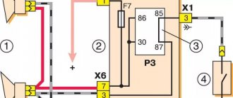
The cause of non-functioning electrical equipment in the car (for example, fuel pump, heated seats, heated windows, power windows, etc.) may be a faulty relay. Let's look at a simple way to test a car relay for functionality with your own hands.
Connection diagram for 4 and 5 contact relays:
Refinement stages
Wiring
It is easy to modify or replace wipers. To do this you need to take several sequential steps:
- Disconnect the negative cable from the battery;
- Pull the wiper towards you;
- Remove the existing brushes;
- If there is a decorative trim, remove it;
- Unscrew the mounting bolt, thereby removing the old wiper;
- Compare the dimensions of the old and new cleaner;
- Ideally, the new device should not exceed the old one by more than 20 millimeters;
- Reverse the assembly procedure.
As you can see, changing windshield wipers is not difficult. But with the repair procedure, everything is somewhat different. But following the instructions, even an inexperienced VAZ 2110 owner will be able to do everything with his own hands.
You can’t go far without wipers in rain or snow, so today we will discuss the topic of why wipers do not work on a VAZ 2110, and what to do in such a situation.
Design and principle of operation of the switching device
An electrical relay is a part that is used as a switch thanks to the control signals that are supplied to it through an electrical circuit. The line connected to the device is called controlled; the line through which a command is already being sent to it - the manager.
It is used in domestic conditions and in all industries to automate various operations. If a household or electrical appliance fails, you must first check the functionality of the switching element. But first it is recommended to familiarize yourself with the types and operating principles of relays.
Principle of operation
The part is an electromagnet, which includes an inductor, an armature and a contact group.
Each component is mounted on a base and enclosed in a protective housing. The armature is located on top of the magnetic system core; in the initial position it is held thanks to a spring, which has the shape of an L-shaped movable plate.
The lower part of the base is equipped with a contact group; on the contrary, the same number of contact bases is mounted. The contacts are ductile because they need to be brought out outside the protective housing to form the device terminal.
The principle of operation of the relay is based on its ability to influence conductive objects with its electromagnetic field. As soon as voltage is applied to the winding terminals, current begins to flow through the relay. When its value reaches a previously programmed value, two forces are formed in the winding, which press the armature to the surface of the coil.
Taking into account the design features, the initial position can be not only closed, but also open. In the second case, when voltage is applied, the line will open. The contacts of the device will return to their original state as soon as the signal of the required magnitude is removed from the relay terminals.
Device design
Wiper circuit
First, let's try to understand how the windshield wiper circuit on the VAZ 2110 works and what components form a solid unit called a windshield wiper.
| Device | Characteristic |
| Electric motor | It is responsible for rotating the wipers at different intensities. The electric motor contains a gearbox, and the motor itself operates due to the DC current supply. There are three built-in blades in the armature of the engine, providing three operating modes of the windshield wiper - fast, slow and with pauses. Although it is believed that the VAZ 2110 has only two brush rotation speeds |
| Electrical components | This is a steering column switch, a wiper relay, which allows you to activate the intermittent movement of the brushes. Plus, don't forget about the switch. The entire electrical system is integrated into wires running through a bimetallic heat-resistant fuse. It is important to note that both relays and fuse F5 are located in the mounting block, and the bimetallic fuse and switch are in the motor gearbox |
| Windscreen wipers | At the same time, the size of the wipers on the VAZ 2110 may be different, which we will talk about later. They differ in shape, material of manufacture, device |
| Mechanical drive | An important component, which, alas, often breaks down at “ten” |
Types and characteristics
Depending on the element base used, relay regulators are divided into the following types:
- Microcontroller or microprocessor based. Their peculiarity lies in the inclusion of a working algorithm in the built-in chip. Used in expensive cars, such as BMW or Audi.
- Relays are based on switching relay contacts to cut off and stabilize the performance of the electrical network.
- Integrated relays are widely used in the automotive industry. The operating principle is based on solid-state switching parts or integrated semiconductors.
- Hybrid transistor-relay devices and simply transistor ones are based on semiconductor elements. They were actively used in industry until the early 90s.
Device
General structure of the windshield wiper system:
- As everyone knows, the wipers are driven into a state of “swinging” of varying speeds by an electric motor, which has a built-in gearbox, and the motor runs on direct current. Three brushes are “built-in” in the motor armature, with the help of which the VAZ 2110 wipers operate in three modes. There are only two speed frequencies: one for fast movement (for example, during a rainstorm), the second for slow or intermittent movement;
- The electrical component is the switch (under the steering wheel); relay switching on intermittent mode; additional relay; switch. The entire electrical system is connected by wires (in blocks) through a thermal bimetallic fuse. Moreover, both one and the other relay, as well as fuse F5, are located in the mounting part, and a bimetallic fuse with a limit switch is located in the electric motor gearbox;
- Directly windshield wipers. Their size is important, as well as the material, shape, and device. Check whether the already installed ones squeak, whether the mechanism and the leash are working, perhaps they need improvement;
- Mechanics. First of all, this is a drive that can break.
Wiper diagram for VAZ 2110
Symptoms of a problem
Before checking the relay with a multimeter, you should familiarize yourself with the main signs that the part has failed.
- There are cases when, as a result of the failure of the voltage regulator, the battery boils.
- When the ignition is turned on, the control light on the dashboard does not light up (however, this can be a symptom of other types of malfunctions, for example, a contact has fallen out or burned out).
- The dynamic characteristics of a household appliance or car are reduced, especially when the engine reaches high speeds.
- After starting, the battery indicator does not go out on the dashboard, which indicates a battery problem.
- The indicators on the dashboard simply turn off if the engine speed during operation exceeds 2000 rpm.
- The brightness of the headlights depends on the engine speed. It is quite simple to verify this - you need to stand in front of the wall in the dark and turn on the headlights. The brightness of the glow will change depending on how hard you press the gas.
- The battery is regularly discharged.
These signs may indicate other malfunctions, but first of all it is recommended to check the relay regulator.
Windshield washer does not function
Since not only the cleaner, but also the washer is responsible for the cleanliness of the windshield, it is worth considering the malfunctions of this device. The design of the mechanism consists of the following elements:
- washer pump;
- fluid reservoir;
- nozzles (jet);
- auxiliary parts (wiring, tubes).
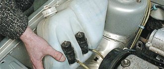
The washer reservoir is located in the engine compartment and is held on a special bracket. Water or a special glass cleaning liquid is poured into it. The tank also contains a pump, through which the liquid is supplied through tubes to the nozzles, which spray it over the surface of the glass.
The washer reservoir is located under the hood, and a pump is installed inside the tank
Despite its simple design, the washer also sometimes fails and there may be several reasons for this:
- pump failure;
- fuse blown;
- kinking of tubes;
- breakdown of the steering column switch;
- poor contact on the power supply circuit.
Pump check
The washer pump on Zhiguli cars often does not work due to poor contact on the electric motor itself or wear of the plastic elements of the device. Checking the serviceability of the electric motor is quite simple. To do this, open the hood and pull the washer lever on the steering column switch. If the mechanism does not make any sounds, then the cause should be sought in the power circuit or in the pump itself. If the motor hums and fluid is not supplied, then most likely a tube has fallen off the fitting inside the tank or the tubes supplying fluid to the injectors have become bent.
A multimeter will also help you verify whether the pump is working or not. Using the probes of the device, we touch the washer contacts when the latter is turned on. The presence of voltage and the absence of “signs of life” of the motor will indicate its malfunction. Sometimes it happens that the device works and pumps, but due to clogged nozzles, liquid is not supplied to the glass. In this case, cleaning the injectors with a needle is required. If cleaning does not produce results, the part is replaced with a new one.
Washer nozzles are replaced due to a blockage that cannot be removed
If the fuse fails or the problem lies in the steering column switch, then these parts are replaced in the same way as described above.
Reasons for failure of the relay regulator
In order to minimize the likelihood of repeated breakdowns in the future, you should familiarize yourself with the main reasons for device failure.
- Short circuit in any part of the electrical circuit, including interturn short circuit of the excitation winding.
- The regulator may also fail if the diodes break down or the rectifier bridge breaks down.
- Incorrect connection or reverse direction to the battery terminals.
- Penetration of moisture or large amounts of dust into the generator and/or the regulator itself (such cases are common during heavy rainfall or when washing the car).
- Mechanical damage to the working unit.
- Natural wear and tear, end of service life.
- Initially, the quality of the purchased product is questionable.
Alternative solutions
Most car owners of the domestic “ten” are accustomed to replacing worn out and faulty windshield wipers with similar ones.
Often this happens because they do not see alternatives and are not familiar with them.
But this size can be increased to 530 millimeters . It is not recommended to install more, since this way the windshield wiper will not be able to work effectively, and the drive simply will not cope with the load. As a result, too long brushes cause squeaking and jerky work. Plus, don’t count on a long service life of the wiper mechanisms.
The original windshield wipers for the 10 are quite good. But there are more expensive, but also more highly efficient, high-quality devices.
Today it is fashionable to use frameless wipers, especially from Bosch. Their advantages lie in their compactness and a special, reliable leash mechanism.
But as practice shows, on the windshield of the VAZ 2110, as well as other VAZ models, they do not look very nice, because the fasteners on the leash turn out to be massive. Although if you modify them a little, you will get a very good result.
Preparing to test the relay for functionality
Checking the relay will not take much time if all the preparatory work is done correctly.
Before you begin diagnosing the device, you need to determine the purpose of the pins of the part being tested. To do this, use the documentation supplied with the device; it contains all the diagrams and operating features, and the characteristics of the device.
There are common cases when the operating diagram is depicted on the relay body itself. Contacts are represented by dots; they are connected by an inductor, the switching elements are straight lines with a dotted line. The power supply pins are shown schematically as a rectangle.
If the relay is built into the circuit, you need to visually inspect the state of the bus and power traces on the board itself. To check the relay with a tester, you can use both digital and analog instruments. No preliminary preparation or setup of testers is required.
In addition to the tester, you need to prepare a regulated power supply. For the results to be reliable, the relay must be removed from the circuit.
The functionality test is carried out in several stages:
- winding;
- normally closed position;
- normally open state.
Then you can proceed directly to diagnosing the relay.
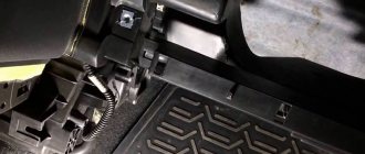
Repair
Having skillful hands and basic knowledge of how the wiper mechanism works, there is no need to contact a paid service to make repairs or change windshield wipers. Replacing the windshield wiper motor on a VAZ 2110 is also quite simple.
Parsing is carried out in this way:
- Remove the dashboard;
- On the left we find a relay screwed to the body. If the relay turns out to be faulty, then repair is unlikely to help it; a replacement is needed;
- We check the fuse responsible for the wiper drive;
- We disassemble the steering column to inspect the switch. If it turns out that the switch has insulation damage or other problems, it means it needs to be replaced;
- We unscrew the motor from the body and check for functionality. If there is a minor problem, it can be repaired, or perhaps it will need to be replaced, along with the relay. There is no point in repairing the relay separately - its cost is cheap;
- Inspect the drive; one of the possible faults is that its pulley has broken.
Diagnostics of windings and contact groups
The winding is an inductance coil on which wire is wound in a spiral.
It is characterized by a certain resistance, which is calculated according to Ohm's law. The resistance value should range from 10 to 100 Ohms. Diagnostics of the winding allows you to find out whether its integrity is compromised. Functionality testing is carried out in several stages:
- The multimeter is turned on in resistance testing mode. On the instrument panel this mode is indicated by the symbol – Ω, the range is set within 2 kOhm.
- One measuring wire is connected to the socket, and the second to the COM.
- The wire probes touch the relay terminals.
The resistance of the inductor can be determined by the deflection of the arrow.
Checking contact groups is carried out in two stages. First, the resistance must be measured offline, and then when voltage is applied to the coil. When checking, you will need a power source, you need to take care of this in advance.
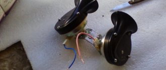
Wiper intermittent relay
The rear wiper operates intermittently instead of continuously. Delay 15 sec.
The goal of our work is to operate the rear window wiper in intermittent mode with an interval of about 12-15 seconds (in our opinion, this interval is optimal in the absence of a rear “correct” spoiler). To achieve the goal, we set the following tasks:
1. Implement a simplified diagram of the operation of the VAZ-2108 windshield wiper. To do this, we need to receive a signal from the electric motor of the rear wiper drive that the brush has arrived in place. The signal must be supplied by shorting the wire to ground.
2. Select a resistor to create the operating frequency we need.
3. Hide (secure) the relay under the dashboard (or in the back door) so that it does not create unnecessary noise when the car is moving.
To complete the tasks we will need:
1. Soldering iron (IMHO, it’s better to solder everything - less chance of snot). 2. Female type terminals – about 10-15 pieces. 3. Relay type 524.3747. 4. Side cutters (nippers). 5. Electrical tape. 6. Installation wire – 1 m. 7. Heat-shrinkable tubes. 8. Block for relay contacts. 9. Resistor value
Next, point by point:
1. In order for the circuit to repeat the figure-of-eight, we need to get the mass from the motor at the moment when the brush comes into place. To do this: a. Remove the rear door trim. b. We remove the rear wiper along with the leash. V. Unscrew the nut securing the electric motor to the body (outside, under the leash mount). d. Unscrew the two nuts securing the electric motor to the body (inside the door). d. Remove the motor. e. Turn on the soldering iron and unsolder the blue-white and blue wires from the right contact on the motor. and. We solder the blue and white wires together and insulate them with electrical tape. h. We solder a piece of wire onto the freed contact, and connect its other end to ground (the easiest way is to put it under the bolt).
All. The engine gives us mass at the moment when the brush is in place.
2. The selection of a resistor is carried out using the scientific method. Optimal for me is 16 KOhm, which creates a pause of about 15 seconds. A. Open the pause relay. b. We unsolder the resistor from the relay, which comes directly from contact J of the relay. V. We solder the required resistor in its place.
3. IMHO, it is better to hide the relay under the panel on the left, because the doors are not and will not be airtight, and water at +12 V can cause trouble.
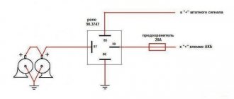
In general, the connection diagram looks like this:
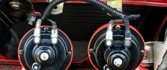
Installing a rear door wiper relay with pause adjustment (option 2131).
Product 72.3777-01 manufactured by ENERGOMASH was chosen as a relay due to the easiest and most logical installation, in my opinion. The diagram was published by Electromaster on page 9 of the “Rear wiper” topic. Just in case:
Removing the inner trim of the rear door:
Remove the left shelf and rear trim:
We crimp the wire with the mother (no more than 0.75 square meters, the length is with a margin, then we will cut it) and pull it through the back door, after first removing the seal in the door. I used a 2.5 sq. wire to pull it through, running it into the hole that includes the wiring harness and washer tube. Having caught it, he tied the end opposite from his mother with electrical tape and pulled it out:
Next we look at where to install the relay. I had two ears in which the assemblers did not put clamps:
Having selected the required length of wire to the relay, I tied the wire with electrical tape to the already laid harness:
In the niche near the washer reservoir, I used electrical tape to attach a wire to the existing wiring harness. By touch I found the wires going to the washer pump. We connect the wire stretched through the door to a non-black one! Option in the photo:
In accordance with the diagram, we assemble the adapter into the gap in the connection block for the rear wiper gear motor. (For those who are especially attentive! In the photo, the blue wires in the relay block should be swapped! Damn, I spent an hour checking until I understood what was going on. When I understood, I forgot to take a photo):
We thread the wires so that they do not dangle:
We install the rear door trim, side panel, harness seal in place and enjoy the result.
| On VAZ cars of the first releases, up to 2107, as well as 2121, 21213, there are two windshield wiper control modes - continuous and intermittent with a fixed interval (4.6 s) of brush movement. On VAZ-2110 cars and their modifications, in addition, an increased frequency of brush strokes in continuous mode is additionally provided. However, for effective operation of the windshield wiper in intermittent mode with varying intensities of precipitation, a fixed periodicity in most cases is not enough. The device works as follows. The standard dual key switch SB1 of the windshield wiper operating modes has three positions: “0” – the windshield wiper is off; I – cyclic (with pause) operating mode; II – continuous operating mode of the windshield wiper. In position II, power (+12 V) is supplied directly to the wiper motor winding M1 through the int contact of connector XR2. In this case, limit switch SB2 does not affect the operation of the engine. In position I of the operating mode switch SB1, +12 V voltages are supplied to pin 3 of the electronic relay circuit. This state of SB1 is shown in the drawing. Since capacitor C1 is initially discharged, there is no voltage at the base of transistor VT1 relative to its emitter, and VT1 is locked. In this case, transistor VT2 is unlocked by the base current through resistor R5 and motor winding M1. Accordingly, thyristor VS1 is unlocked, receiving a positive potential to the control electrode through resistor R7. The thyristor instantly goes into a conducting state and “remembers” it. Through terminal 4 of the electronic relay circuit, +12 V is supplied to the motor winding, and the windshield wiper begins to move the blades. Limit switch SB2 switches almost simultaneously. In this case, the thyristor VS1 is short-circuited by its “int-C” contacts (connector XR2) and goes into a non-conducting state, but the supply voltage to the motor does not stop. Through resistor R6, transistor VT3 is unlocked, providing fast charging to the voltage of the power supply of capacitor C1 through resistor R4, unlocking transistor VT1 through resistor R3. This in turn leads to the blocking of transistor VT2. After the brushes make a double stroke and return to their original position, the state of the limit switch SB2 changes, the “int-C” contacts open, and the “int-F” contacts close. Motor M1 stops because thyristor VS1 is in a non-conducting state. VT3 is locked. A pause in the wiper cycle begins to form. Capacitor C1 is discharged through resistors R1, R2, R3 and the base junction of transistor VT1. The discharge (pause) time can be adjusted from 0.5 to 20 with potentiometer R1. A decrease in the charge of C1 leads to the turning off of transistor VT1. Accordingly, transistor VT2 (transistors VT1, VT2 must be of the KT209K type) and thyristor VS1 are unlocked. The motor is supplied with supply voltage through thyristor VS1, and after a very short period of time, power is supplied by limit switch SB2. The process of moving the brushes is repeated. Capacitor C2 reduces sparking of contacts SB2 of the limit switch and interference with the operation of radio equipment in the car. Its value is not critical; it can be reduced by 10 times. Protective diode VD2. It can be replaced by KD105, KD221, KD208, KD209 and similar ones. As VS1, you can use KU202 thyristors with any letter. The use of KU201 is possible, but the reliability of operation will be lower. The printed circuit board allows the use of thyristors in a plastic case of type KU202N-1 or T106-10. In this case, the printed circuit board can be shortened by 15 mm. The maximum pause duration can be increased if desired. To do this, it is enough to proportionally increase the resistance of the potentiometer R1 or the capacitance of the capacitor C1. Now a few words about dynamic engine braking. The fact is that the drive mechanism of the windshield wiper blades of Zhiguli cars has small friction losses. If to stop the engine you use only de-energizing the engine in the initial extreme position of the brushes, then by inertia the engine rotor will rotate a little more, and the brushes will advance an additional 3-5 mm. In principle, this does not create any particular inconvenience for the driver, but this disadvantage is easy to get rid of. In the standard design with the PC514 relay, the “int-F” contacts of the limit switch were used for this, which short-circuited the winding of the de-energized motor during a pause. In the proposed electronic relay circuit for dynamic braking of the engine, it is enough to install resistor R9. Its value is non-critical from 4.7 to 10 ohms. In fact, little power is dissipated on the resistor, since current flows through it only briefly during normal operation of the relay, but an emergency condition of the windshield wiper cannot be ruled out, for example, “sticking” of the “int-F” contacts of the limit switch. Therefore, it is advisable to use a powerful resistor of the PEV-10 type. As mentioned earlier, the use of an electronic windshield wiper relay does not require changes to the standard wiring diagram of the Zhiguli car. A failed PC514 relay should be disassembled and a harness of four wires with a connector plug should be unsoldered from it. The colors of the wires and their connection to the plug are shown in Fig. 4. If dynamic braking is not used, and this is quite justified to simplify the design, then the end of the unused wire should be insulated. The wires of the harness are soldered to the electronic relay board, and the board itself is placed in the PC514 case and covered with an insulating bottom lid that fits the size of the board. Potentiometer R1 is placed in any place convenient for the driver on the car panel, for example, near the windshield wiper operating mode switch. More than five copies of the electronic relay were manufactured and installed on cars. There was no selection of elements. All drivers report a wide range of pause intervals. The operation of the windshield wiper motor has become more stable. In conclusion, it should be noted that the proposed electronic relay is the simplest technological solution to the problem, therefore, the digital relay circuits found in the literature were not considered unnecessarily complicated, especially since neither the exact value of the pause nor its stability are unimportant for the driver. |
Abnormal voltage readings on the multimeter
If the multimeter shows low voltage in the battery, the battery will simply stop accepting charge. As a result, the car may not start, the indicators on the dashboard may stop working, and troubles may arise while driving.
If the voltage is increased, there is a possibility that the level of electrolyte in the battery bank has decreased, or it has simply boiled away. Another characteristic feature may be the formation of a white coating on the walls of the body. When recharging, the battery may begin to behave unpredictably.
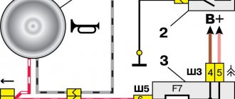
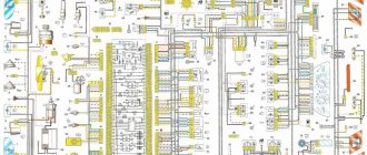
Where does which wire go, or just a diagram
Connecting wipers and washer
“Plus” power is supplied from the ignition switch through fuse No. 2 at 10 Amp of the mounting block. The permanent “plus” goes along the black and yellow wires to contacts “4” of the connectors of the gear motor and the steering column switch. It should not disappear even when the switch is in the “off” position. The blue wire supplies “+” 12 V power to the motor when the switch is in the “continuous mode” position. On the blue-white wire, in the “off” position there should be a “minus”, and in the “continuous mode on” position the “minus” is turned off. This is done to slow down the motor when the power to the closer is turned off.
The red wire supplies the relay with “+” 12 V from the switch when the intermittent mode is turned on. At the moment of operation, contacts “2” and “4” close, and “1” and “3” open, the motor starts working and the brushes make one or two movements. Then “+” 12 V is turned off, and contacts “1” and “3” are closed to each other and to “minus”. The motor stops for a few seconds and then the cycle repeats.
The washer pump motor is connected to “+” 12 V constantly with a black and yellow wire through the same fuse No. 2. “Minus” is applied when you press the windshield wiper lever from bottom to top.
Video about how a windshield wiper works
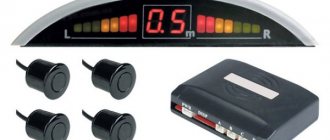
How to ring a relay
We are preparing a multimeter.
We put it in resistance measurement mode at 200 Ohms. We close the probes, 0 should appear on the display instead of 1 - the multimeter is working and ready for use. For a four-pin relay. We check the resistance on pins 85 and 86. It should be from tens to hundreds of ohms.
We check the resistance on pins 30 and 87. Without voltage on 85 and 86, the multimeter should show 1.
We apply control voltage to 86 and 87. We measure the resistance 30-87. Should be 0. The relay is working properly.
For a five-pin relay the order is as follows. Without control voltage, we check circuit 85-86 in the same order. There should be a value from tens to hundreds of ohms.
Then we check the circuit resistance 88-30. 0 on the display indicates correct operation of the relay. There should be one between pins 30 and 87. The same as between 88 and 87.
Checking the starter regulator
To check the starter regulator relay without removing it from the car, you can use a multimeter and test all the wires that go to it. To do this, they are first disconnected from the regulator. The multimeter is switched to resistance measurement mode, the disconnected wires are checked.
If everything is normal, then the conductors are returned to their place. The voltage at the battery terminals is measured with the engine off. The multimeter is switched to DC voltage measurement mode in the range from 0 to 20 Volts. The probes attach to the battery terminals. The device should show 12.2-12.7 V. If 12 volts or lower, then it needs to be recharged.
Then the engine must be started and checked again with the same measurements. If the voltage is in the range of 13.2-14 V, then this is normal. We add engine speed to 2000 per minute and measure again. Normally, the multimeter should show between 13.6-14.2 V. We also add revolutions to 3500 per minute.
We take readings. They should not exceed 14.5 Volts. If the value does not change and remains 12.7 Volts, as when the engine is turned off, or even decreases, then the regulator relay is faulty. Therefore it needs to be replaced. If 14.5 Volts are exceeded, the regulator must also be changed.
Sometimes the question arises of how to test a relay with a multimeter if there is no access to the regulator. Then you need to remove it, and to check it you must have, in addition to the tester, a charger with a voltage regulator and a light bulb. The following scheme is assembled from them. The charger is connected to the input terminals of the regulator, and the light bulb is connected to the output (thick) terminals. A multimeter monitors the voltage at the regulator input. By charging we change the voltage from 12 to 15 volts. The light should go out at 14.5 volts. If this does not happen, the regulator is faulty and must be replaced.
Definition
Before you test a relay with a multimeter, you need to understand what a relay is. This is a device designed to regulate the current of a car's alternator, preventing it from overcharging the battery. Therefore, because of this element, batteries last longer.
By and large, a relay is a voltage stabilizer that does not allow voltage greater than 14.5 Volts. This device is extremely accurate and is a must for all types of machines. However, there are several types of relays.
Fuses and relays VAZ 2110 - 2112, electrical diagrams
If some devices on your VAZ 2110 or VAZ 2112 , fuses or relays may be to blame. At the very least, the first thing you need to do is check them, and then draw some conclusions regarding the malfunctions.
Correct diagnosis of many electrical problems will allow you to accurately determine the cause of the inoperability of a particular unit. To find out what the fuses and relays of the VAZ 2110 - 2112 are responsible for and how to find the right one, read this article.
As in many other cars, in the VAZ-2112 and VAZ-2110, when the engine is turned off, the devices are powered directly from the battery. When the engine is running, voltage is supplied to the devices from the generator, which simultaneously charges the battery. If the current exceeds the permissible value or a short circuit occurs, the circuit fuse will blow. Powerful electrical appliances are connected via relays.