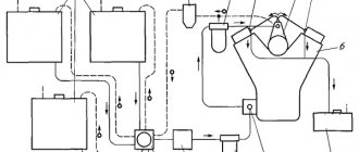
Air or a fuel-air mixture, depending on the type of engine (diesel, injection or carburetor), enters the cylinders through the intake manifold. The main purpose of the intake manifold is to ensure uniform distribution of air or working mixture between the cylinders. The efficiency of the motor directly depends on this. In addition, other components, such as a carburetor or throttle valve, can be mounted on the manifold.
The principle of its operation is quite simple: air or its mixture with fuel, entering through the inlet, is divided into several streams, according to the number of engine cylinders. The pistons, moving downwards, create a vacuum in the manifold, which can reach large values. This partial vacuum is also used to neutralize crankcase gases. They enter the intake manifold through the engine crankcase ventilation system, mix with the fuel-air mixture or air and are burned in the cylinders.
Until recently, the main materials for the manufacture of the intake manifold were aluminum, iron and cast iron. This created certain difficulties. The fact is that the collector itself gets very hot during engine operation and heats the air that is currently inside it. The air, in turn, expands and enters the cylinders in a smaller volume, as a result of which fuel consumption increases and engine performance deteriorates.
As an alternative to metal, since the late 90s, now the last century, plastic-based composite materials have been used on many cars. Due to low thermal conductivity, such an intake manifold does not heat up as much, as a result, the cylinders are better filled with air, and the engine power per unit of fuel increases.
Turbulence in the intake manifold
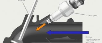
This paragraph does not apply to engines with direct injection. The fuel enters the intake manifold in a finely atomized form and is then mixed with air. Some of it may settle on the walls of the intake manifold under the influence of electrostatic forces. This phenomenon is extremely undesirable, since as a result, much less fuel will enter the cylinders, and the air-fuel proportion calculated by the electronic control unit will be violated in the direction of increasing the volume fraction of air.
Turbulence helps combat fuel condensation. Under its influence, the fuel is better atomized, and its combustion occurs more completely. As a result, engine power increases and the risk of detonation decreases. To ensure the appearance of turbulence, the inner surface of the intake manifold is not polished, but rather made rough. Here it is important to achieve the optimal value of turbulence, since as it increases, pressure drops begin to occur inside the intake manifold, and engine power decreases.
Replacing parts
To replace the pneumatic chamber you do not need complex tools or lengthy manipulations. First, the fastening is unscrewed and the rod is removed, after which the camera is removed and a new one is installed. Sometimes corrosive destruction of the body of the container itself is possible, for which it also needs to be checked periodically.
Valve tools: screwdrivers, wrenches and pliers
To replace the intake manifold flap control valve you will need a set of screwdrivers, pliers, and wrenches. The whole job will take no more than twenty minutes:
- First, unscrew the screws securing the strip on which the valves are located;
- New valves are installed;
- The entire structure is screwed into place;
- The resistance is measured - its value should be from 33.2 to 33.3 Ohms.
The replacement is short and simple, so it can be done even in the yard of the house, taking the necessary tools.
Intake manifold valve in a car
It very rarely happens that the valves are destroyed and clog the manifold with debris. This usually happens on low-quality engines, due to overheating of the motor or if the valves themselves have been replaced with a counterfeit analogue.
Valve location
Shape and volumetric efficiency
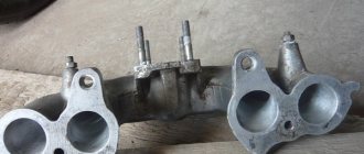
One of the most important parameters of the intake manifold that determines its efficiency is its shape. The basic rule that all engineers adhere to is that the intake manifold should not have any angular shapes , as this will provoke pressure drops and, as a result, worse filling of the cylinders with air or working mixture. Therefore, all collectors have smooth transitions between segments and rounded shapes.
The vast majority of current collectors use runners. They are separate pipes diverging from the central entrance of the manifold to all available intake channels in the cylinder head. Their task is to use a phenomenon called Helmholtz resonance. The operating principle of the design is as follows.
At the moment when suction occurs, air flows at a very high speed through the open inlet valve. When the valve closes, the air that did not have time to enter the cylinder retains a large impulse, which means it presses on the valve, resulting in a high-pressure zone. Then pressure equalization occurs, with lower pressure in the manifold. Due to the influence of inertial forces, leveling occurs with fluctuations: first, air enters the runner at a pressure lower than in the manifold, then at a higher one. This process occurs at the speed of sound, and before the intake valve opens again, oscillations can occur many times.
The smaller the diameter of the runner, the greater the change in pressure due to resonant air vibrations. As the piston moves down, the pressure at the outlet of the runner decreases. This low pressure pulse then travels to the manifold inlet where it turns into a high pressure pulse that travels in the opposite direction through the runner and valve, after which the valve closes.
To achieve the maximum effect from resonance, the intake valve must open at a strictly defined moment, otherwise the result will be the opposite. This is quite difficult to achieve. The gas distribution mechanism is a dynamic unit, and its operating mode is directly dependent on the crankshaft speed. The pulses are synchronized statically, the synchronization depends on the length of the runners. The problem is partially solved by selecting the length for a certain speed range at which the greatest torque is achieved. Another option is the use of systems for changing the geometry of the intake manifold and electronic timing control.
Is technology necessary?
The sequential formation of the intake tract, which is created by the throttle, filter, and valves, has a strong influence on the process of filling the cylinders with fuel. The air mixture that passes through this path fluctuates significantly. Together with other parts they form a shock system. This leads to the dependence of the processes of filling the cylinders on the factors of the oscillatory configuration.
Obtaining the efficiency of the system with the required parameters and the required range seems to be an extremely complex procedure. As a consequence, there is the idea of changing the performance of the oscillatory system during operation. After conducting research, it can be stated that the engine works well at high speeds with a short intake manifold. The opposite is true at low revs; efficiency can be achieved with a long intake tract.
It is logical that the conclusion arises to create an intake tract of variable length. This will allow them to be controlled taking into account different loads and speeds.
Intake manifold geometry modification systems
Since the fixed length of the intake manifold ensures high-quality filling of the cylinders only in limited ranges of crankshaft rotation frequencies, an intake manifold with a geometry changing system is considered more preferable. Either its length, or diameter, or both parameters can change.
Variable length intake manifold
It is used on naturally aspirated power units, both gasoline and diesel. When the engine operates at low speeds, the length of the manifold must be large to achieve high torque and throttle response; at high speeds, it must be short so that the power unit can develop maximum power. To change the geometry, a valve included in the engine control system is used. It switches the manifold from one length to another.
The variable length intake manifold works as follows. When the intake valve closes, the air remaining in the manifold begins to oscillate, the frequency of which is proportional to the length of the manifold itself and engine speed. When resonance occurs, a pumping effect appears (resonance boost). As a result, air is supplied to the opening intake valves under increased pressure.
In engines equipped with supercharging systems, such an intake manifold with variable geometry is not used, since air is forced into the cylinders. In such power units, the shortest manifolds are used, thereby reducing the dimensions and cost of engine production.
The system for changing the geometry of the intake manifold is called differently by different manufacturers:
- BMW calls it Differential Variable Air Intake (DIVA);
- for Ford it is Dual-Stage Intake (DSI);
- in Mazda cars the system is called Variable Inertia Charging System (VICS), in some cases Variable Resonance Induction System (VRIS).
Variable intake manifold
Can be used on any engines, including those equipped with supercharging. As the cross-section decreases, the speed of the air passing through the manifold increases, therefore, mixture formation improves and the working mixture burns more completely.
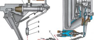
The system for changing the geometry of the intake manifold has the following device. The intake port of each cylinder is divided into two - one for each intake valve, inside one of which there is a damper. The damper is opened and closed by a vacuum regulator or an electric motor.
When the engine is running under light load, the dampers are closed, air is supplied through one channel and enters the cylinder only through one valve. This creates turbulence in the cylinder, which improves mixture formation and the quality of fuel combustion. Under load, the dampers open and air is supplied through both channels, thereby increasing engine power.
There are many variations of such systems, for example, Opel has a system for changing the geometry of the intake manifold called Twin Port, Ford has two types - Intake Runner Control (IMRC), Charge Motion Control Valve (CMCV), Toyota and Volvo have Variable Induction System or Intake System (VIS).
Manifold tuning
Engine tuning is a whole range of work to refine its individual components and parts. The intake manifold can also be modified to improve engine performance.
Tuning this part has two directions:
- to overcome the negative influence of its form;
- for finishing the internal surface.
What does form have to do with it?
The flow of air or working mixture in the manifold is uneven due to its shape. If the manifold is asymmetrical, then the largest amount of air or fuel-air mixture will enter the first cylinder, and less will enter each subsequent one. The symmetrical one also has a drawback: there, the largest amount of air enters the middle cylinders. In both cases, the cylinders operate unevenly on mixtures of different qualities. As a result, engine power decreases.
Tuning, in this case, involves replacing the standard intake manifold with a multi-throttle intake system. Its design is such that the air flows supplied to the cylinders are independent of each other, since each of the cylinders is equipped with its own throttle valve.
"Internal" work
If there is a lack of funds, tuning can be done more cheaply, almost for nothing. Inside the reservoirs there are almost always a large number of irregularities and tides, and the surface is rough. All together, this causes unnecessary turbulence that interferes with the quality filling of the cylinders. During measured driving, this phenomenon is almost unnoticeable, but if you want to achieve greater efficiency from the engine, you need to fight these shortcomings.
Tuning a standard intake manifold involves grinding its inner surface in order to remove tides and roughness. You need to grind not until a mirror appears, but only until the entire surface is uniform. If you overdo it, drops of fuel will condense on the walls and tuning will give a completely opposite result.
Finally, in order for the tuning to be as complete as possible, you need to pay attention to the interface between the manifold and the cylinder head. Often, a step remains in this place, interfering with the normal flow of air flow, which must be eliminated (this is where cylinder head tuning begins).
What else is worth reading
Clutch housing
The principle of operation of an injection engine
How can you burn the clutch on a car?
Gas distribution mechanism
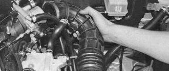
Cleaning with removal
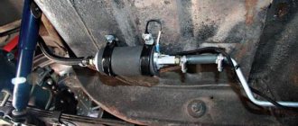
If you hear characteristic knocking sounds from the intake manifold while the engine is running, this indicates that there is dirt in the manifold. Cleaning must be performed to restore normal operation. Let's see how this is done using the example of cleaning the Astra intake manifold.
First of all, the car is lifted on a lift. Then unscrew the manifold bolt that secures it to the ramp. Remove the throttle valve, remove the sensors and pipes. Now unscrew the bolts securing the manifold to the engine and dismantle it. Remove the cover.