Anti-lock braking system (ABS) is a system that prevents the wheels from completely locking during emergency braking. This solution is one of the first electronic active safety systems that began to be universally installed on cars.
Today, such a system is an integral part of almost any modern car, even in the budget segment. Also in developed countries, the mandatory presence of ABS in a car is enshrined at the legislative level.
At the same time, many drivers know that the car has this system, but do not fully understand what ABS is and how this solution works. In this article we will look at how ABS works, what it is, as well as what functions such a system performs and why it is important to monitor the serviceability of the ABS in a car.
What is ABS in a car in simple words
ABS in English means Anti-Lock Breaking System. This is a security system designed to perform 3 main tasks:
- prevents wheel locking when braking;
- provides traction when cornering when you press the brake pedal;
- reduces braking distance.
ABS is most effective when cornering in difficult road conditions (for example, heavy rain or snow). The system is designed to eliminate the need for so-called impulse braking and distribute the braking force throughout the braking system so that no wheel locks.
Therefore, it is able to maintain the degree of slip of each wheel in the range from 10 to 40% (full locking occurs at 100% degree of slip): only in this case can the driver correct the trajectory if he has to press the brake pedal in a turn. Constantly monitoring traction is also useful when braking on a straight road. Wheel locking on dry asphalt will damage the tire, and on wet asphalt it will almost double the braking distance.
A car with locked wheels slides straight when turning. ABS is designed to prevent this and maintain an optimal level of slip at each wheel (10-40%), giving the driver the opportunity to correct the trajectory.
ABS is such a popular technical innovation that almost every driver has heard of it. Not surprising: it began to be introduced before World War II, and began to be used on airplanes in the 1950s. It first appeared as standard equipment in a passenger car in 1978 on board the Mercedes W116, and 3 years later in trucks of the German brand. Then it began to be used on motorcycles and buses, and later other cars began to be equipped with ABS.
Generations and species
The modern system installed on a car is four-channel. It includes two valves for each wheel, as well as one pressure accumulator and shock-absorbing chamber per circuit (of which there are two).
In general, this system already has 5 generations. The first of them appeared in 1978, the second replaced it in 1980 and was installed until 1995, after which the 2nd generation replaced the 3rd. The modern 4th generation of the system appeared in 2003, and now the 5th generation is in use, which continues to be used to this day.
In terms of design features, the four-channel system is the latest and most technologically advanced. But it was preceded by:
- single-channel system (it used only two valves, which regulated the pressure in all lines simultaneously. It is noteworthy that in the single-channel type the system usually made adjustments only in the drive axle mechanisms, that is, the ABS worked only with two wheels);
- two-channel (in this type of ABS, the brake mechanisms are divided along the sides, each of which has its own set of valves. That is, one channel combines the mechanisms of the front and rear wheels of one side);
- Three-channel (it provided one set of valves for the wheels of the rear axle, and the front ones were each equipped with its own channel).
Nowadays, these three types of ABS systems are found only on older cars.
Why do you need ABS and its diagram?
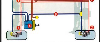
Many car owners, although they have heard about this system, have no idea how ABS works on a car. Each wheel has a sensor that transmits information to the controller about the current speed of rotation of the wheel. A modern ABS system consists of the following components:
- pressure modulator with electronic controller and pressure-regulating valves (previously modulators and controllers were separate components);
- wheel speed sensors (one for each wheel).
Sensors mounted on the wheel hubs constantly monitor the slippage of each wheel and immediately inform the ABS control unit if there is a tendency to lock up. Using a modulator, it distributes pressure from the master cylinder in such a way as to maintain the movement of the wheel. This element reduces the pressure as wheel slip increases and increases it again when traction is restored. The driver perceives the operation of ABS by the characteristic vibration of the brake pedal. Do not under any circumstances release the pressure at this point; on the contrary, it should be increased in order to utilize the potential of the ABS.
How effective are anti-lock brakes?
It doesn't take a genius to figure out that if the aviation industry and car manufacturers have adopted ABS, it's probably a good thing. The fact that it is a required feature on all new cars sold indicates that the government and other regulators have confidence in the system.
Here are four benefits of ABS:
- Vehicles equipped with ABS are less likely to be involved in a fatal accident.
- ABS reduces the likelihood of frontal collisions on wet and dry roads
- Cars with ABS rarely leave the road.
- In an emergency situation, a car with ABS tends to provide more steering control than a car without ABS.
Why does the ABS light come on?
There are several reasons why the ABS light came on:
- damage to wires;
- dirt getting into the ABS sensors, turning them off or breaking;
- defect of the ring gear located on the wheel hub.
Sometimes the reason lies in the fact that the electrical unit in the car, designed for convenient control of the system, does not function properly.
ABS problems
In the absence of mechanical interference, there are usually no problems with this braking system. The entire ABS complex is designed quite simply and is reliable in operation. But even despite protective measures in the form of a fuse, sometimes breakdowns cannot be avoided. The reasons for this may be various circumstances:
- The impact of the environment is constant and sometimes they are quite aggressive.
- Battery charge level.
- Unsatisfactory condition of on-board network wiring.
If the voltage drops below 10.5 Volts, the device turns off spontaneously. To prevent this from happening, you should follow simple recommendations:
- First, avoid lighting the battery from another car. There is also no need to use your own battery for such purposes.
- Secondly, when the ignition is on, it is prohibited to disconnect any connectors.
In other words, in order to maintain the functionality of the ABS system and extend its life (as far as possible), you should monitor the technical condition of your own car. If you have problems with the ABS, you need to contact the nearest car service center, where the fault will be detected and repaired at a professional level.
How ABS works on a car
It is not difficult to understand the principle of operation of ABS on a car. Fluid plays an important role in the braking system. It is with its help that the force is transmitted to the brake pads. The harder you press the brake pedal, the more pressure the fluid puts on the pads, increasing braking force. To prevent wheel locking, ABS regulates brake fluid pressure. If during braking the controller receives a signal from at least one of the wheels that its speed has decreased, then ABS reduces the pressure in the brake system for this wheel. When the wheels begin to rotate at the appropriate speed, ABS increases braking force, allowing you to maintain 10-30 percent slip.
The main function of ABS is to maintain an adequate degree of braking impulse when one wheel loses traction. This allows the car to maintain a sufficient level of controllability. During braking, ABS controls wheel rotation. If the brake is applied hard enough to cause one wheel to spin slower than the others, the pressure in that wheel's system is reduced until it starts spinning again.
The speed of rotation of all wheels is measured by the ABS system, which does not intervene in the brake system until it receives a signal that the driver has applied the brakes. When you apply the brakes, the ABS system detects slippage and uses solenoid valves to modulate the pressure in the circuit of a specific wheel or wheels.
ABS has a fairly strong effect on stopping distance, although not always. Tests show that cars with ABS can stop several tens of meters faster than cars without it. This result can be achieved by following certain operating principles.
First, when braking in difficult conditions, apply as much force as possible to the brake pedal and hold it until the car stops. Pulse braking is not recommended - it disrupts the smooth operation of the entire system and increases the braking distance. Secondly, if you approach an obstacle while braking, drive through it with the brakes on. This increases vehicle control and prevents wheel locking.
Will ABS reduce braking distance during an emergency stop?
A common misconception is that ABS helps reduce braking distances. That's not what it's designed for. Instead, it reduces the likelihood of skidding even when performing excessive evasive maneuvers.
“ABS should maintain steering control, but it should not be assumed that a vehicle with ABS will stop in a shorter distance.”
If anything, intermittently applying and easing the brakes could actually increase stopping distance. Therefore, it is very important to keep your distance from cars in front and obey speed limits.
How to check ABS on a car
There are various instructions for checking the ABS sensor. The first sign that something is wrong with your car is a flashing ABS warning light. Depending on the vehicle model, the indicator may be orange or red. If we start the car, it should light up for a moment and then go out after starting the engine. This means everything is fine. It's worse when the light bulb stops burning or doesn't go out. The absence of a light signal may have a trivial reason, which is a burnt out light bulb.
But we never know, maybe the problem is more complex, the brake system has failed. The vehicle's control system may be damaged. One sign of a problem will be the indicator light turning on and off. Typically, a brake system failure does not mean that the car will not brake at all. This only means that during heavy braking the system will not help the driver.
We can feel this when braking hard on a slippery surface, it is important not to panic at this moment. This seems like a dangerous situation because we are used to our smart car helping itself and not locking the wheel. Most failures and malfunctions are related to one of the sensors. Repairing a car's ABS and replacing this system is not difficult, does not take much time, and is inexpensive. On some (older) models we can check the brake system ourselves.
Under the console there is a drawer containing the system. There are four cables coming out of the box, two of which come from the front wheels and two from the rear. On the wires with the engine running, you need to check the resistance using an ohmmeter. In a properly functioning cable it should be 1000 ohms. If the indicator is different, it is better to sign up for the service. The method works for almost all models, and if you do not have the appropriate equipment, you should immediately go to a service station.
Connecting to the computer takes some time, but thanks to this we will find out whether the sensor or one of the cables is faulty. This is worth taking care of, especially in winter, when a well-functioning brake booster system is especially important. Lack of ride assistance also causes winter tires to wear out faster.
Pressure release phase
If the risk of wheel locking continues, the control unit supplies the winding of the solenoid valve with a higher current: 5 A. As a result of additional movement of the valve piston, a channel opens through which the brake fluid is discharged into the fluid pressure accumulator. The pressure in the wheel cylinder drops. The control unit issues a command to turn on the hydraulic pump, which removes part of the fluid from the pressure accumulator. The brake pedal rises, which can be felt by the beating of the brake pedal.
The inductive wheel sensor consists of a winding 5 and a core 4. The gear 6 has a rotation speed equal to the rotation speed of the wheel. When the wheel 6, made of ferromagnetic iron, rotates, the magnetic flux changes depending on the passage of the rotor teeth, which leads to a change in the alternating voltage in the coil. The frequency of the voltage change depends on the speed of the gear wheel, i.e. the speed of the car wheel. The air gap and tooth dimensions have a large influence on the signal amplitude. This allows you to determine the position of the wheel by the intervals between the teeth within a half or a third. The signal from the inductive sensor is transmitted to the electronic control unit.
Rice. Inductive sensor: 1 – permanent magnet; 2 – body; 3 – sensor mount; 4 – core; 5 – winding; 6 – gear
Inductive sensors can be mounted on the wheel drive shaft, on the bevel gear drive shaft for rear-wheel drive vehicle models, on steering axles and inside the wheel hub.
Rice. Mounting the inductive sensor on the axle: 1 – brake disc; 2 – front hub; 3 – protective casing; 4 – internal hex screw; 5 – sensor; 6 – rotary axle
Rice. Mounting the inductive sensor inside the wheel hub: 1 – wheel mounting flange; 2 – balls; 3 – ABS sensor ring; 4 – sensor; 5 – flange for attaching to the suspension.
Active sensors used to measure wheel speed are more advanced. The sensitive element of the electronic cell 2 of such a sensor is made of a material whose electrical conductivity depends on the magnetic field strength. When the master disk 3 rotates, changes in the magnetic field occur. The oscillations of the current passing through the sensitive element, caused by a changing magnetic field, are converted in the electronic circuit into voltage oscillations output to the external contacts of the sensor. When the master disk rotates, a sensor installed near it generates rectangular pulses, the frequency of which corresponds to the rotation speed of the disk. The advantage of this sensor compared to previously used systems is the accurate registration of the rotation speed as it decreases until the wheel stops.
Rice. Active sensor: 1 – sensor body; 2 – electronic sensor cell; 3 – master disk
As a rule, there should be a warning light on the instrument panel that should go out when the engine is running or if the vehicle speed exceeds 5 km/h. It also lights up if one of the wheels spins for more than 20 seconds or if the power supply produces less than 10 volts. The system warning light warns the driver that the system has automatically switched off due to a malfunction, but the braking system continues to function as a normal braking system without ABS.
A similar operating principle is used for Bosch ABS 2E, however, this system uses an equalizing cylinder to equalize the pressure in the brake drive of the rear wheels, which allows the use of three valves instead of four solenoid valves. The modulator thus includes not four, but three solenoid valves, an equalizing cylinder, a two-piston hydraulic injection pump, two pressure accumulators, a pump relay and a solenoid valve relay.
The system works as follows. During normal braking, pressurized brake fluid from the master cylinder enters the wheel cylinders of both front wheels and the right rear wheel through three solenoid valves, which are initially closed. The brake fluid is supplied to the working cylinder of the left rear wheel through the open bypass valve of the equalizing cylinder. When there is a danger of blocking one of the front wheels, the control unit issues a command to close the corresponding solenoid valve, preventing an increase in pressure in the wheel cylinder. If the risk of wheel locking has not been eliminated, current is supplied to the solenoid valve to open the section of the line between the wheel working cylinder and the pressure accumulator. The pressure in the brake drive drops, after which the control unit issues a command to turn on the hydraulic pump, which transfers fluid to the main cylinder through the equalizing cylinder.
Rice. ABS 2E from Bosch in the normal braking phase: 1 – master brake cylinder; 2 – solenoid valve; 3 – pressure accumulator; 4 – rear axle solenoid valve; 5 – injection pump; 6 – bypass valve; 7 – piston of the equalizing cylinder; Ppr – front right wheel; Pl – front left wheel; Zpr – rear right wheel; Zl – rear left wheel
When there is a risk of locking one of the rear wheels, the brake fluid pressure will be adjusted in both rear brakes simultaneously to prevent the rear wheels from skidding.
The right rear brake solenoid valve is set to the constant pressure position and closes the section of the line between the master cylinder and the wheel cylinder. Pressure of different magnitudes begins to act on the opposite end surfaces of the piston 7 of the equalizing cylinder, as a result of which the piston with the rod moves towards the lowest pressure (up in the figure) and closes valve 6, disconnecting the main cylinder and the wheel cylinder of the left rear brake. The piston of the equalizing cylinder, due to the resulting difference in pressure in the working cavities above and below it, is each time set to a position in which the pressure in the drives of both rear brakes is the same.
If there is still a danger of blocking the rear wheels, the control unit energizes the solenoid valve in the rear wheel circuit with a current of 5 A. The solenoid valve spool moves and opens the section of the circuit between the right rear brake wheel cylinder and the fluid pressure accumulator. The pressure in the circuit decreases. The hydraulic pump forces brake fluid into the master cylinder through the equalizing cylinder. As a result of a decrease in pressure in the space above the piston 7, its next movement occurs, the spring of the central valve is compressed, and the volume of space under the upper piston increases. The pressure in the left wheel brake cylinder decreases. The piston of the equalizing cylinder is again installed in a position corresponding to equal pressure in the actuators of both rear brakes. After the threat of wheel locking is eliminated, the solenoid valve returns to its original position. The piston of the equalizing cylinder, under the action of the spring, also occupies its original lower position.
More advanced is the Bosch 5-series ABS with block 10, which belongs to the new generation of ABS systems, representing a closed hydraulic system that does not have a channel for returning brake fluid to the reservoir that supplies the main brake cylinder. The diagram of this system is shown using the example of a Volvo S40.
Rice. ABS diagram of the 5th series from Bosch: 1 – check valves; 2 – plunger pump valve; 3 – hydraulic accumulator; 4 – pulsation suppression chamber in the system; 5 – electric motor with an eccentric plunger pump; 6 – reservoir for brake fluid; 7– service brake pedal; 8 – amplifier; 9 – main brake cylinder; 10 – ABS block; 11 – controlled exhaust valves; 12 – inlet controlled valves; 13 – throttling valve; 14-17 – brake mechanisms
Electronic and hydraulic components are mounted as a single unit. These include, in addition to those indicated in the diagram: a relay for turning on the electric motor of the plunger pump 5 and a relay for turning on the inlet 12 and exhaust 11 valves. The external components are: the ABS warning lamp in the instrument panel, which lights up in the event of a malfunction in the system, as well as when the ignition is turned on for four seconds; brake light switch and wheel speed sensors. The block has an output to the diagnostic connector.
Throttle valve 13 is installed to reduce the braking force on the rear wheels in order to avoid their blocking. Due to the fact that the braking system is set to the “weaker” rear wheel (this means that the brake pressure of the rear wheels is the same, and its value is set to the wheel closest to blocking), the throttling valve is installed alone per circuit.
Brake mechanisms 14-17 include brake discs and single-piston calipers with floating calipers and brake pads equipped with friction lining wear monitoring brackets. The brake mechanisms of the rear wheels are similar to the front ones, but have solid brake discs (ventilated on the front ones) and a parking brake actuator mounted in the caliper.
When you press the brake pedal 7, its lever releases the brake light switch button, which, when activated, turns on the brake light bulbs and puts the ABS into standby mode. The movement of the pedal through the rod and vacuum booster 8 is transmitted to the pistons of the main cylinder 9. The central valve in the secondary piston and the cuff of the primary piston block the communication of the circuits with the reservoir 6 for brake fluid. This leads to an increase in pressure in the brake circuits. It acts on the pistons of the brake cylinders in the brake calipers. As a result, the brake pads are pressed against the discs. When the pedal is released, all parts return to their original position.
If, during braking, one of the wheels is close to locking (as reported by the speed sensor), the control unit closes the inlet valve 12 of the corresponding circuit, which prevents a further increase in pressure in the circuit, regardless of the increase in pressure in the master cylinder. At the same time, the hydraulic plunger pump 5 begins to operate. If the rotation of the wheel continues to slow down, the control unit opens the release valve 11, allowing the brake fluid to return to the hydraulic accumulators 3. This leads to a decrease in pressure in the circuit and allows the wheel to rotate faster. If the rotation of the wheel accelerates excessively (compared to other wheels), to increase the pressure in the circuit, the control unit closes the outlet valve 11 and opens the inlet valve 12. Brake fluid is supplied from the main brake cylinder and using a plunger pump 5 from hydraulic accumulators 3. Damper chambers 4 are smoothed ( suppress) pulsations that occur in the system during operation of the plunger pump.
The brake light switch informs the control module about braking. This allows the control module to more accurately control wheel rotation parameters.
The diagnostic connector is used to connect the Volvo System Tester when performing diagnostics.
If the vehicle is equipped with DSA (Dynamic Stability Assist), the DSA control module receives wheel speed data that is needed to measure wheel slip. The DSA control module receives this information from the ABS control module. Three communication lines serve this purpose. The DSA system does not use the brakes to control traction.
Internal relays (for pump and valves) have separate connections protected by fuses.
When the ignition is turned on, the system checks the electrical resistance of all components. During this test, the warning light comes on. After completing the test (4 s), the lamp should go out.
While the vehicle is moving, the pump motor, its relay, inlet and outlet valves are checked at a speed of 6 km/h. At a speed of 40 km/h, the operation of the wheel sensors is checked. During system operation, the pump operates in continuous mode.
When driving in rain or snow at a speed of more than 70 km/h and the windshield wiper is on, the brake linings of the front brakes are periodically (every 185 seconds) briefly (for 2.5 seconds) pressed against the brake discs with a minimum pressure (0.5... 1.5 kgf/cm2). This cleans the linings and discs and improves braking performance.
How often to diagnose a car's ABS
As you can imagine, it is very important that each sensor works correctly and transmits data to the main unit of the ABS system. In order for the system to work correctly, it is necessary to constantly carry out ABS diagnostics, in which the sensors are first checked.
Problems with the sensor are very different, the most common are: an incorrectly transmitted pulse or interruption of the signal from the sensor to the device. After this, the system stops performing the specified functions, so when you press the brake pedal, the wheels are blocked. If the indicator on the panel lights up, contact your service center immediately.
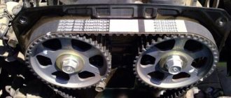
Normal braking phase
During normal braking, there is no voltage on the solenoid valves; from the master cylinder, brake fluid under pressure freely passes through the open solenoid valves and actuates the wheel brakes. The hydraulic pump is not working.
Rice. Braking phases: a) normal braking phase; b) phase of maintaining pressure at a constant level; c) pressure release phase; 1 – wheel sensor rotor; 2 – wheel sensor; 3 – wheel (working) cylinder; 4 – electrohydraulic modulator; 5 – solenoid valve; 6 – pressure accumulator; 7 – injection pump; 8 – main brake cylinder; 9 – control unit
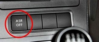
Is it possible to disable ABS on a car?
It is worth knowing that the location of the fuse box may vary. Sometimes they can be found under the hood, in other cases they end up in the cabin. Sometimes different fuses are present in the same car in different places. In this case, it is worth disconnecting through the component located in the cabin.
In addition, please note that disabling ABS may negatively affect individual components of the machine. In any case, disabling this system should be considered a temporary measure. The most accessible way to disable ABS is to pull out the corresponding fuse from the block.
A brief history of the ABS system
For the first time, the problem of wheel locking during braking became relevant in the operation of railway transport. Blocked train wheels not only wore out faster, but could also lead to a great tragedy - derailment of the train. In 1936, Bosch patented a technology to prevent wheel locking, but it was impossible to implement it due to the limited development of electronics. Real progress awaited this area in the 60-70s of the last century, when semiconductor technologies appeared. As a result, in 1970, the largest German automaker Daimler-Benz presented the first models of safe ABS . A little later, 8 years later, the first car equipped with an ABS system appeared. It became the Mercedes-Benz S-Class.
Is ABS useful?
First of all, ABS is lightning fast. Thanks to vigilant sensors, it constantly monitors the rotation speed of all wheels and immediately reacts to increased skidding. This allows you to safely navigate difficult turns, and on a straight road (also dry, with varying degrees of grip) it significantly reduces the braking distance. Some experts have calculated that a car without ABS will brake 45 m further on wet pavement than a car with ABS! In the absence of precipitation, the differences are within a few meters.
In some situations, ABS increases braking distance, for example, when there is a loose layer (snow, sand, leaves) on a surface with good grip. On a car without ABS, the locked wheels break through the loose layer and an increase in braking force occurs; if the system is working, the car remains on the layer with less grip longer.
Advantages and disadvantages of ABS
Now almost all cars are equipped with the system, which is fixed at the legislative level. This means that its advantages greatly outweigh the disadvantages with which we are continuously working.
Pros:
- ABS greatly reduces braking distances because it works much faster and more accurately than any driver on difficult surfaces;
- it remains possible to drive the car with the brake pedal fully depressed, each wheel has directional stability;
- it became possible to issue recommendations to inexperienced drivers to brake in turns and when the car loses stability; previously this was strictly prohibited;
- ABS components and modules have become the basis for the introduction of numerous electronic driver assistants that improve handling, cross-country ability and save in difficult situations.
Minuses:
- the system does not work well at low and high speeds, the algorithms continue to require improvement;
- it is very difficult to adapt ABS to work on loose soils, in mud and snow;
- complex algorithms for operating suspensions at maximum rebound strokes, associated with the wheels hanging in the air and subsequent complete release of the brakes.
ABS improvements are ongoing, many shortcomings have already been eliminated, but not on all cars. For now, they are limited to the fact that the system automatically turns off when critical situations arise. Additional difficulties are associated with all-wheel drive vehicles, but we have already learned how to deal with this.
Sensor check
It is important not only to understand what kind of ABS system this is, but also to treat it with due respect. To do this, respond to alarming “signals” in a timely manner, and not ignore them. A faulty sensor is unable to transmit a signal to the system and the automatic locking system stops working. As a result, the wheels lock during braking. In this case, the corresponding indicator on the dashboard may light up, indicating problems with ABS. And if the icon is on and does not go out, this is a serious reason to contact a car service, and as soon as possible.
Often the most common fault is a broken wire. It is easier to identify it using a tester. First you need to connect the pins to the connectors, and then measure the resistance with the device. If it is within the acceptable limits specified in the vehicle's owner's manual, then everything works.
A significant discrepancy in values indicates an obvious problem, which may have a different nature. In particular, we are talking about the desire of resistance in one direction or another:
- To zero - indicates a short circuit.
- To infinity - the presence of an open circuit in the electrical circuit.
You also need to measure the resistance when the wheel rotates - it should change, which will show the serviceability of the sensor. Detected breaks should be eliminated, and the break points should be restored only by soldering - the usual twisting is inappropriate here and will not give the desired result. Also, be careful not to reverse the polarity when connecting wires.
If the sensor is broken, you need to figure out how to remove the rear or front sensors. And here it is better to contact a car service, where everything will be done at the proper level, since all sorts of difficulties and nuances may arise.
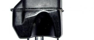
Hydraulic unit
The hydraulic unit includes:
- Electromagnetic valves, divided into inlet and outlet, are designed to regulate the pressure created in the brake cylinders of a car. The number of pairs of valves depends on the type of ABS.
- Pump (with the possibility of reverse supply) - pumps the required amount of pressure into the system, supplying brake fluid from the hydraulic accumulator, and, if necessary, taking it back.
- The hydraulic accumulator is a storage unit for brake fluid.
Elements of the anti-lock braking system
Theoretically, the ABS design looks simple and includes the following elements:
- Electronic control unit.
- Speed control sensors.
- Hydroblock.
The control unit (CU), in fact, is the “brain” of the system (computer), and what functions it performs is approximately clear, but we need to talk in more detail about the speed sensor and valve body.