Checking the ignition coil and its circuits
Misfires during engine operation can be caused not only by faulty high-voltage wires, but also by failure of the ignition module. To identify a malfunction of the ignition coil on the Lada Kalina, we will need a multimeter with which we will measure the resistance at its contacts.
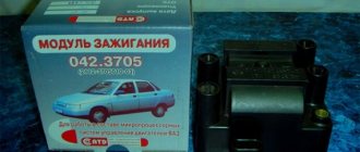
The passenger car ignition module is specially designed to improve the starting of a car engine. Since two high-voltage coils operate as the main components of the module, it is often called the “ignition coil”.
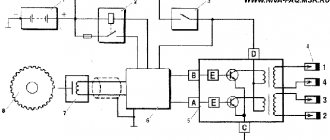
The ignition module is controlled by the ECU, which supplies constant voltage in the form of low-voltage control signals to the windings of its coils at the right moment. The end of the signal is the beginning of the spark. Thanks to magnetic induction, at the moment of application, a high voltage is generated, creating a spark at the spark plug.
If one or more cylinders in the engine do not work, acceleration failures are possible. The car will twitch and vibrate.
About an individual ignition coil
In modern cars, individual ignition coils (ICO) are used to supply a spark to the cylinder. Older cars use ignition modules, meaning one module is entirely responsible for firing all cylinders. An individual ignition coil is responsible only for the operation of one cylinder in which it is installed.
IKZ began to be installed on VAZ cars, starting with the Lada Priora car on the 126th engine. An ignition module is still installed on 8-valve VAZ engines. The car's on-board network uses low-voltage voltage, which is not capable of itself forming a powerful spark necessary for engine operation. Therefore, ignition coils are used to supply high voltage voltage.
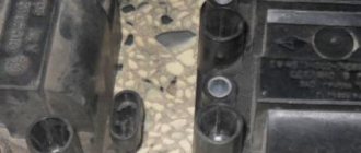
Check if the winding is shorted to ground
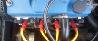
Note! By the way, when you disconnect the high-voltage wires, then also disconnect the wiring block from the module; for clarity, in the photo above it is indicated by a red arrow, and it is very easy to disconnect, just press the latch that secures it and then you can disconnect the block!
Often the reason for many calls to the service station is not so much malfunctions in the high-voltage wires, but rather the incorrect operation of the Kalina ignition module. To carry out diagnostics, you can go to a service center or pick up the tools yourself. One such is a multimeter used to measure the actual resistance level on the 8-cell pins. engine. The ignition module of a modern car performs the function of generating high voltage to produce a spark at the spark plugs. It consists of two coils with a closed magnetic circuit and a two-channel switch. Sometimes the switch is made as a separate device, but in most cases it is combined with an electronic control unit for the engine.
Situation: the next day after refueling at a network gas station with the letter “G”, eight-valve engine 21114...
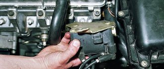
How to remove the ignition with your own hands?
It is better to check the functionality with the device removed. On an 8-cl engine, the ignition module is located in the front of the car.
Location of module 8 cells
On an engine with 16 cells there are 4 modules and they are located in a different place.
The device removal procedure consists of the following steps:
- First of all, you need to de-energize the car by removing the negative terminal from the battery.
- If the engine has protection, it must be removed.
- Next, press the latch and disconnect the wire block from the unit.
- Then we disconnect the four high-voltage wires and put them aside so that they do not interfere.
- Next, using a key set to “13” you need to unscrew the fastenings of the module to the motor.
- Use a hex screwdriver to unscrew the mounting bolts and remove the device from the engine.
Depending on the tester’s performance, the issue of replacing the device or repairing it is decided. Before installing the module in its original location, its mounts and the engine housing mounts should be cleaned, which will improve the transmitted voltage across the ground. After installation, it is necessary to check the functionality of the engine ignition system.
In order not to make a mistake when connecting high-voltage wires, you need to check the numbers on the block with the numbers on the wires; they must match. You should buy a new module with the same markings that were on the old one. To do this, you need to remember it when removing it. Then there will be no problems when installing a new device.
Regardless of which engine is installed on the car - 16 cl or 8 cl, checking the coils is the same. If you know how to check the coils of an 8-valve engine, you can check a 16-valve engine. This knowledge will help you save on visiting a car service center.
Ignition module: check and signs of malfunction
The exception is diesel engines. In them, ignition occurs due to high air compression. However, in cars with a gasoline engine, of which the majority are on the road, the ignition coil often fails. Signs of a malfunction may vary.
The video is aimed more at car owners rather than mechanics. A simple life hack is inherently flawed...
A break in the gas distribution pump drive is possible due to a jammed water pump. It is recommended to replace the water pump assembly. To prevent the vehicle from overheating, you should periodically check the operation of the pump. At the first signs of pump failure (extraneous noise, coolant leakage), you should immediately check its functionality.
Engine trouble is a very common problem in fuel-injected cars, one of the reasons for this is...
Worn tie rod ball joint is a common cause of steering failure. At the same time, a crunching sound is heard. The problem is due to a small amount of lubricant. In this case, the CV joint must be replaced.
If the ignition module is faulty, try repairing it yourself. If the MZ turns out to be in good order, the cause of the engine malfunction may be in the high-voltage wires (check) or spark plugs (check). Let us remind you that we previously told you how you can improve the ignition spark.
Contact-transistor ignition system
In order to optimize the circuit, the developers added a transistor switch to the design, which is installed in the primary winding. It is controlled using breaker contacts.
The circuit diagram is shown below.
The peculiarity of the system is that the use of an additional device made it possible to reduce the current in the circuit and extend the life of the contact group of the breaker (it began to burn less).
The contact-transistor circuit, thanks to minor changes, has received better characteristics when compared with the classic ignition option. Due to the use of a transistor, a new node was added to the system - a switch.
The advantage of the transistor in this circuit is that even a small current directed to the control (to the base) is enough to control a larger current.
As already noted, the new contact-transistor type system has slight differences from the previous version of the system. Its peculiarity lies in the special characteristics that the standard contact circuit cannot boast of.
The main difference is that the chopper interacts directly with the transistor, rather than with the bobbin. Otherwise, the operation of the contact-transit system is similar.
As soon as the current in the primary winding is interrupted, a high voltage pulse occurs in the second circuit.
If you do not pay attention to the design features and principles of connecting the switch, you can highlight one main advantage - the ability to increase the primary current thanks to the use of a transistor.
At the same time, it is possible to solve a number of problems:
- Increase the gap between the spark plug electrodes;
- Raise secondary voltage;
- Eliminate problems with starting at low temperatures;
- Optimize the spark formation process;
- Increase engine speed and power.
Another feature of the contact-transistor circuit is the need to use a coil with a separate primary and secondary winding.
The considered changes to the circuit made it possible to reduce the load on the contact group of the breaker and reduce the current passing through it. As a result, contacts last longer and system reliability increases.
Despite the considered advantages, one cannot fail to note a number of disadvantages of the contact-transistor system, which are associated with the operation of the breaker.
Thus, a spark is formed in the circuit at the moment when the current in the “bobbin” is interrupted. The current that enters the transistor is of sufficient magnitude to affect the operation of the part.
In addition, a decrease in current at the breaker contact group negatively affects certain system characteristics.
how to check the ignition module viburnum
The video is aimed more at car owners rather than mechanics. A simple lifehack to identify a faulty ignition coil like...
HOW TO FIND A FAULTY COIL AND CHECK IT. WE COMPARE NEW AND OLD COIL FOR VAZ 2110, 2111, 2112, LADA PRIORA, LADA KALINA. DECREASED DI..
During operation, you have to face various problems in the operation of the engine. If the engine starts to run unstably or the traction is lost, the ignition module (MZ or coil) may be faulty.
The reason for the engine tripping on an 8-valve Kalina when starting the engine. Moreover, after 1-2 seconds after starting, the engine worked without interruption..
The spark plugs are fresh, they have traveled no more than two thousand kilometers, the high-voltage wires were replaced after the malfunction occurred, but did not affect the picture. \nDiagnostics showed a whole bunch of errors: \n— P0343 — Camshaft position sensor, high signal level. But the timing marks are set correctly! \n— P1617 — Rough road sensor, high signal level.
Operating principle of the ignition module
It all started when, on the way home from work, for no apparent reason, the engine started to misfire and stopped pulling. Before this, a check light came on on the dashboard, after blinking several times. The problem was solved by stopping and restarting the engine. A few days later the same thing happened again. I decided to diagnose the car.
Operating a car with such a breakdown is possible (you can drive to a garage or car service station), but it is not advisable unless absolutely necessary.
Despite the high reliability and durability of the ignition module, during operation it can fail, like any other mechanism.
How to diagnose the ignition coil on a VAZ-2114
Diagnostics is carried out in several stages. First of all, the winding is shorted to ground. The multimeter must be set to check the resistance so that it works like an ohmmeter.
Experts note the main symptom of a faulty ignition coil is the absence of an igniting spark on the spark plugs.
Car enthusiasts have repeatedly tried to modify the car's transmission. For example, in tuning the VAZ 2109 brand, the transmission played an important role.
Some gasoline engines that are installed on modern domestic and imported cars are equipped with ignition modules, which are a pulsed high-voltage current source.
The peculiarity of the device is that it uses a spark distribution method, which is called the “idle” spark method. The cylinders are divided into pairs. A spark is produced in each cylinder of the cylinders.
High fuel consumption. Since one cylinder is not working, the remaining three (or more depending on the engine design) take on the entire load. Accordingly, in order to resume the previous power, the motor will require more energy.
Transformers are controlled by a controller using powerful transistor valves. It receives a reference signal from the crankshaft position sensor, on the basis of which the firing sequence of the coils in the block is calculated.
The low cost of the Lada Kalina-1 car determines the rapid wear of spare parts. However, repairing, for example, a VAZ 2109 gearbox with your own hands is quite simple, since parts are much easier to find than for other cars.
In this case, you will need to carry out a different sequence of actions. And below I will try to describe this procedure in more detail:
- It is necessary to connect the device wires to the module contacts, which are located at the edges. That is, to the extreme left and right. You can take a closer look at the photo below.
With new spark plugs, the engine began to run more stable, but after a few days the misfire error popped up again. After some more searching on the Internet, I decided to check the ignition coil and armored wires. You can find out how to do this from the car’s operating instructions; there are detailed instructions there, so I won’t give them here.
Also note that if the car does not start at all, this is not a sign of a coil failure. The fact is that there are several of them in the engine. Usually each cylinder has its own coil. On older ones, voltage is generated on two cylinders at once. Therefore, the motor will work until the last minute. If the car does not start at all, all the coils could fail at once. However, this is unlikely.
Floating speed: The situation when the idle speed of a running engine without any action taken by the driver begins to change spontaneously is called “floating speed”. Moreover, they can vary their performance so much that the engine sometimes stalls.
The weak point of the ignition coils and modules is the secondary winding, which generates a high voltage pulse. A coil break or breakdown may occur in it. The following factors lead to this phenomenon:
- use of low-quality or unsuitable candles;
- operation with non-functioning high voltage wires;
- frequent attempts to check the spark.
Device
It is no secret that the contact ignition system consists of many different elements:
- battery;
- Mechanical breaker and distributor. The first gives a low voltage current, and the second - a high voltage;
- Lock, coil and spark plugs;
- There are two types of ignition timing regulators - centrifugal and vacuum;
- High voltage wires.
Let's look at the main elements in detail:
- A breaker is a unit that provides short-term separation of the current chain in the low voltage winding. At the moment of rupture, a high voltage is formed in the secondary circuit.
- A capacitor is a part whose purpose is to prevent contacts in the breaker circuit from burning. The container is installed parallel to the contact group, which allows the product to absorb a larger amount of energy. An additional function of the capacitor is to increase the voltage on the secondary winding.
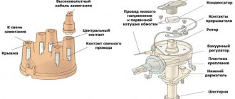
- The distributor is an element of the contact ignition system, which ensures the distribution of voltage potential to each of the cylinder spark plugs. Structurally, the device consists of a cover and a rotor. There are contacts in the upper part, and the potential from the coil is directed to the central contact, and through the side contacts to the spark plugs.
- The ignition coil is a device that converts voltage (from low to high). The part is located in the engine compartment, as are most of the elements of the contact ignition system. Structurally, the product has two windings. One is low voltage and the other is high voltage.
- Distributor - is a device in which a breaker and a distributor are located together, operating from the engine crankshaft.
- Centrifugal regulator is a unit that provides a change in the ignition timing. This parameter represents the crankshaft rotation angle at which voltage is applied to the spark plugs. To ensure complete combustion of the combustible mixture, the angle in question is set ahead of time.
Structurally, the regulator is a pair of weights that act on a plate with breaker cams placed on it. It is worth noting here that the plate moves freely, but the advance angle is set due to the position of the motor distributor.
- A vacuum-type regulator is a device that provides a change in the advance angle while adjusting the level of load on the engine (changes when you press the gas pedal). The regulator is combined with the cavity of the throttle assembly and adjusts the angle taking into account the level of vacuum.
- Spark plugs are standard ignition elements that convert energy into a spark necessary to ignite the fuel mixture in the engine cylinders. At the moment the impulse is transmitted to the spark plugs, a spark is formed, igniting the combustible mixture.
- High-voltage wires (armored wires) are an invariable element of the contact ignition system, with the help of which high voltage is transmitted along the path “coil - distributor - spark plugs”. Structurally, the product is a flexible conductor of large cross-section with one copper core and multilayer insulation.
How to check the ignition module
Ignition of gasoline in the cylinders of an internal combustion engine occurs using a spark generated by the ignition system. The ignition module is the main element of the system, creating a spark on the spark plugs using high voltage. Each car manufacturer develops and produces its own original module, but the principle of its operation is the same for all devices. During operation, deviation from the specified parameters or breakdown of the ignition module negatively affects engine operation until the power unit fails.
Types of ignition systems
In the modern automotive industry, ignition systems are classified depending on the method of controlling the process. There are three main types of schemes:
- contact (contact-transistor);
- contactless (transistor);
- electronic (microprocessor).
Characteristic features of the contact system
Historically, the contact system was one of the first and today it can only be found on older car models. In such designs, the formation of high voltage occurs in a transformer coil, and its distribution to the spark plugs is carried out mechanically - by closing and opening the circuit contacts with a breaker-distributor.
Contact ignition system device
In addition to the main elements, such systems include a centrifugal ignition timing regulator, which is necessary to convert the ignition timing relative to the crankshaft speed. It consists of two weights acting on a mobile plate in contact with the cam mechanism of the breaker.
Ignition timing is a certain position of the crankshaft at which high voltage is supplied to the spark plugs. In this mode, ignition occurs until the piston reaches top dead center, which ensures the most efficient combustion of the air-fuel mixture.
Also in the contact circuits, a vacuum ignition timing regulator is used, which changes the timing angle according to the operating mode (load) of the engine. It is connected to the cavity located behind the throttle valve, and when you press the gas pedal, it changes the advance angle depending on the magnitude of the vacuum.
When the contacts are closed, a low voltage is applied to the primary winding of the coil, where energy is accumulated and at the moment the contact opens, a high voltage is formed on the secondary winding. The energy then goes to the ignition distributor and then to the corresponding spark plug.
If the load on the power unit increases, the rotation speed of the chopper-distributor shaft increases, and the weights of the centrifugal regulator diverge, changing the position of the plate. This promotes earlier opening of contacts, which increases the advance angle. When the load on the engine decreases, the reverse process occurs.
What are the differences between a contact-transistor ignition system?
The next generation of the ignition system was a contact-transistor one, which involved installing a transistor switch coil in the primary circuit. It allows you to reduce the current in the low voltage winding, which increases the service life of the contacts.
Contact-transistor ignition system
Due to the installation of a transistor, the voltage supplied to the spark plugs is 30% greater than in a classic contact system. The gap between the electrodes and, as a consequence, the length of the spark is also larger, which means that the contact area with the air-fuel mixture also increases, which contributes to its complete combustion. In a contact-transistor ignition system, the breaker acts not on the coil, but on the switch.
When you turn the key, two types of currents begin to pass through the transistor:
- management;
- main current of the primary winding.
When the contacts open, the control circuit current disappears and the transistor turns off, preventing primary current from flowing. At this moment, the magnetic field forms a high voltage on the secondary winding. To speed up the turn-off of the transistor, a pulse transformer can be installed in a contact ignition system of this type.
Operating principle of the contactless system
An evolutionary continuation of the transistor-contact system is contactless ignition. In such designs, a special pulse sensor is installed instead of a breaker. This makes it possible to increase the service life of the ignition system due to the absence of malfunctions associated with the breaker contacts.
The sensor generates low voltage electrical pulses. It comes in three types:
- Hall Sensor. The design of such a sensor includes a permanent magnet and a semiconductor wafer equipped with a microcircuit.
- Inductive. The principle of its operation is based on changing the induction value of the sensing element depending on the size of the gap between the sensor and a moving plate rotor acting on the magnetic field.
- Optic. It consists of an LED, a phototransistor and a matching chip. When light from the diode hits the phototransistor, the sensor supplies ground (minus power) to the switch. Blocking the flow of light provokes the disappearance of the current in the coil and contributes to the further formation of a spark.
Structurally, the pulse sensor is integrated into the distributor and is regulated by the engine crankshaft rotation mode. Interruption of the current in the primary winding of the ignition coil of the contactless system is also carried out by a transistor switch, but responding to sensor signals.
When the crankshaft rotates, the sensor sends voltage pulses to the switch. The latter, accordingly, generates current pulses in the low voltage winding of the coil. When no current flows, a high voltage appears on the secondary winding, which is transmitted to the distributor and then through high-voltage wires to the desired spark plug. Changing the advance angle in a contactless ignition system is also performed by centrifugal and vacuum regulators.
Purpose and principle of operation
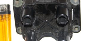
Ignition module VAZ 2110
The ignition module of a modern car performs the function of generating high voltage to produce a spark at the spark plugs. It consists of two coils with a closed magnetic circuit and a two-channel switch. Sometimes the switch is made as a separate device, but in most cases it is combined with an electronic control unit for the engine. Externally, the modules differ in the number of wires in the connection connector: a module with a switch has 4 wires, and paired coils have 3.
The ignition module is controlled by the ECU, which supplies constant voltage in the form of low-voltage control signals to the windings of its coils at the right moment. The end of the signal is the beginning of the spark. Thanks to magnetic induction, at the moment of application, a high voltage is generated, creating a spark at the spark plug. The device is located in the engine compartment and can be easily identified by the high-voltage wires leading to the spark plugs.
General operating principle
The presence of a contact ignition system in a car means that the ignition of the fuel in the cylinders is carried out upon the appearance of a spark from the spark plug.
In this case, the spark itself occurs when a high voltage pulse arrives from the ignition coil.
The key function is performed by the ignition coil, which, according to its operating principle, resembles a transformer.
It consists of two windings (primary and secondary) wound on a metal core.
First, voltage is applied to the primary winding, after which a current is created in the coil.
As soon as a short-term break in the primary circuit occurs, the magnetic field is leveled, but a high voltage (about 25,000 Volts) appears in the secondary winding.
At this moment, a voltage of 300 Volts is also present on the primary winding.
The reason for its appearance is self-induction currents. It is because of the appearance of this current that the breaker contacts burn and spark.
From the above we can conclude that the secondary voltage directly depends on the following aspects:
- Magnetic field;
- The intensity level of the current drop in the primary winding.
To increase the secondary voltage and reduce the risk of burning the contact group, a capacitor is included in the circuit (installed in parallel). Even with a slight opening, the capacitor is charged.
A schematic diagram of the contact ignition system is shown below.
The capacitance discharge occurs through the primary winding, through the formation of a reverse voltage pulse current. Thanks to this feature, the magnetic field disappears and the secondary voltage increases.
The optimal capacitor capacity for a contact ignition system is 0.17-0.35 µF. For example, domestically produced Zhiguli cars have a capacitor with a capacitance of 0.2-0.25 μF (at a frequency of 50 to 1000 Hz).
If the vehicle's ignition system operates without failure, the secondary voltage should constantly increase. It depends on two main parameters - the size of the gap between the spark plug electrodes, as well as the pressure in the cylinders of the machine.
For a contact ignition system, this parameter (secondary voltage) should be at the level of 8-12 Volts.
In order for the system to operate without failures, at the moment of interruption the mentioned indicator increases to 16-25 kV. The presence of such a reserve allows you to avoid adverse consequences from certain fluctuations in the ignition system.
The problems mentioned above include adjustments to the composition of the combustible mixture or changes in the distance between the spark plug electrodes.
For example, a decrease in the oxygen level in the fuel-combustible mixture leads to an increase in voltage to 20 kV.
Despite a number of measures taken, the creators of the contact ignition system were unable to completely avoid burning the contact group. The optimal way to reduce this effect is to strictly maintain the gap at a minimum level (0.3-0.4 mm).
As an example, we can cite domestic VAZ cars, in which the gap in the breaker is 0.35-0.45 mm, which corresponds to an angle of 52-58 degrees Celsius (provided that the contact group is in a closed state).
If this angle changes, the voltage in the secondary winding is also adjusted. As a result, sparks appear not only on the contacts, but also on the sliders. For this reason, the quality of the spark decreases and the engine loses power.
The reliability of the contact ignition system, which depends on a number of factors, deserves special attention:
- Shape, energy and time of spark appearance;
- The number of sparks in a certain area;
- Secondary voltage (one of the most important characteristics). The larger this parameter, the less dependent the system is on the composition of the combustible mixture and the level of cleanliness of the electrodes.
Signs of a malfunctioning ignition module
Checking the ignition module with a removed spark plug
A malfunction of the ignition module is determined by the following symptoms:
- Difficulty starting a cold engine due to lack of spark on one or more spark plugs.
- Floating engine speed at idle is a situation in which the speed changes without any action on the part of the driver.
- Dips in power, which manifests itself during acceleration and driving up a long climb.
- Decrease in engine power.
- Cylinders 1-4 or 2-3 do not work (engine “troits”).
- Indication of the “Check Engine” indicator.
Symptoms of a bad coil
There are many symptoms of coil failure and sometimes it is very difficult to determine that the coil is to blame. If such symptoms appear in your car, then you should pay attention to the ICD.
Signs of coil failure:
- One of the cylinders does not work;
- The car does not develop power;
- Jerking when pressing the gas pedal sharply;
- The engine shakes at idle;
- Increased vibration at idle;
- Floating speed;
It should also be noted that if the ignition coil is faulty, misfires will appear in the cylinders, as a result of which the ECU will turn off the operation of the faulty cylinder and signal this by turning on the “Cheek Engine” lamp. When “Cheek Engine” appears on the car, it is necessary to diagnose the system. If there are misfires, the ECU will display errors 0301, 0302, 0303, 0304. Where the last digits of the codes are the cylinder number.
It is not recommended to operate a car with a faulty ignition coil; this can lead to failure of the catalyst.
Possible causes of ignition module malfunction
Despite the high reliability and durability of the ignition module, during operation it can fail, like any other mechanism. Among all possible causes of breakdowns, in 9 out of 10 cases the following occur and are diagnosed:
- Use of inappropriate components in the ignition system. High-voltage wires are selected based on the parameters of the module, since excessively high or low voltage creates malfunctions or burns out contacts.
- Defective or damaged parts, poor quality assembly. Defective components break down faster and damage other components or elements of the system. Practice shows that the selection of high-quality components and their periodic diagnostics allow the module to remain operational for a long time.
Checking the ignition module
Checking the ignition module for functionality is carried out in the following ways:
Replacing the ignition module with a known good one
1. The easiest way is to connect a known working module. In this case, the devices must be completely identical, the high-voltage wires are in good condition, and the reliability of the contacts has been checked.
Checking the contacts on the ignition module
2. Moving the module, which allows you to identify unreliable contacts. To do this, move the wire block and the module itself. If during exposure the engine reacts by changing its operation, then the cause of the problem lies in poor contact.
Measuring resistance at the terminals of the ignition module
3. Resistance measurement. To do this, you will need a tester switched to ohmmeter mode. Measurements are carried out on the paired terminals of the module between cylinders 1 and 4, as well as cylinders 2 and 3. The resistance value should be the same and approach 5.4 kOhm.
Checking the ignition module using a tester
4. Check the voltage with a tester. One probe of the device is applied to contact A of the block, the second to ground. After turning on the ignition, take readings from the device. If the wire is in good condition, it will show a voltage of 12 V; if it is missing, check the fuse protecting the ignition module. Then check the continuity of the circuit with a 12 V test lamp. Apply one end of the wire to contact A and rotate the starter. If the lamp does not blink, the circuit is broken. The procedure is repeated in a similar way with other contacts.
Diagnostics of the ignition module with professional equipment
5. Diagnostics at a service station by connecting a computer with special software to the computer. Malfunctions are detected in the form of errors indicated by an alphanumeric code, after which a more in-depth diagnosis of the malfunction is carried out to make a decision - repair the ignition module or replace it. A similar check is carried out at a specialized service station using an oscilloscope.
General information
The purpose of the Kalina ZZ is no different from other cars - turning on the ignition and controlling the engine starter. It is equipped with a mechanical interlock and protection against restarting the starter without turning off the ignition. This allows you to protect the flywheel crown and bendix from accidental turning of the key. There is also electronic protection in the form of an immobilizer, the antenna of which is integrated into the 3Z.
The Kalina ignition switch has 3 positions, each of which is described in the table.
Side lights, radio, hazard warning lights, brake lights, courtesy lamp
Car ignition system, low and high beams, heater, washer and wipers, turn signals, fuel pump.
The key can only be pulled out in the zero position. In order not to forget it in the lock, when the engine is turned off, an audible alarm is provided, which turns on simultaneously with the opening of the driver's door.
Repair
Ignition module VAZ 2107
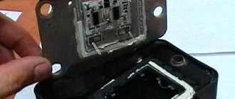
The design of the ignition module is quite complex: it includes one or more coils, a board, contacts and wires. Of all the above elements, only contact connections can be repaired; in some cases, replacement of parts (transistors, coils) is possible.
The module is dismantled and opened for repair purposes. For this you will need:
- Socket wrenches with heads 1, 13 and 17.
- Hexagon 5.
- Screwdriver.
- Soldering iron.
- Flux for aluminum.
- Stranded wire.
- Nail polish.
Opening the ignition module
Repair of the ignition module is carried out in the following order:
- On the removed device, open the case by prying it off with a screwdriver.
- Remove the silicone film covering the board.
- All aluminum is removed from the explosive contacts.
- On the board, new wires are soldered in place of all the dismantled old ones. To do this, the surface of the collector is cleaned of deposits, after which the board is heated to 180 o C (a characteristic smell will indicate when the desired temperature has been reached). During the soldering process, the ends of the wires are connected to the module.
- At the end of the operation, all contacts, the board and the module are covered with nail polish.
- The device is assembled in the reverse order, installed on the car and the engine is started. In case of normal operation, the ignition module is sealed tightly with sealant, while the wires are tucked inside the cavity so that they are not pinched at the edges by the plate.
If the device does not work, then a breakdown inside the module should be looked for more carefully. The transistor, electronic component may have failed, or there may be a break in the coil. Such a repair makes sense only if its price is significantly lower than the cost of a new part.
Repair or buy a new one
There is no clear answer to this question. The fact is that it is very difficult to find a new contact group on the Kalina ZZ, in contrast to the classics, Samara and the tenth family. Therefore, you have to repair it, which without experience, skills and desire is not the best idea. Most often, owners install a new ZZ by purchasing it assembled.
In this case, it is necessary to take into account that the Kalina ignition switch has an immobilizer that will not respond to the new key and the car will not be able to start. Of course there is a way out. You can retrain the immobilizer for a new key. In this case, you will also have to change the cylinders on the door locks.
You can do it easier - carry two keys with you. True, it is not clear whether it is worth keeping them on one bundle. Therefore, the most reasonable thing would be to make a new “tip” and install it on the old key. By the way, it may be included in the delivery of a new lock.
Purpose and principle of operation
Ignition module VAZ 2110
The ignition module of a modern car performs the function of generating high voltage to produce a spark at the spark plugs. It consists of two coils with a closed magnetic circuit and a two-channel switch. Sometimes the switch is made as a separate device, but in most cases it is combined with an electronic control unit for the engine. Externally, the modules differ in the number of wires in the connection connector: a module with a switch has 4 wires, and paired coils have 3.
The ignition module is controlled by the ECU, which supplies constant voltage in the form of low-voltage control signals to the windings of its coils at the right moment. The end of the signal is the beginning of the spark. Thanks to magnetic induction, at the moment of application, a high voltage is generated, creating a spark at the spark plug. The device is located in the engine compartment and can be easily identified by the high-voltage wires leading to the spark plugs.
Where is it used?
Past and present owners of VAZ “classics”, who understand the design of such cars, are well aware of the weak points and operating principles of the contact-type ignition circuit.
Its peculiarity lies in the distribution of voltage to the combustion chambers of the engine through contact connections (hence the name).
Modern cars are equipped with more modern (electronic) ignition, which is controlled by a microprocessor.
The main systems operating on the contact principle include:
- KS3 (KSZ) is the most common type of circuit, the structure of which contains a distributor, a coil and a breaker.
- KTS3 (HKZ-2, JFU4, HKZk) - ignition system with a contact sensor and preliminary energy storage.
- KTC3 (TSZi) is another type of system that operates on the contact principle. It contains a transistor and contacts, as well as an inductive energy storage device.
Selected aspects of technical operation
Many inexperienced drivers, not understanding the essence of the breakdown, decide that an expensive replacement of the ignition switch or the wiring as a whole is necessary. Experienced drivers advise not to rush to conclusions. If, due to various circumstances, the ignition coil fails, the corresponding indicator lights up on the dashboard. The first thing the driver should do in such a situation is to drive the car into the garage and open the hood.
Often spark plugs fail due to a power surge or short circuit. As a result, the spark does not travel properly throughout the system. A number of other circumstances can cause a similar problem:
- the car was damaged in an accident;
- replacement of spark plugs may be required after lightning strikes the car;
- poor-quality previous repairs;
- use of non-original spare parts;
- failure to comply with technical inspection deadlines at the service center.
Often the reason for many calls to the service station is not so much malfunctions in the high-voltage wires, but rather the incorrect operation of the Kalina ignition module. To carry out diagnostics, you can go to a service center or pick up the tools yourself. One of these is a multimeter used to measure the actual resistance level on the 8-cell pins. engine. To obtain correct measurement results, it is necessary to carry out 2 times.
The ignition system can be damaged in any part of the circuit, so monitoring must be careful. It all starts with checking that the winding is properly connected to ground. It is necessary to carefully insert the contacts, focusing on the indicators of the device. Then one of the contact terminals of the device is connected to the central contact of the spark plug coil. In this case, the second contact is attached to ground.
Replacing the ignition switch
As always, if the work involves electricity, you need to start by disconnecting the negative terminal of the battery. The tool you will need is a shaped screwdriver and a small chisel. You must purchase an ignition switch in advance. In this case, you need to take into account the presence of an immobilizer. If everything is ready, you can proceed to replacement. The sequence of actions is as follows:
- After unscrewing the five bolts, remove the decorative steering column cover. The screws are different, so it’s better to remember which one was placed where. In addition, to remove the casing, you need to lower the steering column adjustment knob.
- The ignition switch is secured to two clamps, secured with bolts that cannot be unscrewed with a key. Therefore, you will have to use a chisel. You need to rest it against the cap and unscrew it with careful but rather strong blows until it becomes possible to do it with your hands. That is, you should not cut off the bolt with a chisel, but use it as an analogue of a key.
- Thus, you will have to unscrew all 4 screws.
- The lock will remain hanging on the wires.
- We disconnect the electrical connectors, and the ignition switch can be easily removed.
- Installation is carried out in reverse order.
Signs of a malfunctioning ignition module
Checking the ignition module with a removed spark plug
A malfunction of the ignition module is determined by the following symptoms:
- Difficulty starting a cold engine due to lack of spark on one or more spark plugs.
- Floating engine speed at idle is a situation in which the speed changes without any action on the part of the driver.
- Dips in power, which manifests itself during acceleration and driving up a long climb.
- Decrease in engine power.
- Cylinders 1-4 or 2-3 do not work (engine “troits”).
- Indication of the “Check Engine” indicator.
Despite the high reliability and durability of the ignition module, during operation it can fail, like any other mechanism. Among all possible causes of breakdowns, in 9 out of 10 cases the following occur and are diagnosed:
- Use of inappropriate components in the ignition system. High-voltage wires are selected based on the parameters of the module, since excessively high or low voltage creates malfunctions or burns out contacts.
- Defective or damaged parts, poor quality assembly. Defective components break down faster and damage other components or elements of the system. Practice shows that the selection of high-quality components and their periodic diagnostics allow the module to remain operational for a long time.
Checking the ignition module
Replacing the ignition module with a known good one
1. The easiest way is to connect a known working module. In this case, the devices must be completely identical, the high-voltage wires are in good condition, and the reliability of the contacts has been checked.
Checking the contacts on the ignition module
2. Moving the module, which allows you to identify unreliable contacts. To do this, move the wire block and the module itself. If during exposure the engine reacts by changing its operation, then the cause of the problem lies in poor contact.
Measuring resistance at the terminals of the ignition module
3. Resistance measurement. To do this, you will need a tester switched to ohmmeter mode. Measurements are carried out on the paired terminals of the module between cylinders 1 and 4, as well as cylinders 2 and 3. The resistance value should be the same and approach 5.4 kOhm.
Checking the ignition module using a tester
4. Check the voltage with a tester. One probe of the device is applied to contact A of the block, the second to ground. After turning on the ignition, take readings from the device. If the wire is in good condition, it will show a voltage of 12 V; if it is missing, check the fuse protecting the ignition module. Then check the continuity of the circuit with a 12 V test lamp.
Diagnostics of the ignition module with professional equipment
5. Diagnostics at a service station by connecting a computer with special software to the computer. Malfunctions are detected in the form of errors indicated by an alphanumeric code, after which a more in-depth diagnosis of the malfunction is carried out to make a decision - repair the ignition module or replace it. A similar check is carried out at a specialized service station using an oscilloscope.
Pinout of lock VAZ-2108, VAZ-2109, VAZ-21099
Pinout according to the old type
Pinout of the VAZ-2109 ignition switch with unloading relay:
- comes +12V in position I, II, III (parking)
- comes +12V in position I, II, III (parking)
- comes +12V in position III (parking)
- position I, +12V goes out after turning on the ignition (contact 15/2), disappears at start (II);
- position I, +12V goes to the starter (pin 50);
- position I, +12V goes away after turning on the ignition (pin 15), does not disappear when starting II;
- +12V comes from the battery (pin 30);
- comes +12V constantly.
New pinout type
Pinout of the new VAZ-2109 ignition switch:
- comes +12V constantly
- comes +12V constantly
- +12V arrives after turning on the ignition (pin 15), does not disappear when starting II;
- +12V arrives after turning on the ignition (contact 15/2), disappears at start (II);
- position I, +12V goes to the starter (pin 50);
- +12V arrives after turning on the ignition (pin 15), does not disappear when starting II;
- +12V comes from the battery (pin 30);
- comes +12V constantly.