Sometimes, when repairing their car, drivers have to dismantle high-voltage wires (otherwise known as armored wires). At the same time, not all motorists realize to remember or write down the correct order of connecting these wires, as a result of which the repaired car may simply not start. We will talk about the order of the cylinders of the VAZ 2114 and in what sequence the armored wires should be connected to them in today’s article.
Ignition in a VAZ 2114
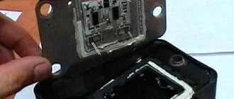
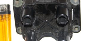
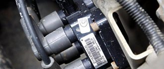
IGNITION MODULE DEVICE FOR VAZ 2115
This module consists of two high-voltage transformers and two control units (electronic), enclosed in a durable plastic case with four outputs of high-voltage wires. Electronic control units are also commonly called ignition coils, and one of them - “working” - is connected to the spark plugs of the first and fourth cylinders of the power unit, the other - “idle” - with the spark plugs of the second and third.
This type of connection, made using high-voltage wires, ensures synchronous “slippage” of the spark pulse in the cylinders of the power plant.
Thus, we can formulate the functional purpose of the ignition module - generating high-voltage spark pulses on the spark plugs of the vehicle's power unit.
The VAZ 2115 ignition module is controlled by a controller whose operating functions include processing data received from vehicle system sensors: coolant temperature, rotation speed and position of the crankshaft, air flow, presence of detonation, etc.
Numbering of cylinders on different types of engines
As such, there is no strict international system for the location and numbering of engine cylinders. And that's bad. Therefore, before you begin any type of repair of the engine or ignition system, immerse yourself in the Operating and Repair Instructions for your particular car.
Rear-wheel drive 4- and 6-row engines in the USA have a master cylinder number 1 from the radiator, the remaining cylinders are numbered towards the passenger compartment. But there is also reverse numbering, when the master cylinder is considered to be the one closest to the passenger compartment.
For French engines, cylinder numbering occurs on the gearbox side. And the numbering of the cylinders of V-shaped engines comes from the right side, i.e. on the torque side.
Front-wheel drive cars typically have a transversely mounted engine. Here the cylinders are numbered on one side, and cylinder No. 1 is located on the passenger side.
V-twin multi-cylinder engines have the driver's side master cylinder in the bank closest to the passenger compartment. Then there are the odd-numbered engine cylinders, and on the opposite side (closer to the radiator) there are the even-numbered ones.
Therefore, in order to ensure that you are not completely confused due to the lack of a unified international standard for the location and numbering of engine cylinders, use the manufacturer’s Operating Manual.
Good luck learning the numbering and arrangement of engine cylinders.
Many motorists, especially beginners who have just purchased a VAZ-2114, have wondered how the 8-valve injection engine that is installed on this car works. This article will discuss the design of the motor, its main characteristics, as well as dismantling and repair features. This information will be very useful for beginners and those who do not know how the main power unit works.
Video about the VAZ-2114 engine
Video review of the VAZ-2114 engine operation, features and characteristics.
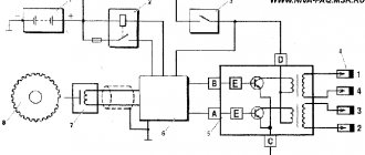
2115 IGNITION MODULE DIAGRAM
The circuit diagram and connection diagram of this electronic device is presented below.
The ignition module installed on the Lada Samara is extremely resistant to both low and high temperatures. Operating temperature range: -400/+1300C.
The only negative point in the operation of this electronic device is its complete inability to repair. However, even a novice car enthusiast can replace it on his own.
Experts consider the most common malfunctions of the Samara ignition module to be:
Purpose
The ignition module is used to generate a spark and serves as a kind of step-up transformer that raises the voltage from 12 to 40,000 volts. Such a high voltage is necessary to form a powerful spark in the combustion chamber and effectively ignite the fuel mixture.
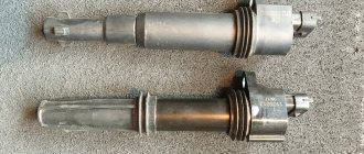
There is a Lada Super Auto car built on the basis of 2114 with a Priora engine; this engine does not have an ignition module, and instead uses an individual ignition coil, which is installed on each cylinder.
The ignition module, unlike the IKZ, is responsible for 4 cylinders at once.
HOW TO CHECK THE IGNITION MODULE
The ignition module is one of the main elements of the ignition system for the combustible mixture in the cylinders...
- Unstable operation of the power plant when accelerating the vehicle.
- Decrease in engine power.
- “Intermittent” idle speed.
- Malfunction of paired (1/4 – 2/3) engine cylinders.
Attention! The detection of the above malfunctions is not final evidence of failure of the ignition module, since similar symptoms are possible due to malfunctions of the spark plugs and unreliable connection of high-voltage wires.
What determines the numbering of engine cylinders?
However, it is important to know that whatever the engine layout and cylinder arrangement, cylinder No. 1 - the main cylinder, always contains spark plug No. 1.
Naturally, this is the order in which the cylinders of any engine are numbered. What determines the location and numbering of engine cylinders:
- drive type: front or rear;
- engine type: in-line or V-shaped;
- engine installation method: transverse or longitudinal;
- direction of motor rotation: clockwise or counterclockwise.
The arrangement of cylinders in multi-cylinder engines is as follows:
- vertically - that is, in one row, without angular deviations;
- obliquely – at an angle of 20°;
- V-shaped - in two rows. The angles between rows can be 90 or 75 degrees;
- opposite (horizontal) – the angle between the cylinders is 180°. This arrangement of cylinders is used in bus engines, which allows the engine to be placed under the floor of the passenger compartment, freeing up usable space.
HOW TO SET THE IGNITION
Ignition timing directly affects the performance of the vehicle. From the correctness of the settings...
The correct functioning of the ignition module not only has a significant impact on the start of the vehicle’s power plant, but also ensures the stability of its operation in all modes. To carry out a complete diagnosis of this electronic device, you need quite complex equipment, available only in large specialized workshops. However, you can check the functionality of the ignition module yourself in an amateur garage. The only logistical support for this test will be a multimeter, or tester.
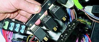
The first and simplest way to determine the functionality of the ignition module is to replace it with a known-good device.
Attention! When using a donor car for testing, do not forget that only the first Lada Samara models were equipped with the ignition module, as a separate device. Machines of later releases are equipped with separate type devices (the switch is included in the electronic control unit).
The procedure for replacing the ignition module includes the following steps:
- Preparation of the necessary tools: wrench 17 (open-end), wrench 13 (open-end), wrench 10 (socket), hexagon.
- De-energizing the vehicle by disconnecting the “-” terminal from the battery.
- Removing the wire block.
- Disconnecting high voltage wires.
- Unscrewing the fastenings to the power unit.
- Recess of the ignition module (unscrews from the holder using a hexagon).
Installing a replacement module involves connecting high-voltage wires (the module body contains hints). In addition, the wire terminals also have corresponding designations. We install the ignition module, performing the manipulations in the reverse order, followed by checking its functionality.
Should high-voltage wires be replaced and when?
No matter how well the armored wires are made, they also have a limited service life. According to current regulations, they must be replaced after every 30,000 km traveled. In practice, many motorists ignore this rule, continuing to travel with wires that have already outlived their useful life.
Such inattention can cause a whole host of problems, including:
- poor ignition;
- overclocking problems;
- engine tripping;
- inability to start the car.
Replacement of armored wires of VAZ 2114
All these troubles are caused by one single factor - an increase in the electrical resistance of the core of high-voltage wires, as a result of which it becomes “more difficult” for the impulse from the coil to reach its destination.
You can check whether you can still drive with the old wires or not - at home.
To do this you need:
- Turn off the ignition.
- Remove one of the armored wires.
- Measure its resistance using a megohmmeter or multimeter in the appropriate mode.
- If the resistance turns out to be equal to or close to the figure indicated on the wire insulation, then it is in good condition, but if it turns out to be greater, then the wire should be replaced.
- Repeat this operation on the remaining three wires.
It should be remembered that if only one of the wires is faulty, then all four should still be replaced.
Also, do not forget about the cleanliness of the contacts of high-voltage wires - they can also cause ignition problems. If oxides are noticeable on the metal tip, they should be cleaned with fine sandpaper or a cloth moistened with kerosene. By following these simple rules for caring for armored wires and replacing them, you can almost completely avoid troubles associated with the ignition system.
IGNITION MODULE VAZ-2114 - CHECKING, DISASSEMBLY AND REPLACEMENT
The ignition module (IM) plays a critical role in the performance of the vehicle. It creates momentum...
Another method involves measuring the resistance of individual module elements using a multimeter (tester). Using the tester probes, we close the “paired” terminals of the module, which provide connection to high voltage wires, and measure the resistance value.
The resistance value of a working device should be approximately 5.4 kOhm. The discrepancy between this parameter and the specified value indicates that the VAZ 2115 ignition module is inoperative.
There is another, so-called “folk” method, or the “shake-up” method. With the power plant running, lightly tap the module. Despite all the “technical non-scientific” nature of such manipulations, they are capable of producing results. True, only in the case when the contact of the elements inside the housing is broken.
Examination
It is a mistake to assume that damage to high-voltage wires does not in any way affect the condition of the module itself. Many people think of simply replacing high-voltage elements, but in reality they will still have to change the module.
This is explained by the fact that damaged or defective wires direct the wrong current, the configuration of which does not correspond to the necessary parameters. As a result, the spark hits inaccurately or ineffectively, causing the module to burn out and become unusable.
In general, the best option for checking the ignition module on a VAZ 2114 is to use an oscilloscope . But, firstly, not every driver has it, and secondly, few people can use them. Therefore, we will carry out the check using improvised means:
- 12-volt light bulb;
- Tester (available for little money at any auto parts store).
Let's start with preliminary manipulations with the accompanying elements of the ignition module.
- Check the wiring harness. It is disconnected and the voltage indicator is checked.
- To do this, fix the tester on contact A, and connect the other terminal to engine ground.
- In normal condition, the voltage reading will be 12V.
- If there is no voltage, most likely the fuse has blown.
- If everything is fine, transfer the terminals of your tester to contacts A and B, start the car. In this case, the starter should turn and the 12-volt light should blink.
- In the absence of these phenomena, we can talk about the presence of a break in circuit A of the contacts.
Next we go to the ignition module itself.
There are several ways to check the condition of your unit. Therefore, let's look at each of them.
- Set the tester to ohmmeter mode. Use it to measure the resistance on the high-voltage lines going to cylinders 1 and 4, and then, by analogy, to the wiring of cylinders 2 and 3. In normal condition, the device will give you readings from 5.2 to 5.5 ohms.
- Give the device a gentle tug. Thus, you will shake the wiring block and the module. Moreover, this must be done in the operating mode of the power unit. If the device works without obstruction when loosened, everything is fine, you are lucky. If not, you will again have to study the condition of the wiring.
Third way
The third method is considered the simplest, since it involves replacing your device with a similar one that works exactly. But to do this, you have to find a full-fledged twin. We are talking about an ignition module from a car similar to yours in terms of year of manufacture and power unit used. It’s just that 1.5-liter engines have modules, and 1.6-liter engines have coils.
But to replace a module with a module, you will have to first dismantle yours. This is done as follows:
- Remove the negative terminal from the battery, which will allow you to turn off the power to the car;
- Disconnect four high voltages from the ignition module;
- Disconnect the wire block. To do this, you need to release the special clamp that holds the block on the module;
- Next, unscrew the three nuts. With their help, the module is held on the bracket;
- There are three long pins on the bracket, from which the module can simply be pulled off.
Having dismantled your module, you can put another unit in its place, thereby verifying the functionality of that one and the malfunction of yours.
Video “The principle of operation of internal combustion engines”
This instructional video explains how the combustion system works.
Place the cylinder block in a convenient place and tighten the missing studs. Secure the generator with 2 bolts.
The crankshaft bearings and half rings, as well as the pistons and oil seals, must be lubricated with oil. When assembling the engine, the crankshaft seals must be new.
Install liners with a groove in the first, second, fourth, fifth sockets of the cylinder block, and liners without a groove in the third socket. Install the crankshaft into the main bearings and thrust half rings into the middle bearing seat.
How to connect wires correctly
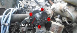
When replacing high-voltage conductors, they are first connected to the ignition distributor. The distributor cover is convenient in that it is always installed in one position. There is a special mark on it, thanks to which it will not be difficult to place the part in place. Before connecting the wires, inspect the cover. It must be intact, since if cracks appear, the performance of this unit is not guaranteed.
The mark on the distributor cover is located next to the wire socket of the first cylinder. The firing order of the cylinders is slightly out of order (1-3-4-2) due to the ignition slider. It moves around the circle (distributor) counterclockwise. It is precisely by this principle of movement of the slider that it is easy to remember the order of the wires. They need to be connected to carburetor and injection VAZ-2109 according to the same principle. On the distributor cover, connect the wires according to the principle of movement of the slider, this is the only way you can set the ignition correctly:
- the socket of the first cylinder is located at the mark;
- the third one is connected at the very bottom;
- on the same line with the socket of the first, there is a place for the wire to the 4th cylinder;
- at the top point the second cylinder is connected.
On the engine itself, the cylinder numbering goes from the location of the timing belt to the starter, that is, from left to right. The fourth cylinder is closest to the starter, and the first is closest to the timing belt. When connecting, it is important to look at which socket of the distributor cover the wire comes from, if you confuse their location, the car will not start.
If you have connected the wires correctly, but the car still does not start, then the problem may be in them. Check high-voltage conductors for integrity. If you haven't changed them in a while, it's worth buying a new set. The peculiarity of these wires is that over time microcracks can form on their surface. They lead to a lack of spark when the ignition distribution system is working. Moisture and dust get into these cracks, which damages the wire from the inside, although it appears intact from the outside.
Car enthusiasts recommend purchasing sets of high-voltage wires from foreign manufacturers, as they last much longer than stock or domestic ones. It is advisable to replace the spark plugs along with the wires, especially if cracks or carbon deposits appear on their surface. This is necessary so that after repair you definitely do not have problems with ignition.
Legend
For ease of maintenance and installation, the electrical wires in the diagrams are made in different colors, identically laid in the car, so that their purpose can be visually determined.
For brevity, colors are indicated by the first letters of the name:
- Blue – “G”;
- Brown – “K”;
- Gray – “C”;
- White – “B”;
- Orange – “O”;
- Yellow – “F”;
- Black – “H”;
- Green – “Z”;
- Pink - "R".
Thanks to the colors, it is easy to determine whether the rein belongs to a particular chain
For reference: the red wire is traditionally used to supply power from the positive terminal of the generator or battery. Therefore, in all diagrams contained in the factory instructions, it is designated by the letter “P”.
The article Wiring diagram for VAZ 21074 injector: understanding the intricacies will also be useful.
Engine diagram and structure
General view of the engine
Before we begin to consider the design of the engine and describe the characteristics, it is necessary to consider the design of the components and parts that are located directly in the main power unit and outside.
Diagram and design of the Samara-2 engine
Show schematic description
1 – generator drive pulley; 2 – oil pump; 3 – timing belt; 4 – toothed pulley of the coolant pump; 5 – front cover of the timing mechanism drive; 6 – tension roller; 7 – camshaft toothed pulley; 8 – rear cover of the camshaft drive; 9 – camshaft oil seal; 10 – cylinder head cover; 11 – camshaft; 12 – front cover of camshaft bearings; 13 – pusher; 14 – valve guide; 15 – oil separator mesh for the crankcase ventilation system; 16 – exhaust valve; 17 – inlet valve; 18 – rear cover of camshaft bearings; 19 – fuel pump; 20 – housing of auxiliary units; 21 – ignition distributor sensor; 22 – outlet pipe of the cooling jacket; 23 – cylinder head; 24 – spark plug; 25 – crankcase ventilation hose; 26 – flywheel; 27 – crankshaft rear oil seal holder; 28 – rear crankshaft oil seal; 29 – cylinder block; 30 – oil pan; 31 – oil level indicator (oil dipstick); 32 – crankshaft; 33 – piston; 34 – connecting rod cover; 35 – connecting rod; 36 – crankshaft main bearing cover; 37 – front crankshaft oil seal; 38 – crankshaft toothed pulley.
Also, it’s worth looking at a cross-section of the VAZ-2114 engine:
Cross section of the Samara engine
Show schematic description
1 – oil pan drain plug; 2 – oil pan; 3 – oil filter; 4 – coolant pump; 5 – exhaust manifold; 6 – intake manifold; 7 – carburetor; 8 – fuel pump; 9 – cylinder head cover; 10 – camshaft bearing cover; 11 – camshaft; 12 – crankcase ventilation hose; 13 – valve adjusting washer; 14 – pusher; 15 – valve cotters; 16 – valve springs; 17 – oil scraper cap; 18 – valve guide; 19 – valve; 20 – cylinder head; 21 – spark plug; 22 – piston; 23 – compression piston rings; 24 – oil scraper ring; 25 – piston pin; 26 – cylinder block; 27 – connecting rod; 28 – crankshaft; 29 – connecting rod cover; 30 – oil level indicator; 31 – oil pump receiver
Characteristics of an 8-valve engine
Many motorists remember how at the end of the 90s of the 20th century and the beginning of the 2000s, the VAZ 2108-09, which was also called “Samara,” was popular on the roads of the CIS. These cars became legendary in that era. Due to the high popularity, the AvtoVAZ plant decided to resume production of these models with some modifications.
VAZ-2114 engine under the hood
Firstly, the VAZ-2114 received a modified engine . In essence, this is an injection version of the Samara. Although it received some features from modern engines. If we consider in more detail, the Samara-2 engine (this is the type installed on the VAZ-2114) is a mixture of two engine options into one: from the VAZ 2108 and VAZ 2110.
Many motorists liked the Samara-2 power unit and fell in love with it. The main indicator was ease of repair and inexpensive spare parts. Thus, the 8-valve engine has become the standard for “price-quality” indicator.
When the basic information has been reviewed, you can proceed directly to considering the characteristics of the motor.
Table of main characteristics of the Samara-2 engine 8 valves:
| Name | Characteristic |
| engine's type | In-line, longitudinal type, 4-cylinder, 8-valves |
| Fuel type | Gasoline (installation of gas equipment is possible) |
| Cylinder arrangement | 1-4-3-2 |
| Injection system | Distribution, injection type |
| Control | Bosch, "January" or GM |
| Camshaft location | Upper |
| Drive unit | Front |
| Piston and ring diameter | 82 – nominal (tolerances by group: A – 82.00-82.01, B – 82.01-82.02, C – 82.02-82.03, D – 82.03-82.04, E – 82.04-82.05) |
| Crankshaft | Cast iron |
| Cylinder block | Cast iron |
| Timing system | Belt and roller |
Disassembly and repair: basic facts
Let's consider this paragraph of the article as reference information, because if we talk about engine repair, then each individual component and unit is repaired separately. When operating the power unit, it may be necessary to dismantle it. In this case, you can consider replacing the power unit from a foreign car.
Therefore, let’s consider the main operations aimed at removing the engine from the car:
- At the preliminary disassembly stage, it is necessary to drain the oil from the engine, as well as the coolant from the system.
- Another point that should not be missed is turning off the power to the car. This is necessary in order not to short-circuit the system.
- Disconnect the fuel system.
- We dismantle the components that supply air to the engine.
- Disconnect the throttle, as well as all remaining air pipes and cooling system pipes.
- We dismantle the injection system and receiver.
- We remove the ignition system completely.
- Let's disassemble the gas distribution mechanism.
- We remove the thermostat and pump.
- Remove the ignition module.
- Now, you can dismantle the collector.
- Remove the pan, oil filter and pump.
- Disconnect the gearbox and remove the clutch. The gearbox can also be removed for convenience.
- Remove the cylinder head.
- We dismantle the power unit.
- We carry out final disassembly.
A major overhaul of the power unit will require more in-depth knowledge of the design and operating principle of the engine, but if desired, every motorist is able to understand this and carry out these operations with his own hands.
It is worth noting that when diagnosing malfunctions, it is worth carefully and carefully inspecting each part for defects.