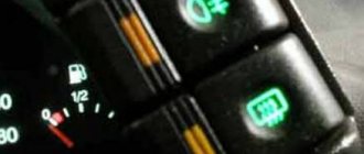
A heated rear window is a useful and very convenient option that helps keep your rear window fog-free and icy while still providing excellent visibility all year round.
Heating the rear window allows you to save money not only in winter, but also in autumn, when humidity rises and all the windows in the cabin begin to fog up. In a few minutes, the heated rear window melts ice and light snow, and also dries condensation that accumulates on the windows in case of rain.
All this is normal, but what if nothing happens when you press the button, in other words, what if the rear window defogger does not work? This is exactly what we will try to figure out today. You will learn how heating works, why it does not work and how to find a fault and repair the heated rear window of a VAZ.
How does the heated rear window work?
The heating principle is as follows. A voltage is applied to a conductive wire, called a heating element, causing the wire to heat up, thereby melting the snow and drying out the moisture. The heating system consists of a network of conductive wires, several fuses and a button. When the driver turns on the heated rear window, a warning light on the panel lights up and one of the relay contacts closes. The second contact is connected to the body, this is “minus”. Thus, current circulates in the heating system.
Rear window heating diagram for VAZ cars
Car electrical equipment
1 — headlight block; 2 — gearmotors for headlight cleaners*; 3 — fog lights*; 4 — ambient temperature sensor; 5 — sound signals; 6 — engine compartment lamp switch; 7 — electric motor of the cooling system fan; 8 — VAZ 2114 generator; 9 — low oil level indicator sensor; 10 — washer fluid level sensor; 11 — front brake pad wear sensor; 12 — wire tips connected to the common windshield washer pump**; 13 — windshield washer pump; 14 — headlight washer pump*; 15 — wire ends for connecting to the rear window washer pump on VAZ 2113 and VAZ 2114 cars; 16 — low oil pressure indicator sensor; 17 — engine compartment lighting lamp; 18 — wire lug for connection to the wiring harness of the engine management system or to the wiring harness of the ignition system on carburetor vehicles; 19 — windshield wiper gearmotor; 20 — VAZ-2114 starter; 22 — coolant temperature indicator sensor; 23 — reversing light switch; 24 — low brake fluid level indicator sensor; 25 - battery; 26 — sensor for insufficient coolant level indicator; 27 — relay for turning on fog lights; 28 — mounting block; 29 — brake light switch; 30 — plug socket for a portable lamp; 31 — lamp for illuminating the headlight hydrocorrector scale; 32 — parking brake warning lamp switch; 33 — backlight lamp connection block; 34 — switch for instrument lighting lamps; 35 — steering column switch; 36 — alarm switch; 37 — front seat heating element relay; 38 — ignition switch VAZ 2114; 39 — rear fog light circuit fuse; 40 — fuse for the front seat heating elements circuit; 41 - door lock circuit fuse; 42 — front ashtray illumination lamp; 43 — ignition relay VAZ-2114; 44 — cigarette lighter; 45 — glove box lighting lamp; 46 — glove compartment lighting switch; 47 — heater fan electric motor; 48 — additional resistor of the heater electric motor; 49 — heater fan switch; 50 — heater switch backlight; 51 — lamp for illuminating the heater levers; 52 — gear motors for electric windows of the front doors; 53 — right front door power window switch (located in the right door); 54 — gearmotors for locking front door locks; 55 — wires for connecting to the right front speaker; 56 — gearmotors for locking rear doors; 57 — wires for connecting to the right rear speaker; 58 — door lock control unit; 59 — wires for connecting to radio equipment; 60 — headlight cleaner switch; 61 — rear window heating element switch; 62 — relay for turning on rear fog lights; 63 — block for connection to the heating element of the right front seat; 64 — switch for rear fog lights: 65 — switch for the heating element of the right front seat; 66 — fog lamp switch; 67 — switch for external lighting lamps; 68 — left front seat heating element switch; 69 — block for connection to the heating element of the left front seat; 70 — wires for connecting to the left front speaker; 71 — left front door power window switch; 72 — right front door power window switch; 73 — wires for connecting to the left rear speaker; 74 — side direction indicators: 75 — lamp switch on the front door pillars; 76 — lamp switch on the rear door pillars; 77 — lampshade; 78 — canopy for individual interior lighting; 79 — block for connecting to the wiring harness of the VAZ 2114 electric fuel pump; 80 — trunk light switch; 81 — instrument cluster: 82 — trunk lighting lamp; 83 — display unit of the on-board control system; 84 — trip computer (not in all models); 85 — block for connecting the wiring harness of the engine control system; 86 — rear external lights of the VAZ-2114; 87 — rear internal lights; 88 — block for connection to the rear window heating element; 89 — license plate lights; 90 - additional brake signal located in the spoiler.
Causes of rear window heating malfunction
- Switches. If the heat is not working fully, the fuse is likely blown and should be replaced.
- Break up. It also often happens that current-carrying wires burn out or break, as a result of which the current does not go beyond the break. A wire break can occur due to abrasion or breakage, for example, due to incorrect repair.
- Faulty button or relay. If the rear window defroster button or relay is faulty, no current will flow.
- Contacts. Oxidation, breakage or wear of contacts leads to an unstable current supply and, as a consequence, to poor heating of the wires.
Most common reasons
It is worth noting that the heated rear window most often does not work in a VAZ-2115 car for the following reasons:
- fuse is blown;
- there is no contact at its terminal;
- The toggle switch that turns on the heating is broken;
- the relay has become unusable;
- contacts on the terminals of the heater circuit have oxidized;
- The threads have broken.
Fuses blow out quite often. This usually happens unnoticed by the car owner.
As a result, one or another device stops working. For this reason, you should pay attention to them first of all if you do not want to join:
- cigarette lighter;
- stove;
- burnout installed on the rear window, etc.
Replacing them with serviceable ones will solve the problem completely. In other cases, it will also be necessary to clean the terminals from dirt, and at least visually make sure that the power wires have not come off the buttons. If the relay is faulty, then it will need to be replaced - it is not very expensive and is quite easy to install.
Finding a broken rear window heating
The search is to identify an interruption in the circuit. We check the relays and fuses (mounting block F8 (20A) and F8 (20A), as well as the button, if everything is in order, you should look for breaks in the filament. To do this, first carry out a visual inspection. Turn on the heating and observe where the strands heat up and where No.
If a visual search does not produce results, you can use a voltmeter or multimeter. To search for a break using a voltmeter, turn on the ignition and heating, then connect one probe of the device to the ground of the machine, and wrap the other in foil and move it to the center of the conductive wire. In this case, the device should show a result in the range of 5 V. At the point where the device shows 0 V or, conversely, increases by more than 10 V, it can be assumed that there is a break at this point.
If the rear window heater fails, a voltmeter will help you find the break. The device is connected to the positive terminal of the heater, and the second probe moves smoothly along the filament only from the side of the negative terminal. At the point where the voltage drops to 0V there will most likely be an open circuit. This is where you will need glass repairs.
Complete electrical diagram of the VAZ 2114 with decoding
The complete package of electrical equipment of the VAZ 2114 can be divided into two types. The fundamental differences are due to changes in equipment depending on the year of manufacture and equipment of the car. In this case, the entire drawing can be divided into several zones.
- The engine compartment is responsible for providing voltage to sensors and instruments located directly inside the engine compartment.
- Salon compartment. The part is primarily used to connect the front and rear compartments.
- Instrument panel assembly. The pinout is displayed directly on the controls and dashboard. All elements of the on-board network are combined here and connected to buttons or indicators.
- Stern joint. The small module combines chain elements located at the rear of the machine. Typically, the segment is subject to frequent damage, which is due to the constant transportation of goods in the luggage compartment. When moving over obstacles, loads can damage sensitive equipment.
You can also separate small units – these are door units, windshield wipers and others. For ease of perception, each beam is considered separately.
VAZ 2114 instrument panel pinout
The terminals of all vehicle equipment are concentrated here. Due to the fact that the unit is located under the dashboard and is subject to constant condensation or fogging, some users treat it with hot melt adhesive. Even a thin coating can reliably protect the device from water ingress.
Elements are connected to devices or controls:
- 1 – switch key for heated rear glass;
- 2/6 – fog light switches, for rear/front module;
- 3 – plastic block for activating head optics and turn signals;
- 4 – fuse block;
- 5 – wiper mode switch;
- 7 – on-board system indication;
- 8 – supply voltage to the additional harness;
- 9 – dashboard;
- 10 – “male” for powering the on-board computer;
- 11 – terminal to the ignition device;
- 12 – for door wiring;
- 13/14 – fuses;
- 16 – ignition break;
- 17 – stove motor;
- 18 – secondary resistance of the stove;
- 19 – current supply to the ignition unloading relay;
- 20 – protective relay for rear fog lights;
- 21 – starter fuse relay;
- 22 – remote socket for a portable lamp;
- 23 – power supply for the cigarette lighter;
- 24 – for illumination of the glove compartment;
- 25-27 – illuminators;
- 28 – stove switch;
- 29 – tidy lighting with rheostat;
- 30 – stop switch;
- 31/32 – horn/hazard warning switch, respectively;
- 33 – backlight of the stove panel;
- 34 – fuse;
- 35 – protective relay for seat heating elements;
- Ш1/4 – mounting block jumpers;
- X1/2 – dashboard controls;
- A – protective ground output (usually black).
Repairing the heated rear window - how and with what?
- There are many options for repairing wires, one of which is a rear window heated wire repair kit. This category is represented on the market: Permatex and Quick. Such repair kits allow you to effectively repair large areas of damage, up to ten centimeters. The kit consists of stencils, a cylinder with polymer resin and the heating wires themselves. The repair is carried out as follows: we find the damaged area, prepare the required piece of wire, remove the protective film and glue the wire to the area using polymer resin. When everything is dry, the procedure can be repeated. After 1-2 days, turn on the heat and check the result.
- The second method of attaching rear window heating threads is to use conductive paste, such as Kontaktol. A special paste or glue that can conduct current is applied in a thin, clean layer to the damaged area. For more precise application of the paste, the work area can be sealed with tape. The paste takes about a day to dry, but if you have an effective heat source such as a hair dryer or a special heater, the drying time can be significantly reduced.
- There are also alternative “makeshift” methods for repairing heated rear windows. That's why some people use paint that contains copper-brass shavings. The paint is matched to the color of the threads, and the shavings are removed by shaving the material. You can use glue instead of paint. Alternatively, you can try connecting the break points using a soldering iron. I would like to note that in this case there will be a result, but it will not look very aesthetically pleasing.
This is my conclusion. I hope now you know what a heated rear window is, how to find its fault and how to repair the heated glass in several ways. That's all, thank you for reading to the end. I would be grateful if you share this article on social networks, it will help us in the development of this project. In addition, more people will know about our existence. Also, do not forget to leave your comments and add your recommendations to this article. All the best and see you again at VAZ repairs.
On VAZ cars, as on most foreign cars, the rear window is equipped with a heating function. It is very useful and is designed to maintain visibility through glass in bad weather.
Heating helps equally well both during rain and fog, when condensation forms on the glass, and in winter, when it is covered with a layer of frost.
But it also happens that the rear window heating 2114 does not work. There may be several reasons for this - we will look at them below, but first you need to understand - on what principle does the heating system itself work?
General concepts
In order for the glass to heat evenly and at a strictly defined temperature (sufficient to evaporate moisture, but not beyond safe limits), a special electrically conductive wire (thin flat wire) is used, which has a certain strictly standardized strength.
When current flows through it, it heats up, just like electric stoves and kettles, only at a much lower temperature. Thanks to this heating, in addition to the fact that it occurs evenly over the entire plane of the glass (after all, the wire is applied to it at equal distances), the latter dries quite quickly and is cleared of moisture.
Sometimes in winter it may seem to a car enthusiast that the heating is not working, because the glass does not defrost for a long time. In such a situation, there is a high probability that the heating is working properly, but its temperature is not enough to melt a significant layer of ice. You must manually remove the ice with a special scraper and then turn on the heat again.
Possible faults
There may be several reasons why the heated rear window of the VAZ 2114 failed.
The most common:
- blown fuse;
- the contacts in the fuse socket in the common block are coated with oxide;
- the switch is broken;
- the relay has failed;
- the heating element terminals are oxidized;
- internal network wiring burned out;
- The heating filaments themselves have broken.
The first two (and most common) reasons are quite simple to solve: you need to check the fuse and, if necessary, replace it with a new one (in the general block it is designated as F5). You should also check the contacts in the fuse box and clean them with sandpaper or a cloth soaked in kerosene.
If the fuse turned out to be good or was replaced, but the problem did not disappear, then the heated rear window button of the VAZ 2114 may have failed. You can check this, as well as the control relay, using a conventional tester (multimeter). To do this, in the first case, the output contacts “ring” in the on and off positions, and in the second, the supply voltage (its presence) on legs 1 and 9, as well as on relays 2 and 4 (the second one in the diagram) is monitored).
If all of the above elements have been checked and are working properly, you need to check with a multimeter all the wires included in the electrical circuit of the heating element. If a break is detected, the wire should simply be replaced with a new one.
The dashboard diagram (Fig. 1.1) includes controls:
1 – lever-switch for headlight or turn signal modes.
2 – nozzle for blowing the front door glass.
3 – instrument cluster.
4 – steering wheel.
5 – button to turn off sound signals.
6 – button to turn off the alarm. Pressing the button causes the warning light and direction indicators to flash.
Photo 1. Hazard switch off button
7 – ignition switch combined with an anti-theft device. Never turn off the ignition or remove the key from the lock while driving, otherwise the steering will be blocked and the vehicle will lose control. The ignition key can have three positions:
- 0 – “disabled”. Consumers are disconnected, the key can be easily removed. When the key is removed, the closing mechanism of the anti-theft system is activated. To guarantee the steering shaft block, turn the steering wheel left or right until it clicks. To turn off the anti-theft device, you need to insert the key into the ignition and, turning the steering wheel left and right, turn the key to position “I”;
- I – “ignition”. The ignition is on, the key is not removed, the steering is unlocked;
- II – “starter”. The key cannot be removed, the steering is unlocked. The position is achieved by turning the key to overcome the elastic force of the spring. The key is not locked in this position; it must be held by hand for the starter to operate. The ignition switch is also equipped with a starter activation unit while the engine is running.
To repeat turning on the starter after a failed start attempt, you need to move the ignition key from position “I” to position “0”, and then again to position “II”.
8 – switch lever for windshield washer and windshield wipers.
9 – immobilizer sensor, transmits a special code from the code key through the immobilizer to the engine control unit.
10 – set of signal lights for the on-board control system. The complex contains (Fig. 1.2): 1 – oil level drop signal; 2 – low level signal in the windshield washer tank; 3 – low coolant level signal; 4 – door open signal; 5 – signal of malfunction of the brake light and side lights; 6 – signal of wear of the linings on the brake pads; 7 – the signal indicates that the seat belts are not fastened.
11 – external lighting switch.
12 – block of keys for turning off fog lights, fog lights, heated rear window.
13 – trip computer, installed on some vehicles, designed to display one of the parameters: current fuel consumption (or average total fuel consumption), average speed, distance traveled, current time, time on the road.
15 – control lamp for anti-lock braking system (ABS). Installed in place of the plug, if equipped with an anti-lock braking system.
16 – airbag control lamp. If the pillow itself is present, it is installed in place of the plug.
17 – central nozzles of the ventilation and heating systems of the cabin.
18 – cover of the glove box (upper). To use the upper glove compartment while the lower glove compartment lid is open, press the upper lid lock lever. The lock lever is located in the niche of the lower glove compartment on top.
19 – side nozzle of the ventilation and heating systems of the cabin.
20 – glove box cover (lower). To open it, you need to press the lock handle to the handle. If the external lighting is turned on, a special illumination of the inside of the box will automatically work.
21 – magazine shelf.
22 – control panel for interior ventilation and heating systems.
23 – socket for audio equipment. It is planned to install audio equipment that meets international standards in size and mounting principle.
Watch a video of testing the dashboard of a VAZ-2115 passenger car here:
Possible repair options
All the breakdowns described above, due to which the rear window heating of the VAZ 2114 does not work, are quite common and can be eliminated without much additional cost or effort. A much more serious problem is damage to the heater itself, namely the breakage of its heating wires.
If this happens, you can solve the problem in several ways:
- independently repairs broken threads;
- install a small removable heater connected to the cigarette lighter;
- install a full double-glazed window with a fan.
If the conductive threads break, the best option is to restore them. Installing additional heating elements in a car can significantly increase the load on its on-board network.
To find the exact break point, you should carefully examine all the strands under a magnifying glass.
If you detect a power outage, you can try to reset the heating in one of the following ways:
- Connect the cleaned areas with a paste of conductive material.
- Connect with thin metal filings. To do this, sawdust is applied to the tear, and a powerful magnet is placed on the other side of the glass, which will temporarily hold it. While the sawdust is attracted to the magnet, you should quickly apply a coat of paint or BF glue to it.
- Solder the break point using POS-18 or similar solder (low tin content).
- Fix the gap with a special glue for restoring heating wires (it should be noted that this is quite rare and is not found in all car dealerships).
By completing the repair in this simple way, you can completely restore the operation of the glass heating system, even if there are numerous breakdowns.
Fuses and relays VAZ 2114 2115 2113
VAZ 2113, 2114, 2115 cars considered
Attention! The location of fuses and relays in the blocks may differ depending on the year of manufacture and vehicle equipment. You can see earlier modifications of fuse blocks on this page.
Fuses for the VAZ 2114 injector and VAZ 2115 injector are also described on this page.
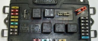
Where are the fuses and relays located?
The main part of the fuses and relays is located in the mounting block of the engine compartment.
To get to the block you need to press two latches and remove the cover
Using pliers installed in the block, remove the fuses
Useful video
For more information, watch the video below:
- The VAZ 2114 stove does not heat well, does not heat, does not work. Causes of malfunctions.
- Do-it-yourself adjustment and tuning of VAZ 2114 headlights
- Replacement and repair of VAZ 2110 starter
The rear window heating on the glass does not work, a splinter is torn off on one side, and on the other there is a piece of glass, not a handle, what to do, how to connect which cable is needed and where, where to connect the plus and where less
I checked all the fuses, the ignition button, the heating wire itself, checked everything with a test, started the engine, I think it's relay 9043747, if it's a relay, how to replace a Lada 2114 car? Help if possible!
Good visibility is important for safe vehicle operation. In the autumn-winter period, due to air temperature changes, the windows fog up and visibility through them deteriorates. The issue of glass transparency is especially relevant at night, when visibility already leaves much to be desired.
An effective way to combat fogging of car windows is to insulate them. The windshield is usually heated by direct streams of hot air. Typically, the rear window and rear view mirrors are heated electrically. On the interior side, conductive tracks made of high-strength metal in the form of thin strips are applied to the glass surface. When electric current flows through them, thermal energy is released. The glass heats up and the water evaporates. After a few minutes the glass becomes transparent.
Modifying buttons VAZ 2114 — DRIVE2
I bought a VAZ 2114 button (for subsequent installation in a UAZ) because of the indicator lamps on the buttons. Having connected it, I saw that there was a control on the dimensions, but not on the near one. Without thinking twice I decided to do it. We need: - soldering iron - straight hands :-))) - button - SMD LED, resistance
!The advantages of this modification are that you don’t have to touch the factory wiring of the car! ((((((ONLY FOR BUTTONS WITH SMD LED!)))))
We open the button with a scalp, disassemble it further (IT’S BETTER TO DO THIS WHEN IT’S ON!) Unsolder it, take out the board, where to solder it, and SOLDER IT IN. Then we reassemble in the reverse order (BE CAREFUL AND DON’T LOSE THE SPRINGS) GOOD AND DONE! (((((A CORRECTLY ASSEMBLED BUTTON WORKS THE SAME! SEE THE PHOTO!
Electrical diagram for connecting the heater
In order to successfully diagnose and repair the rear window heating system of a car at a professional level, you need to know the heater connection diagram and understand the principle of its operation.
The photo shows a typical diagram of connecting the rear window of a car to the on-board wiring. Let's look at how this works.
The supply voltage from the positive terminal of the battery through the ignition switch and fuses is supplied to the heater switch and to power contact 30 (or 87) of the relay. The negative terminal of the battery is connected to the body, one of the terminals of the window defroster is also connected to the body. When you press the heater power button, voltage is applied to the relay coil, the relay is activated, the power contacts close and connect terminals 30 and 87 of the relay together. Current enters the heater, travels through a group of wires connected in parallel, and returns through the housing to the negative terminal of the battery.
Diagram of the VAZ engine management system with BOSCH controller - ECM 21104 1.6 16V
1 – block of the ignition coil wiring harness to the ignition system harness; 2 – block of the ignition system harness to the ignition coil wiring harness; 3 – ignition coils; 4 – immobilizer warning sensor; 5 – immobilizer control unit; 6 – spark plugs; 7 – nozzles; 8 – diagnostic block; 9 – block of the ignition system harness to the ABS cabin group harness; 10 – controller; 11 – electric fuel pump; 12 – block of the ignition system harness to the fuel level sensor harness; 13 – fuel level sensor harness connector to the ignition system harness; 14 – block of the ignition system harness to the injector harness; 15 – injector harness block to the ignition system harness; 16 – block of the ignition system harness to the side door harness; 17 – speed sensor; 18 – idle speed regulator; 19 – throttle position sensor; 20 – coolant temperature sensor; 21 – mass air flow sensor; 22 – oil pressure warning lamp sensor; 23 – phase sensor; 24 – oxygen sensor; 25 – crankshaft position sensor; 26 — knock sensor; 27 – solenoid valve for purge of the adsorber; 28 – oil level sensor; 29 – coolant temperature indicator sensor; 30 – block of the ignition system harness to the instrument panel harness; 31 – instrument panel harness connector to the ignition system harness; 32 – ignition relay; 33 – ignition relay fuse; 34 – fuse for the electric fuel pump power supply circuit; 35 – electric fuel pump relay; 36 – electric fan relay; 37 – controller power supply fuse; 38 – ignition system harness block to the air conditioner connector; 39 – instrument cluster; 40 – ignition switch; 41 – electric fan of the cooling system; 42 – on-board control system unit; 43 – starter relay; 44 – contacts of the 8-terminal blocks of the instrument panel harness and the front harness; 45 – contacts of the 21-terminal blocks of the instrument panel harness and the rear harness; 46 – trip computer; 47 – diagnostic connector.
Rear window defroster malfunctions
The rear window defroster functionality is ignored until the glass fogs up or freezes. After turning on the heating, it suddenly turns out that after a few minutes the glass did not become transparent or visibility appeared only through part of the glass. Depending on the external manifestation, even without measuring instruments, you can immediately make an assumption about the cause of the breakdown.
Please note that the heated rear window and rear view mirrors can only be turned on when the ignition key is in the ON position. In some car models, the heater can only be turned on when the engine is running. This is done to avoid severe battery discharge, since the rear window defroster consumes current from 10 A to 25 A, depending on the car model. For comparison, a car headlight consumes only 5 A.
The heater does not turn on
If the indicator on the heated rear window button does not light up after pressing it, then most likely the fuse has blown or the key itself is faulty. If the indicator is on, but not a single wire heats up, the cause of the malfunction may be the relay or connectors for connecting the heating element to the wiring. In this case, using the documentation for a specific car model, it is necessary to determine the location of these parts and replace the faulty one. It is not always possible to quickly find the installation location of the relay, but there is a way to indirectly check its performance, which will be discussed below.
The glass is slowly fogging up
Sometimes it happens that after turning on the heating, the glass sweats for a period of time significantly exceeding several minutes. In this case, if it is not very cold outside, the reason may be poor contact of one of the connectors of the electrical circuit. As a result, the contact resistance increases, the current is limited and, as a result, the power allocated to the glass heater filaments decreases. To check for the presence of such a malfunction, it is necessary to measure the voltage at the input terminals of the heating element and battery with a DC voltmeter (multimeter or dial tester turned on in DC voltage measurement mode). The voltages should not differ by more than one volt.
Horizontal streaks of fog remain on the glass
And finally, the most common case of malfunction of the rear window heating system of a car is a break in one or more heater wires attached directly to the glass. This type of malfunction is immediately visible by the horizontal stripe of residual fogging on the glass after turning on the heating element.
The conductive tracks on the rear window have low mechanical strength and are easily destroyed upon contact with them. Therefore, it is prohibited to remove frost and ice from the glass with a scraper. Clean only with a soft cloth. It is also necessary to ensure that when transporting large objects they do not rest against the rear window. As a rule, individual heater filaments stop working due to their accidental mechanical destruction. After turning on the heating, streaks of fog or frost remain in the area of the damaged wire.
While renovating my apartment, I was carrying floor skirting boards in the car and didn’t notice how one of them leaned against the rear window. Some time later, when it was necessary to insulate the rear window, I saw the result of my carelessness. The two heater strips running through the center of the glass did not overheat, which greatly reduced visibility of the road. Upon visual inspection, a gap of approximately 1 mm wide was found on the non-functioning strips, as in the photograph. The question arose about the need to repair the heated rear window.
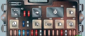
Wiring diagram VAZ 2114 injector - mounting block
Wiring diagram of the mounting block VAZ 2114 injector 8 valves with a full description
K1 - relay for turning on headlight cleaners; K2 - relay-interrupter for direction indicators and hazard warning lights; K3 - windshield wiper relay; K4 - lamp health monitoring relay; K5 - power window relay; K6 - relay for turning on sound signals; K7 — relay for turning on the electric heating of the rear window; K8 - headlight high beam relay; K9 - relay for low beam headlights; F1-F20 - fuses; X11 - terminals of the wiring harness block. The power supply circuit of the injection systems is protected by a fuse-link made of wire with a cross-section of 1 mm. Powerful consumers (starter, headlights) are connected to the VAZ 2114 injector wiring diagram via a relay.
F1 (10A) - Headlight cleaners. Relay for turning on headlight cleaners (contacts). Valve for turning on headlight washers.
F2 (10A) - Direction indicators and hazard warning relay-breaker. Hazard warning lamp.
F3 (10A) - Rear lights (brake lamps). Interior lighting.
F4 (20A) - Rear window heating element. Relay for turning on the heated rear window. Socket for portable lamp.е
F5 (20A) - Electric motor of the engine cooling system fan and switching relay (contacts). Sound signal and relay for its activation.
F6 (30A) - Power windows for front doors. Relay for turning on electric lifts.
F7 (30A) - Headlight cleaners (in operating mode). Relay for turning on headlight cleaners (winding). Heater fan motor. Window washer motor. Rear window wiper motor. Rear window washer timing relay.
F8 (7.5A) - Left fog lamp.
F9 (7.5A) - Right fog lamp.
F10 (7.5A) - Left headlight (side light). Left rear light (side light). License plate lights. Engine compartment lamp. Instrument lighting lamps. Indicator lamp for external lighting. Heater lever illumination display.
F11 (7.5A) - Right headlight (side light). Right rear light.
F12 (7.5A) - Right headlight (low beam).
F13 (7.5A) - Left headlight (low beam).
F14 (7.5A) - Left headlight (high beam). Indicator lamp for turning on the high beam headlights.
F15 (7.5A) - Right headlight (high beam).
F16 (15A) - Direction indicators and relay-breaker for direction indicators and hazard warning lights (in turn indication mode). Turn signal indicator lamp. Rear lights (reversing lamp). Gearmotor and windshield wiper activation relay. Generator excitation winding (when starting the engine). Oil pressure warning lamp. Air damper control. Coolant temperature gauge.
The VAZ dashboard has an electronic combination, as well as conveniently located backlighting. The lamps are illuminated from the inside, which is a feature of the 14th Lada.
Thanks to the instrument panel, the driver knows all the information he needs, what is the reserve and consumption of gasoline, mileage, etc. The panel should be easy to operate with a clear overview of the icons, scale, gauge and indicators.
What is the state of the automobile systems responsible for road safety, driving speed, the rest of the way to the intended object, rational engine operation and gasoline consumption, the operation of the suspension and electrical equipment - all this should be reflected on the control panel.
Signal lamps and equipment control devices must be required on the panel. There are a total of 19 symbols on the panel.
How to find the location of a broken glass heating filament
It is not difficult to determine which heater wire is in the reef, since fogging in the area where it passes does not disappear when the heater is operating. Therefore, in order to easily find a faulty thread during repairs, it is advisable to count the number of threads from top to bottom and remember which of them is in the break, so that then, during a visual inspection, try to find the place of its damage. But the thread break is so small that it is impossible to detect it visually. So a DC voltmeter, ohmmeter or voltage indicator will help in your search. To quickly find the location of a fault in the heating element, you need to imagine how it works and works.
The design of the heating element of the glass heating system
A natural question arises: why does it happen that only one or several threads in the heater do not work, while the rest work? To answer this question, you need to familiarize yourself with the design of the heating element.
The heating element of the rear window of a car is designed as follows. Two conductive bars 1 and 2 are attached to the sides of the rear window. Cores made of high-strength material are attached to these bars. Each wire has a resistance of approximately 10 ohms. The number of threads depends on the height of the glass. Thus, each wire is a separate heating element, the operation of which does not depend on the others. A parallel circuit for connecting heating elements is used. This circuitry ensures high reliability of the heating element, since the break of one or more wires does not lead to a complete stop in its operation.
Finding a broken heater filament using a voltmeter
To work, you will need any DC voltmeter with a measurement limit of 15 V. Any tester with a dial scale or a digital multimeter will be suitable as a voltmeter. Before starting work, you need to turn on the heating element.
Since one of the heating element buses is connected to the car body, the negative terminal of the voltmeter can be connected to the car body; Any screw or bolt screwed directly into the housing will do. The alligator clip is more convenient to attach to the trunk lid lock bracket.”
Since it is difficult to see visually with transparent glass whether the heating element is heating up, touching the positive probe of the voltmeters on bus 1, and then on bus 2, you will immediately understand. Bus 1 should be +12 V, and bus 2 should be 0 V. It's possible that your car's left bus is grounded and the right bus is energized. If the busbars are not accessible, measurements can be taken by touching any of the wires with a probe at the points of connection with the busbars, that is, where they exit the rubber seal. In the photo these are points 1 and 5.
Using a voltmeter it is easy to determine which part of the heating system is faulty. If the heating element is turned on, the power indicator on the button is on, and there is 12 V on bus 1, but there is no heating, then the wiring on bus 1 is OK. If there is no voltage on bus 1, it means there is a bad contact in the power supply terminal on bus 1, or the relay is faulty. If 12 V is present not only on bus 1, but also on bus 2, you need to look for a bad contact in the terminal for connecting the cable to bus 2 or in the circuit connecting the cable to the vehicle ground.
Finding the location of the thread break
After checking the heater power system, you can begin to determine the location of the heating wire break. The wire represents a tape resistance of about 10 ohms, so the voltage at different points has different values. Therefore, at point 1 the voltage will be 12 V, at point 3 - 6 V, and at point 5 - 0 V. Therefore, even without knowing which of the wires is in the break, it can be easily determined by measuring the voltage in the middle of the length of all threads . On broken wires the voltage will be 12 or 0 V. If the voltage is 12 V, the break point is on the left, and if 0 V, then on the right.
Now just slowly bring the probe to the break, instead of a sudden change in voltage, there will be a break. For example, in the photo this is a piece of thread between 6 and 7 points.
Finding a broken thread using an ohmmeter
Using a multimeter or pointer tester in resistance measurement mode “title =” How to measure “> you can also successfully find the location of the wire break. Grounding won't work.
If the wire break is unknown, you need to connect one end of the ohmmeter probe to the ground terminal, and touch the center of the heater wires with the other one in turn. The wire on which the ohmmeter shows resistance is twice as large and will be broken. For reference: the resistance of all wires in relation to bus 1 or bus 2 should be 2-3 ohms. If the filament breaks, the ohmmeter will show 4-6 ohms.
If a damaged wire is detected, it is necessary to move the probe tip from the center to any direction. If the resistance increases as the probe moves towards busbar 1, then the break occurs in the gap between busbar 1 and the contact point of the probe. For example, at the point indicated by points 1 and 2. As soon as the probe passes the gap, the resistance will sharply drop several times. If the resistance decreases, this means that a wire break occurs between the probe and bus 2. For example, at the point indicated by points 3 and 4. Then you need to move the probe towards bus 2, and when the resistance drops sharply, at that moment there will be a pause.
Locate broken threads with an automotive tester probe
If you do not have a voltmeter or ohmmeter, you can find the break point of the heating element filament using a homemade automotive tester probe, consisting of a single LED and a current-limiting resistor. I made the tester for myself a long time ago, although I have measuring instruments. The homemade car tester is always in the glove compartment of my car, and I have had to use it more than once.
Detecting a broken wire using a tester probe is no different from searching with a voltmeter. The indicator in this case will not be an arrow or number, but an LED glow.
Before you start searching for a damaged filament using a probe, supply voltage must be applied to the heating element. First, the presence of voltage on bus 1 is checked, the LED should be lit, if the LED is not lit, then the error lies in the power supply circuit of the power supply. Next, the voltage on bus 2 is checked; the LED should not light up; if it lights up, it means the contact at the point where the wire is connected to the bus or housing is faulty.
To find where the heater filament breaks, you need to slowly, lightly touching the filament, move it along the end of the probe. At the point where the LED goes out or lights up and the wire breaks. For example, in step 6 the tester LED will light up, but in step 7 it will not. In my case, the wire breaks were large, and the tester was only useful for checking the quality of the repair.
How to find a breakdown
To find out exactly what the reasons for the failure are, you only need a standard voltmeter, which every self-respecting car enthusiast should have.
By simple manipulations with this measuring device, the problem will be identified very quickly. You should start checking the heating element filaments with the following steps:
- the metal tips of the probes are wrapped in tin foil (this will avoid damage to the tracks);
- turn on the ignition;
- check whether the heating button is pressed;
- one probe is applied to the plus of the heating element mounted on the rear window;
- the second is installed approximately in the center of the thread.
If the device shows 6 volts, this means that there is no damage in this area. If the tester produces 12 volts, the gap is located somewhere in the segment between the probes.
If there are 10 volts, we can confidently say that the gap is located between the minus and the center of the track. In this situation, connecting one probe to the negative output will allow you to more accurately determine where the damage is located. At the same time, the second one must be carefully guided along the thread from the plus to the opposite end. Finding the exact location of the break is indicated by an increase in voltage from zero to 5 volts.
If you don’t have a voltmeter at hand, then the break will also be easy to find visually. To do this, you will need to wait until the windows in the car fog up, and only then turn on the heating. Where the track remains operational, the moisture will begin to evaporate noticeably. Condensation will remain in de-energized areas. It is these sections of the heating element that will need to be examined in detail. To do this you will need a magnifying glass.
If the heating is completely out of order, it can be replaced with a removable model, which is attached to the glass using special suction cups. It is connected to the car's electrical network, like many other devices, through the cigarette lighter.
There are also modifications on sale in which an additional fan is installed. But this option is not very practical because it requires too much electricity.
Methods for repairing heating element filaments
There are several ways to restore the functionality of a heating wire at home.
Using conductive pastes and adhesives
The simplest and most effective is with the help of special repair kits, for example DONE DEAL DD6590, designed for repairing threads and contacts of the rear window heating for both amateurs and professionals. The good thing about this method is that it does not require tools or materials. It is enough to apply a little conductive paste according to the attached instructions to the place where the syringe thread is broken, wait for the paste to harden and complete the repair. But this set costs more than $15.
The second method is similar to the previous one. But instead of a proprietary set, purchased conductive adhesives are used, for example. Glue is applied to the place where the thread breaks, covering the entire part of the thread by one centimeter on each side. To obtain a neat look, use a stencil made of electrical tape or adhesive tape. For reliability, glue is applied twice. It is recommended to lay a piece of tinned copper wire with a diameter of 0.3-0.5 mm between the layers of conductive glue.
It is believed that conductive paste or glue for repairing glass heater wires can be made independently by mixing paint or glue with brass filings in a one-to-one ratio. The resulting composition is applied through a stencil in a thin layer until the thread breaks in several layers. But the reliability of this technology has not been confirmed by practice.
Electroplated copper deposition
Another method is copper electroplating. The method for repairing the heater filament looks interesting. But from personal experience I can say that the reliability of such coatings at home is low. Therefore, I hesitated to use this technology.
Using soft soldering
The mechanical method of restoring the integrity of the rear window heater filaments using soft soldering has become widespread. I tested the reliability of this method when repairing the rear window heating threads in my car. The step-by-step instructions below, based on my experience, will allow you to easily repair your heater wire yourself in minutes with virtually no cost.
On the advice of Internet theorists, I made a big mistake and tried to clean the thread with sandpaper. As a result, instead of breaking a thread 1 mm wide, a break of more than 1 cm occurred. The thread ribbon is very thin, only a couple of tens of microns, and can be erased even with the finest grit sandpaper instantly. However, the heater wires are not covered with anything, and it is enough to degrease the welding area with a rag moistened with alcohol or acetone.
If the width of the wire break is less than 1 mm, you can do without soldering an additional conductor. In my case, the gap width was large, and I had to prepare a piece of copper wire for the jumper in advance. A current of about 1 A flows through the heater conductor, based on this we select a wire with a cross-section of 0.17 mm 2, which corresponds to a diameter of 0.45 mm, according to the table of wire sections. The length of the copper jumper should be equal to the width of the wire break plus 2 cm. Before soldering, the jumper must be tinned with a thick layer of POS-61 tin-lead solder. There is no need to tin the heater wire.
To ensure that the solder adheres securely to the heater wire, before soldering the jumper, coat the wire in the soldering area with a brush with a thin layer of zinc chloride flux.
After this, the jumper is pressed against the heating wire and heated for a second with a 12 W soldering iron. The hand is moved to the side. The jumper should be kept on a string. Trying to pull it out to check the quality of the solder is unacceptable; it will fall off and tear off a piece of the heater wire. Unfortunately, this has not been tested empirically. As a result of the experiments, we had to solder a jumper 5 cm long.
After soldering one end of the jumper, the other is pressed tightly against the wire and is also heated with a soldering iron. At the end of welding, the glass is thoroughly washed with water to remove residual acid flux.
Finally, for reliability, even if this is not necessary, I covered the jumper welded on top with transparent superglue “Moment” based on cyanoacrylates, the heat resistance of which is about 70 ° C. The heater does not heat up to the above temperature.
As a result, the time to repair a broken thread with your own hands, taking into account all the preparatory work, was no more than ten minutes. The repaired threads have been in use for more than three years.