Print this article Font size 16
In our material today we will talk about how the ignition module on a VAZ 2114 is checked, how it works and why so much in the car depends on its functional state.
Ignition module
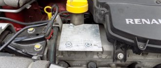
VAZ 2114 ignition module and its purpose
The VAZ 2114 8 valve ignition module is a special device, the purpose of which is to convert electrical energy coming from the generator into a current with a very high voltage. In addition, the module also plays the function of a distribution device that diverts increased voltage to the spark plugs.
By its design, it is a paired system, including two pairs of windings, as well as a commutator. The purpose of the latter is to alternately switch the incoming low-voltage electricity from one coil to another.
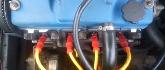
The ignition module, unlike ignition coils (which were used in earlier periods of the automotive industry), has not two, but four pairs of terminals, which are used to connect high-voltage wires, which, in turn, go to the spark plugs.
Pulses in the module, in this case, appear alternately in pairs - first on connectors 1 and 4, and then on 2 and 3. The ignition module itself is controlled using a special electronic unit.
Ignition module block
Coolant temperature sensor (DTOZH)
The coolant temperature sensor is installed in the thermostat housing and is used to turn the engine cooling fan on and off. It should be noted that turning on the fan is not the only task of this sensor. DTOZH adjusts the fuel mixture to maintain higher engine speeds when warming up, that is, if the coolant in the car is below operating temperature, the sensor will give readings about the enrichment of the fuel mixture to warm up the engine faster.
Signs of DTOZh malfunction:
- The cooling fan does not work;
- No warm-up speeds;
- The car does not start well;
- Increased fuel consumption;
Possible reasons for failure of the ignition module
Generally speaking, the ignition module is a completely reliable device, and its breakdowns are quite rare. At the same time, the weakest point inside the module is the primary windings of each of its coils - it is on these windings that high voltage is generated, so sometimes breakdowns, breaks or melting of the turns can occur there.
The main reasons causing overloads and improper operation of coils, leading to their breakdowns, are:
- use of unsuitable, faulty or dirty spark plugs;
- frequent spark checks;
- operation of the module with disconnected or damaged high voltage wires;
- high vibration of the fixed module, causing damage to the factory soldering inside it;
- poor contact inside the low-voltage wire connectors.
Ignition module failure
In addition, a fairly common cause is the usual ingress of water into the module (which often happens when the car is operated in a damp environment or after washing).
Loss of dynamics
The VAZ 2114 model has never been distinguished by high dynamics, so even the slightest decrease in engine efficiency affects the use of the car. Loss of dynamics is a clear sign of improper operation of the ignition system or fuel supply system. When considering the signs of problems with the motor, one cannot fail to mention the loss of engine power as one of the key symptoms of its breakdown. If the module malfunctions, leaks in the paired cylinders are clearly observed, which manifests itself in low engine efficiency. It is clear that cylinder failure, even for a short period of time, does not allow the engine to operate at its full capacity. Operating a vehicle with reduced power is fraught with increased fuel consumption and uneven wear of the piston group.
Important ! If there is a sudden loss of power, you should stop driving the vehicle and begin repairs immediately.
The MZ cannot be quickly repaired, so if it malfunctions, a new unit should be installed on the machine. For reliability, you should “throw” a known working element of the ignition system into the car, and then check for changes in the operation of the unit.
Signs of coil malfunction
Before starting an instrument test, you can try to determine whether the ignition coil of the VAZ 2114 8-valve injector is working by indirect signs (in some cases they are enough to verify a breakdown).
These include:
- instability (intermittency) of idle speed;
- the engine gains speed with great difficulty;
- “triple” when the engine is running;
- The speed gain while driving occurs in strong jerks.
Connecting the ignition unit
If these signs are present (especially if there are several of them), you can either immediately replace the faulty module, or finally establish the fact of its malfunction using instrumental analysis.
Difficult launch
Studying the signs of a malfunction of the ignition module on a VAZ 2114, one cannot help but note the difficulty of starting the engine with such a problem. Starting the engine cold or hot on a working car is the same. A damaged MH turns this procedure into a complex process. It is not the first time that the engine can be started. The reason for this is misfires due to a faulty module, which manifest themselves as “sneezing” of the engine.
If the motor is faulty, during the process of starting the car, the spark plugs begin to flood, which makes starting even more difficult. You should not delay repairing the car with such a malfunction, because... Even with a successful start, you should not drive the car with only two working cylinders. The problem with starting an engine with a faulty motor is especially obvious when it is “hot”.
How to check the malfunction of the VAZ 2114 ignition module on your own?
In order to start checking, you will need a measuring device - a tester. Before starting the measurement, the wire blocks are removed from the connectors. Each block has its own slot (A, B, C, D).
Checking the VAZ 2114 ignition module with a multimeter:
- turn on the car engine;
- set the multimeter switch to measure direct current up to tens of volts;
- one of the probes of the device is connected to connector D, the second to ground. If there is power, the screen will show 12 volts;
- switch the multimeter to ohmmeter mode up to tens of ohms;
- one probe is connected to connector C, the other to ground. If everything is in order, the device will show less than 1 Ohm;
- switch the multimeter to voltmeter mode up to tens of volts;
- one probe is connected to connector B, the other to ground. If a voltage of at least 0.3 Volts is displayed, then everything is fine (a clear pulse comes from the Hall sensor);
- The last measurement with connector A is carried out exactly as in the previous case.
Checking the ignition unit with a multimeter
Before you start testing the ignition module, you should carefully check the quality and reliability of the contact of all wires approaching and departing from it - perhaps this is the only reason.
Another testing method is to directly check the secondary coils for breakdown.
It is performed according to the following scheme:
- all wires are removed from the connectors;
- the multimeter is set to ohmmeter mode up to tens of kOhms;
- the probes are alternately installed in paired connectors (1 and 4, 2 and 3);
- if the windings are in good condition, both measurement results will be the same (on average, they should be equal to 5.4 kOhm). If the resistance turns out to be much higher, then there is an internal break in the turns; if it is much lower, there is a breakdown.
Checking high voltage wires
Also, there is another, easiest way to check the ignition coil of a VAZ 2114 - simply replace it with a new one, completely similar. If after replacement the car began to work properly, then the reason was definitely in the module.
conclusions
As a rule, the ignition module is not restored and is simply replaced with a new one. There is no guarantee that he won't start bucking again. This will save a lot of gray brain cells and save a lot of personal time, which can be spent on something more necessary. It's better to buy a new one and not worry.
However, as children, we all loved to take toys apart to find out what was inside and how everything worked. It’s not a pity to try to disassemble a broken unit, but still throw it away if nothing works. But if you repair it, you will get so much pleasure and pride in yourself!
Ignition module repair
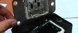
Due to the fact that the design of the module consists of a pair of coils, its maintainability is extremely low. So, if there is a breakdown, breakage, fusion of the turns, as well as other damage inside the coils, then nothing can be done here - all that remains is to replace the failed module with a new, similar one. The only case when you can try to solve the problem without purchasing a new device is if the solder is damaged.
This can be found out by testing (using the methods described above). If the serviceability of the secondary windings has been established, you can try to open the module cover and visually determine the damage to the soldering.
If such damage cannot be determined, then you can simply try to thoroughly solder all the contacts inside, then install the module in place and start the engine - if this was the cause of the breakdown, then the car will start working properly again.
Crankshaft position sensor (CPS)
DPKV is installed near the timing belt, namely near the crankshaft gear. This sensor is responsible for counting the crankshaft revolutions from the generator belt pulley. DPKV is involved in the formation of the spark necessary to ignite the fuel mixture in the combustion chamber. If the crankshaft position sensor fails, the car engine will not start.
Signs of DPKV malfunction:
- The car's internal combustion engine does not start;
- Spontaneous stop of the internal combustion engine;
- Uneven operation at idle and high speeds;
System replacement
If repairs fail to restore the device’s functionality, you will need to replace the module with a new one. At the same stage, you can move the module to another location, but we do not recommend doing this. When replacing, experts usually recommend using GM devices - these modules have proven themselves to be reliable devices. As for the price, it may vary depending on the country and region of residence, but on average it varies around 30-35 dollars or about two thousand rubles. More detailed and visual instructions for replacing the ignition coil along with high-voltage wires are shown in the video below (the author of the video is the STO TONN channel).
The replacement procedure can be done with your own hands; usually this task does not cause difficulties for motorists, and no specific tool is needed for this. All you need is a new block, a set of wrenches and rags. In general, the replacement procedure can be carried out in the garage or directly on the street.
If you do not know how to remove the ignition module and change it taking into account the pinout, then follow these steps:
- First you need to open the hood and turn off the power to the on-board network; to do this, disconnect the battery. It is not necessary to remove it, you can simply disconnect the negative terminal.
- Next, dismantle the high-voltage cables from the installation site, while marking their location separately on the sheet so as not to confuse them later, or put marks. Please note that you cannot change the seat wires, as this may lead to breakdown of the new module that will be installed in place of the old one.
- Then disconnect the wiring connector from the unit itself; for this you will need a 13mm wrench. Using the wrench, you need to unscrew the nuts securing the device to the engine.
- After unscrewing the nuts, the module can be dismantled. Using a rag, wipe down the installation area and the area around it. Check the new unit for damage, after which you can install it. The installation procedure is generally similar to the removal process, only done in reverse order. When installing, do not forget to connect the high-voltage cables correctly. If you have any difficulties at this stage, look at the module cover - the wire numbers should be marked on it.
Examination
Often problems with MH begin after replacing high-voltage power wires. Many people may simply make a mistake by mixing up the connection points to the candles. The pin numbering scheme is presented below.
Also, owners of the injection-type VAZ-2114 often replace the standard wires with modern silicone analogues. This is absolutely impossible to do. Silicone high-voltage wires have significantly higher resistance. When replacing, it is also important to consider the length of each wire. Standard wiring has the following parameters:
- The wire of cylinder 1 has a length of 56 cm and an operating resistance of 2.5 to 3.8 Ohms.
- A 44 cm long wire with an operating resistance of 2 to 3 Ohms goes to the second cylinder.
- 3 wire 36 cm long, resistance from 1.6 to 2.6 Ohms.
- 4 wire 32 cm long, resistance from 1.4 to 2.1 Ohm.
This is worth considering, since high resistance significantly reduces the spark discharge current.
Also, a problem with the ignition module may arise due to problems with the fuse responsible for its protection. The fuse is located behind the cover under the dash on the front passenger's side. This is the very first fuse located between relays 1 and 2. The element should be checked for the presence of a working jumper inside the housing. The test can be carried out visually, or using a tester in dial mode. Be sure to replace the burnt-out protective element with a complete analogue, rated 15 amperes. It is also worth checking the incoming voltage.
This requires:
- Set the tester to DC voltage measurement mode up to 20 volts.
- Connect the red test probe to the fuse terminal.
- Connect the black probe to ground.
- Turn on the ignition.
The voltmeter should give a reading equal to the battery charge. If there is voltage, it means it is reaching the ignition module.
Module
Many owners of the car described do not know how to check the VAZ-2114 ignition module using a multimeter. First you need to test the device with the engine running. This requires:
- Start the power unit.
- Ask an assistant to keep the speed within idle.
- Wear a glove or take a dry cloth.
- Remove the power wires from the module sockets one by one.
Each removed wire must be brought to the power unit block. Without touching, a spark should discharge from the tip. A blue spark and a discharge accompanied by a crackling sound will indicate the necessary supply of discharge current. In this case, the engine should respond to the removed working wire by reducing the speed. If a wire is detected from which the spark does not come or it is quite weak, the engine speed will not change.
The previously described error codes from the on-board computer can also help in finding the wire with no spark.
For more effective testing, it is necessary to dismantle the ignition distribution device and carry out a test with a tester. This is easy to do if you follow these instructions.
First you need to dismantle the device. This is done as follows:
- Disconnect the ground terminal from the battery.
- Remove 4 high-voltage wires from the MZ sockets.
- Disconnect the electrical power plug.
- Unscrew the 3 nuts securing the module.
- Remove the device.
Next, a mandatory visual inspection of the device is carried out. The ignition module is a rather fragile device. The presence of defects on the housing, cracks and dents, can cause an internal short circuit. You also need to pay attention to the sockets for power cables. There should be no oxidation or dirt on the terminals. Any malfunctions should be eliminated by cleaning with a solvent. Next you need to check the connecting plug. Its contacts also need to be cleaned. Below is a step-by-step guide on how to check the VAZ-2114 ignition module with a multimeter.
Checking the connecting plug
First you need to check the incoming voltage to the module. This is done as follows:
- The multimeter is switched to voltmeter mode to measure DC voltage.
- The red measuring probe is connected to the incoming half of the module plug, with the central contact. It is he who is responsible for powering the device.
- The black test probe is connected to ground.
- Turn on the ignition.
The tester should show a voltage of 11.5–14 volts, equal to the battery charge.
Next, the incoming signal is checked. The voltmeter remains in the same position.
- The red probe of the tester is connected to contact “1” of the coming side of the plug. This contact is responsible for the distribution of pulse current for the cycle of candles 1–4.
- The black probe connects to ground.
- It is necessary to crank the starter a few turns.
The voltmeter should show pulse voltage. Contact “3” on the plug is checked in the same way.
Module plug
For this test, you need to switch the multimeter to resistance measurement mode. Next you need:
- Connect the red control probe to terminal “1”.
- Connect the black control probe to terminal “3”.
- The operating resistance should be within 0.5 Ohm.
In this way, both secondary windings of the ignition coils are checked. Any deviations in resistance will indicate an internal violation of the integrity of the winding.
Using the following test, the presence or absence of a short circuit is checked.
- The multimeter remains in resistance measurement mode.
- Connect the red test probe to the central contact of the plug.
- Connect the black test probe to the device body.
- The tester should not show any results. This will indicate that there is no internal short circuit. Any minimal resistance during this test is reason to replace the module.
The following check is needed to test the primary windings. The check is carried out as follows:
- The multimeter is switched to resistance measurement mode.
- Insert the red measuring probe into the “1” socket for high-voltage wires.
- Insert the black measuring probe into socket “4”.
- The operating resistance of the primary phase windings is 0.5 Ohm. Any data that differs from the nominal value can be recognized as the presence of an interturn short circuit in the primary winding of cylinders 1–4.
The test of sockets “2” and “3” is carried out in a similar way. Their operating resistance should also be 0.5 Ohm.
Additionally, you can check in the same way, but between sockets “1” and “2”. There are no internal connections between them. If there is resistance, the part is considered unsuitable for further use.
Phase sensor (PF)
The phase sensor is located:
- In 16-valve engines near the intake camshaft gear;
- In 8-valve engines from the end of the cylinder head near the mass air flow sensor;
Serves for phased fuel injection. It is a fairly reliable sensor that rarely fails. The design of the sensors for 8 and 16 valve engines is different and is not interchangeable.
Signs of DF malfunction:
- Increased fuel consumption;
- Engine vibrations;
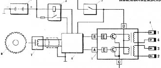
Connection diagram
Mechanism connection diagram
You can find the module itself using high-voltage cables - from the spark plugs they go straight to it. The diagram given in this article will allow you to easily replace the mechanism. The device connection procedure can be carried out using one of two methods. When the short circuit is dismantled and when it is located at the installation site in the engine compartment of the vehicle.
If the module is in front of you:
- Contacts numbered 1 and 4 go to one winding, as for contacts 2 and 3 - they are connected to another winding.
- After this, the leftmost high-voltage cable is connected to cylinder 1 (the bottom one in the diagram).
- Another high-voltage wire is connected to the second cylinder, only this time it’s the top one.
- The right high-voltage wire (top) goes to cylinder 3.
- Accordingly, the lower high-voltage cable must be connected to the last, fourth cylinder.
If the assembly is connected to a motor, then the pinout of high-voltage cables will be more complicated, since the mechanism itself is installed at an angle:
- The central lower wire is connected to the first cylinder.
- To the second - left.
- The third contact is connected to the top contact.
- And to the last, fourth cylinder - the right one.
Of course, the first installation method will be simpler, especially if you consider that high-voltage cables must be connected very carefully and carefully. If you accidentally confuse, this may lead to the inability to start the power unit, which is more sad - to the occurrence of malfunctions
As for directly purchasing a new short circuit, this pleasure in general is not cheap. Today, the cost of a node varies from 700 to 1000 or more rubles, much depends on the region of residence. So before changing the node, you can try to restore its functionality:
Oil pressure sensor (OPS)
The oil pressure sensor is located near the oil filler neck. The sensor serves as a signal to the driver about a decrease in oil pressure in the engine. When the pressure decreases, it sends a signal to the instrument panel and lights up the low oil pressure warning light.
Signs of DDM malfunction:
- Constant lighting of the oil pressure lamp;
- Oil leakage from the joint in the sensor;
Speed sensor (DS)
The speed sensor is installed in the gearbox housing near the exhaust manifold. Designed to calculate the vehicle speed and adjust the speed when driving in neutral gear.
Signs of DS malfunction:
- Increased fuel consumption;
- Lack of travel speed XX;
- Dips when pressing the gas pedal sharply;
- Speedometer malfunction;
Oxygen sensor (DC, lambda probe)
An oxygen sensor, also known as a lambda probe, is installed in the exhaust manifold and is designed to record exhaust carbon dioxide gases. In some car models that were produced after 2010. There are 2 oxygen sensors. Serves to adjust the air-fuel mixture based on carbon dioxide measurements.
Signs of DC malfunction:
- High fuel consumption;
- Loss of engine power;
- Difficult starting of the internal combustion engine;
Useful video
You can find interesting information by watching the additional video below: https://www.youtube.com/watch?v=pNyBny-_HoQ
On a car with contactless ignition, everything is even easier; you don’t have to remove the wheels, but you will need an assistant. It is necessary to find the compression stroke of the fourth cylinder. To do this, insert a rubber cone into the spark plug hole and turn the ratchet. Pushing out the cone will mean that the compression stroke has been found.
Having illuminated the spark plug hole, we align the longest mark of the cover with the mark of the pulley. We set the breaker to the appropriate clock and check the operation of the system according to the fourth point described above.
Explanation of the ignition coil designation (Catalogue number) - 2111-3705010;
The designation of a part or assembly is a unique number in a single form. Assigned to only one part. The numbering of designations for assembly units and parts is carried out according to a unified seven-digit system. Designation - 2111-3705010-02 is deciphered as follows. The first four digits before the dash indicate the model of the base car or engine, chassis, body. In our case: 2111 is the engine model. The first two digits after the dash indicate the group number, in this case 37 - electrical equipment. The next two digits are the subgroup number. In our case, 05 is the ignition coil. The last three digits of the seven-digit number indicate the serial number of the part. The last two digits after the second dash indicate the interchangeability of the part. ХХХХ-ХХХХХХ-00 (to-09) - interchangeable. ХХХХ-ХХХХХХХ-10 (up to 19) are interchangeable with each other but not interchangeable with ХХХХ-ХХХХХХХ-00 (up to-09) and so on.
The part designation is applied to the body of the part. It helps determine the interchangeability and suitability of a particular part when purchasing and searching for it.