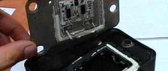
Ignition module
As mentioned above, the “ten” has 4 engine types: 16 and 8 valve internal combustion engines, as well as with a volume of 1.5 and 1.6 liters. This will lead to differences in the ignition modules. Depending on the installed engine with a certain volume, its own ignition module will be installed.
Differences
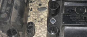
Differences in MZ: on the left 1.6 liters, on the right 1.5 liters 16 valves
The main differences between the modules will be the size and mounting holes. In a 1.5 liter internal combustion engine, the ignition module is larger in size in contrast to the 1.6 liter engine. The cost of the modules depends on the manufacturers, but it should be noted that the MZ from a 1.5 liter engine is always more expensive than a 1.6 liter one.
16 valve MZ
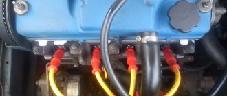
In a 16-valve internal combustion engine, the ignition module is installed on the valve cover near the oil filler neck.
8 valve MZ
The MZ on an 8-valve engine is installed on the front of the cylinder block between the dipstick and the breather.
Device
The ignition module has a common structure regardless of engine size. Inside the switch there are two high-voltage coils and an electronic circuit with many keys.
The coils are designed to switch high voltage and supply it to the spark plug to form a reliable spark in the combustion chamber of the engine.
The ignition module produces a spark in pairs, that is, each of the coils located inside the module is responsible for generating a spark on two cylinders: the first-fourth, the second-third.
- VAZ 2110 ignition module - check, replacement and repair
Symptoms of a problem
Based on some signs, it can be determined that the culprit of a malfunctioning internal combustion engine is the MZ. Below is a small list of symptoms indicating failure of the MH.
Signs:
- Failure of two cylinders at once, namely 1-4 or 2-3;
- Increased fuel consumption;
- Detonation at idle speed;
- The engine does not develop power;
- Difficult starting on a hot internal combustion engine;
These signs indicate a malfunction in the ignition system. These signs also apply to other possible breakdowns: spark plugs, wires and even injectors, but first of all you need to pay attention to the MH.
Possible malfunctions: signs and causes
Signs of a short circuit failure:
- when the driver presses the gas pedal, dips are felt;
- the power of the power unit decreases;
- the engine began to operate unstably at idle;
- the motor is shaking.
The main reasons why this can happen:
- Poor power supply in the car's electrical system. For normal operation of electrical components, a voltage in the on-board network of 11.5 volts is required. If the ignition wire is damaged or the battery performance is low, this may cause poor power supply. Accordingly, it will take more time to charge the short circuit.
- Mechanical damage to the device, for example, damage to the insulation. This problem may be caused by engine fluid entering the device through defective seals.
- Poor contact. Damage to the device, as well as constant exposure to moisture, can lead to failure of the primary and secondary windings, which in turn will contribute to the appearance of transition resistance. Such a malfunction can occur as a result of breakdowns in the washer system, washing the power unit, as well as heavy rain. Also, the structure of the device can be negatively affected by the salt that is sprinkled on roads in icy conditions.
- Thermal problems. Individual short circuits are more susceptible to high heat generation than others, which can also negatively affect the service life of the device.
- Working in vibration conditions. Due to high vibrations in engine operation, damage to the short-circuit structure may occur (video author - Resta channel).
Module check
After signs similar to failure of the ignition module appear, it must be checked before buying a new one, since its cost is not cheap.
There are three ways to check: substitution, visual inspection and a multimeter.
Substitution
The best and easiest way to check the MZ is to install another known good one from another exactly the same car. After which it will immediately become clear what the matter is and whether the Ministry of Health is to blame for this problem.
Visual inspection
It is necessary to inspect the module for chips, cracks, etc. There should be no damage to it. There should be no moisture or rust on the contact part.
Multimeter
Testing with a multimeter is carried out using the results of voltage and resistance measurements. This will help identify the cause of the failure of the module or its control circuit.
Step by step check
- Remove the power supply from the module. On the multimeter we set the DC voltage measurement limit to 20V. We turn on the ignition on the car and connect the multimeter contact on one side to the power block (namely to connector 15), and on the other side to the engine housing. The voltage between pin 15 and the motor housing must be at least 11-12V. Otherwise, the power supply circuit of the MH is faulty, or the battery is discharged.
- Next, we check the resistance on the VAZ 2110 ignition module itself. We set the multimeter to the resistance measurement parameter, namely 200 Ohms. We connect the multimeter probes to the high-voltage terminals of the MZ: 1-4, 2-3. The resistance of these coils, with a working MC, should be within 5 ohms.
- Then the resistance at the MC input is checked. One multimeter probe is connected to the central contact and the resistance is measured first on the leftmost contact and then on the rightmost one. The resistance should be in the 5 ohm range.
Cost and article
The table below shows the cost of the VAZ 2110 ignition module depending on the manufacturer and VAZ engine size.
- Checking the ignition module with a multimeter
| Engine volume | Manufacturer | vendor code | Price, (rubles) | |
| 1,6 | 8 | JSC SOATE | 2111-3705010-03 | 905 |
| 1,5 | 8 | BOSCH | F000ZS0211 | 2600 |
| 1,5 | 16 | StarVolt | 2112-3705010 | 1600 |
| 1,5 | 16 | Omega | 2112-3705010 | 1590 |
Typical module failures
If you have at least a little knowledge of electronics, as well as a multimeter, you can independently diagnose and identify the problem. Checking the VAZ-2110 ignition module will take a little time, but will save you from purchasing an expensive unit
Please note that sometimes races appear that disappear over time
Errors will remain in the microcontroller, so they can be read using special testers. But as practice shows, at a time when the faults do not manifest themselves, the tester cannot recognize error codes that were previously present but then disappeared. Very often, the cause of failures is dirt on the contacts, poor fastening of the case, lack of mass, and the presence of electrical interference.
Replacement
Replacement is quite simple and effortless. To replace, you will need a ratchet with an extension and a 10mm socket.
Replacement process
- We remove the negative mark from the battery, since the work is carried out on the electrical equipment of the car. This will avoid an unintentional short circuit in the vehicle's network.
- We remove the high-voltage wires from the MZ and the power connector.
- We unscrew the nuts securing the MZ and dismantle it.
- Installation is carried out in reverse order.
Pay attention to the order in which the wires are connected. Do not confuse them, otherwise the car engine will not start. Cylinder numbering starts from the timing mechanism from left to right. Connect the wires as it is written on the Ministry of Health.
We hope our article was useful to you.
The process of removing and installing the IKZ - replacing the ignition coils of a Lada Vesta car
Algorithm of actions:
- Remove the wire with the “–” sign from the battery and take the “TorX E8” or 8 key.
- remove engine protection;
- by pressing the locking element, disconnect the inductor from the block;
- pull out the coil by unscrewing the fastening.
Installation is done like this:
- Using a two-millimeter roller, apply a special high-temperature lubricant to the inner surface of the tips.
- install the IKZ in the reverse order of removal.
Replacing a part, as you can see, is a simple process. Using these methods, you don’t have to go to a car repair shop, and if a breakdown occurs at a long distance from service centers, you’ll have to deal with it yourself. Having studied the methods of checking faults, you will be able to fix the breakdown yourself.
We hope this article will help you in such a situation.
Ways to independently check the ignition module
Some gasoline engines that are installed on modern domestic and imported cars are equipped with ignition modules, which are a pulsed high-voltage current source. There are situations when these devices fail, leading to a complete or partial loss of performance of the car engine. Ways to check for a malfunction in the ignition module in a garage are covered in this article.
Design and principle of operation of the ignition module
Some old-school motorists call the modules double-spark coils, which makes sense. After all, the coil is the predecessor of the ignition module in the technical evolutionary chain. The module is a paired design consisting of two pairs of windings (primary and secondary) and a switch that alternately switches low-voltage current from one coil to another. In some models of double-spark coils, the commutator is structurally located outside the block.
The operation of the module is controlled from an electronic unit that collects and analyzes information from various working components of the engine. The block, unlike the classic coil, has 4 sockets for connecting high voltage wires going to the spark plugs. The pulse occurs in pairs, first at terminals 1 and 4, then 2 and 3. That is, each of the built-in coils is responsible for the operation of two cylinders. A spark occurs simultaneously, as a pair.
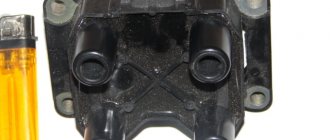
This is what one of the ignition module models looks like. The connector for connecting incoming wires is visible at the top.
At the input, the ignition module has a connector with four terminals. Usually most models have markings opposite them. Pulses from the Hall sensor alternately arrive at contacts A and B, serving as a signal to switch the commutator from one primary winding to another. C and D – ground and power supply (12 V), respectively.
Possible causes of failure
The weak point of the ignition coils and modules is the secondary winding, which generates a high voltage pulse. A coil break or breakdown may occur in it. The following factors lead to this phenomenon:
- use of low-quality or unsuitable candles;
- operation with non-functioning high voltage wires;
- frequent attempts to check the spark.
The high-voltage pulse arising in the secondary winding must be realized (spent). If this does not happen (if the integrity of a high voltage wire is broken, for example), a high-energy electrical pulse seeks an outlet. He will find it, with a high degree of probability, in the thin secondary winding.
- How to check the ignition module of a VAZ 2115 injector
Often, a module malfunction occurs when the integrity of poor-quality factory soldering of wires going to the switch elements is violated. This happens from vibration. Also, the cause of non-working coils can be a banal contact failure in the incoming connector. Another factor leading to a malfunction of the ignition unit is often moisture that gets on the device during washing or driving in unusual conditions.
Symptoms of a problem
It is extremely rare for two built-in coils to fail at once, so it is more likely to be possible to start the engine with a faulty unit. However, even an inexperienced driver will immediately suspect something is wrong. The malfunction will appear as follows:
- unstable (floating) idle speed;
- the engine has difficulty picking up speed;
- characteristic sound of the engine (triple);
- jerking when accelerating (while moving).
Operating a car with such a breakdown is possible (you can drive to a garage or car service station), but it is not advisable unless absolutely necessary.
Similar signs of unstable engine operation are possible with a number of other ignition or fuel supply faults. To differentiate possible breakdowns, the performance of the ignition unit should be determined. It would be useful to check the contacts of the wires coming to the device, as well as their integrity.
Checking module power
Before testing the performance of the coils, you should make sure that a possible breakdown is not caused by a loss of power to the device. First, you need to try to simply restore contact by moving it several times or disconnecting/connecting the block of wires included in the connector. If such manipulation does not lead to improved engine performance, a tester (multimeter) is used to determine the quality of incoming pulses.
The block of wires is removed from the connector. On the block, each terminal (A, B, C, D) has a corresponding socket. Testing with the engine running is done as follows.
- The first contact of the tester is in socket D, the second is to ground. The multimeter switch position is 20 volts. If there is power, the tester shows 12 volts.
- The first contact is in socket C, the second is ground. Switch on ohmmeter (20 Ohm). Normally it shows less than 1 ohm, that is, the mass is normal.
- The first contact is in socket B, the second is ground. 20 volt switch. The norm is not less than 0.3 volts. If this is so, it means that a normal pulse is coming from the Hall sensor to position B.
- Contact A is checked similarly to the previous one.
If such a check shows the norm, you need to test the module. If not, look for the cause in the electrical circuit to the coil.
Methods for diagnosing device performance
The simplest method that will help determine the performance of the coil is to replace it with a similar working device. This is possible if there is somewhere to get it. Please note that the module must match the parameters of the device under test. If the engine with a working coil works as before the breakdown, the ignition module is definitely faulty.
The main testing method involves using a multimeter. It consists in determining the resistance of the secondary windings of the coils built into the ignition module. The method is simple and does not require additional skills. The device does not need to be removed for testing. The check is done with the engine turned off.
This is how you check the resistance of the secondary winding with a multimeter
- High-voltage wires are removed from the module sockets.
- The tester switch is set to the 20 kOhm position.
- The multimeter rods are placed in turn in the recesses of the corresponding contact pairs (1 and 4, 2 and 3).
- With an intact secondary winding, the performance in both cases is the same. Normally, the resistance should be about 5.4 kOhm (in some models the indicators differ, which needs to be clarified). If the resistance is much greater, then there is a winding break. The resistance is much lower - a breakdown. The coil is faulty and cannot be repaired.
Video: How to check the secondary winding with a multimeter
When is there an option to repair?
If during testing both secondary windings show integrity and serviceability, the reason for the inoperability of the coils may be a break in the soldering of the switch wires. Such damage is detected when the rear cover of the module is removed. If you have a soldering iron and know how to use it, you can restore the integrity of damaged contacts, while at the same time strengthening the rest. This, unfortunately, is the only failure of the ignition module that can be repaired.
Testing the ignition module can be done using simple do-it-yourself instruments. Based on our advice, you will be able to fully check both the module itself and other elements of the mechanism that may be the cause of the breakdown. We wish you success in this matter!
Didn't find the information you are looking for? on our forum.
If you find an error, please select a piece of text and press Ctrl+Enter.
We recommend reading:
Installation of door cards from Priora on a VAZ 2110 VAZ 2111 the fuel pump does not work, causes of the malfunction How to change the stove on a VAZ 2109 -2115, replacement video The handbrake of a VAZ 2110 does not hold even after tensioning What kind of oil to pour into the steering gear of a VAZ 2107 Installing rings on the piston of a VAZ 2108 Brake lights on a VAZ do not light up 21099 injector reasons The wipers on the VAZ 2110 stopped working
Similar articles
What kind of oil to pour into the VAZ 2115 engine? Choosing oil for the VAZ 2110 VAZ color chart, codes, names, descriptions VAZ error codes - table with a list of all errors
Methods for checking the ignition coil with a multimeter for basic faults
The ignition coil is an integral part of the vehicle's starting system. Without it, it will not be possible to start the engine, whereas it is possible to start the engine without a battery, which also plays an important role in the formation of the first spark. The ignition coil is designed quite simply, but even it can become unusable due to various vehicle malfunctions or due to a factory defect. At the same time, when starting the engine, the operation of the ignition coil is not limited, and if it fails when the engine is already running, this will lead to its complete stop. Checking the ignition coil with a multimeter is a sure and easy way to determine the health of the unit and the need to replace it.
How to check the ignition coil
Checking the ignition coil is a three-step process that begins with preparation, then undergoes a visual inspection and ends with instrument testing. The unit can be checked on specialized diagnostic stands in dealer workshops or professional services. An independent check of the ignition coil is carried out using a multimeter - a universal diagnostic device with a wide range of applications.
Preparatory stage
Before proceeding directly to diagnosing the ignition coil, you need to acquire a multimeter (capable of determining voltage and electrical resistance, Ohms) and find technical documentation for the car. Various ignition coils are installed in cars, and the parameters of a specific model are written down in the car’s “passport”. If the car was bought second-hand, technical information about its units can be easily found on the Internet.
The ignition coil parameters required for its diagnosis are the resistance of the primary winding and the resistance of the secondary winding. If you were unable to detect them, you can rely on general numbers when testing the element, which will be discussed below.
Visual inspection of the ignition coil
The appearance of the ignition coil may vary depending on the model. At the same time, it has characteristic parts - a housing, a cover, two contacts and a central terminal. During a visual inspection, just look carefully at the body and look for chips, cracks or burnt areas on it. The body is made of hard rubber and does not allow current to pass through; in most cases, coil failure is due to internal damage.
Checking the ignition coil with a multimeter
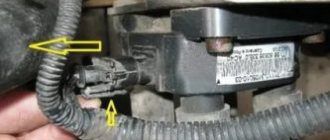
Diagnostics of the electronic engine control system and the electrical circuit of the distributor
The ignition coil is located in the distributor, and to check the voltage it is necessary to bend the latched clamp and remove the wires that go to it from the distributor. Next, you need to take a multimeter and set the parameters on it for measuring voltage. After this, one of the multimeter wires is applied to the terminal of the ignition coil, and the second to the car body (that is, to ground).
The result of such a measurement, with a working ignition coil, should be 12 Volts, displayed on the multimeter. If there are problems with the electronic engine management system or the electrical circuit of the distributor, the multimeter will show 0 Volts.
Checking the secondary winding for open circuit
To carry out such a diagnostic procedure, you need to set the multimeter to the mode for measuring electrical resistance (Ohms). Next, we connect one of the wires of the diagnostic device to the positive or negative terminal of the ignition coil, and the second to the central terminal.
If your measurement results in a value of about 6-8 kOhm, this is considered normal for most coils. Some can produce values up to 15 kOhm, which is also considered acceptable, but it is better to clarify this parameter in the technical documentation of the car. In the case where the deviations in the measured results are serious, in relation to the figures indicated in the technical documentation, we can talk about a break in the secondary winding.
Checking the primary winding for open circuit
The procedure for diagnosing the primary winding of the ignition coil is practically no different from checking the secondary winding. Again, take the multimeter, which is set to measure electrical resistance, and connect its wires to the positive and negative terminals of the ignition coil, that is, to the external contacts (in most cases).
If, as a result of the measurement, the multimeter shows values of about 0.5-2 Ohms, then there are no problems with the primary winding and it is operating normally. When the resistance differs from these values, the fact of a break in the primary winding is stated.
Purpose and principle of operation
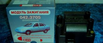
Ignition module VAZ 2110
The ignition module of a modern car performs the function of generating high voltage to produce a spark at the spark plugs. It consists of two coils with a closed magnetic circuit and a two-channel switch. Sometimes the switch is made as a separate device, but in most cases it is combined with an electronic control unit for the engine. Externally, the modules differ in the number of wires in the connection connector: a module with a switch has 4 wires, and paired coils have 3.
The ignition module is controlled by the ECU, which supplies constant voltage in the form of low-voltage control signals to the windings of its coils at the right moment. The end of the signal is the beginning of the spark. Thanks to magnetic induction, at the moment of application, a high voltage is generated, creating a spark at the spark plug. The device is located in the engine compartment and can be easily identified by the high-voltage wires leading to the spark plugs.
Ignition coils in the electronic circuit of Lada Priora
The ignition system on Priora differs from the usual traditional scheme of carburetor models. On old cars there was one ignition coil, and the direct distribution of impulses to the spark plugs was carried out by a distributor, which still needed to be configured correctly. On injection models of cars with electronic fuel injection, each cylinder has its own individual ignition coil, which sends an impulse to its spark plug for its cylinder.
The entire process is controlled by the ECU, an electronic on-board device, from which the signal goes directly to the short circuit. In order to correctly manage the injection process and timely send a signal to an electrical impulse, the ECU uses data from the following sensors:
- DPK - taking into account the position of the engine crankshaft, it supplies an impulse to the ECU;
- phase sensor - it signals the position of the camshaft, professionals call it a synchronization sensor;
- tachometer - from it a signal is sent to the ECU at what frequency the crankshaft rotates;
- Mass air flow sensor - by measuring air flow through the air filter, it determines the load on the engine at a given time;
- DTOZH - determines the engine temperature;
- DT is a knock sensor, its readings affect the ignition timing.
Under standard conditions, according to the ECU signal, the cylinders operate in the following cycle - 1 - 3 - 4 - 2. That is, the impulse for the spark arrives in those cylinders in which the compression cycle ends, before the valve opens, fuel is injected and a discharge occurs, detonation occurs and the cycle continues .
The ignition coil in the general ignition system plays the role of a low-voltage voltage converter from the on-board power supply systems, battery or generator, to high voltage. Specifically on the Priora, based on a signal from the ECU, it generates a high-voltage electrical pulse on the spark plug.
Ignition coil on PrioraStructurally, an individual ignition coil differs from a common short circuit:
- The primary winding, through which direct current flows, is located inside the secondary winding.
- There is an inner core inside the primary winding and an outer core around the secondary winding.
- High voltage, up to 40 kW, which is generated in the secondary winding, is transmitted to the spark plug not through high-voltage wires, as on carburetor cars, but through a tip, which consists of a high-voltage rod, a spring and a sheath that has insulating properties. In addition, there is a diode to quickly cut off a high-voltage pulse.
Individual ignition coils do not have any single, unified marking. Each manufacturer has its own designation system for electronic parts. Therefore, we must proceed from which short circuits are in greatest demand among Priora owners.
One of the most popular brands is BOSCH. These ignition coils are marked - 0 221 504 473 (also found 0 221 504 461). It is believed that such reels should cover 100 thousand kilometers without failure, although in fact this is not always the case.
Very often this happens due to the large number of counterfeit spare parts on the automotive market. Just ask how much an ignition coil costs for a Priora. The price of 1,150 rubles is not the highest, and they are sold in large wholesale for 850 rubles apiece. Of course, this is a tasty morsel for garage workshop dealers.
Interesting in this sense is the experience shared by one of the specialists who specifically studied this sensitive issue. He tells how the original IKZ differs from the fake one. He had a Priora and gave us examples of how to check the ignition coil:
- Under the casing there is a plastic housing.
- There is a “lightning” sign, as a designation of high voltage, near the mounting axle box.
- The surface of the plug is perfectly processed, the font on it is clear, it is applied using a laser, so minor melting is visible.
- The plant number is circled in an oval.
- The contact spring has tight coils made by the factory machine.
- The body is made of metal.
- The lightning bolt sign is missing.
- The surface of the plug is roughly processed, the inscriptions are stamped, the rubber tip lacks the date of manufacture, product number and Bosch brand name.
Signs of a malfunctioning ignition module
Checking the ignition module with a removed spark plug
A malfunction of the ignition module is determined by the following symptoms:
- Difficulty starting a cold engine due to lack of spark on one or more spark plugs.
- Floating engine speed at idle is a situation in which the speed changes without any action on the part of the driver.
- Dips in power, which manifests itself during acceleration and driving up a long climb.
- Decrease in engine power.
- Cylinders 1-4 or 2-3 do not work (engine “troits”).
- Indication of the “Check Engine” indicator.
Possible causes of ignition module malfunction
Despite the high reliability and durability of the ignition module, during operation it can fail, like any other mechanism. Among all possible causes of breakdowns, in 9 out of 10 cases the following occur and are diagnosed:
- Use of inappropriate components in the ignition system. High-voltage wires are selected based on the parameters of the module, since excessively high or low voltage creates malfunctions or burns out contacts.
- Defective or damaged parts, poor quality assembly. Defective components break down faster and damage other components or elements of the system. Practice shows that the selection of high-quality components and their periodic diagnostics allow the module to remain operational for a long time.
Checking the ignition module
Checking the ignition module for functionality is carried out in the following ways:
Replacing the ignition module with a known good one
1. The easiest way is to connect a known working module. In this case, the devices must be completely identical, the high-voltage wires are in good condition, and the reliability of the contacts has been checked.
Checking the contacts on the ignition module
2. Moving the module, which allows you to identify unreliable contacts. To do this, move the wire block and the module itself. If during exposure the engine reacts by changing its operation, then the cause of the problem lies in poor contact.
Measuring resistance at the terminals of the ignition module
3. Resistance measurement. To do this, you will need a tester switched to ohmmeter mode. Measurements are carried out on the paired terminals of the module between cylinders 1 and 4, as well as cylinders 2 and 3. The resistance value should be the same and approach 5.4 kOhm.
Checking the ignition module using a tester
4. Check the voltage with a tester. One probe of the device is applied to contact A of the block, the second to ground. After turning on the ignition, take readings from the device. If the wire is in good condition, it will show a voltage of 12 V; if it is missing, check the fuse protecting the ignition module. Then check the continuity of the circuit with a 12 V test lamp. Apply one end of the wire to contact A and rotate the starter. If the lamp does not blink, the circuit is broken. The procedure is repeated in a similar way with other contacts.
Diagnostics of the ignition module with professional equipment
5. Diagnostics at a service station by connecting a computer with special software to the computer. Malfunctions are detected in the form of errors indicated by an alphanumeric code, after which a more in-depth diagnosis of the malfunction is carried out to make a decision - repair the ignition module or replace it. A similar check is carried out at a specialized service station using an oscilloscope.
Repair
Ignition module VAZ 2107
The design of the ignition module is quite complex: it includes one or more coils, a board, contacts and wires. Of all the above elements, only contact connections can be repaired; in some cases, replacement of parts (transistors, coils) is possible.
The module is dismantled and opened for repair purposes. For this you will need:
- Socket wrenches with heads 1, 13 and 17.
- Hexagon 5.
- Screwdriver.
- Soldering iron.
- Flux for aluminum.
- Stranded wire.
- Nail polish.
Opening the ignition module
Repair of the ignition module is carried out in the following order:
- On the removed device, open the case by prying it off with a screwdriver.
- Remove the silicone film covering the board.
- All aluminum is removed from the explosive contacts.
- On the board, new wires are soldered in place of all the dismantled old ones. To do this, the surface of the collector is cleaned of deposits, after which the board is heated to 180°C (a characteristic smell will indicate when the desired temperature has been reached). During the soldering process, the ends of the wires are connected to the module.
- At the end of the operation, all contacts, the board and the module are covered with nail polish.
- The device is assembled in the reverse order, installed on the car and the engine is started. In case of normal operation, the ignition module is sealed tightly with sealant, while the wires are tucked inside the cavity so that they are not pinched at the edges by the plate.
If the device does not work, then a breakdown inside the module should be looked for more carefully. The transistor, electronic component may have failed, or there may be a break in the coil. Such a repair makes sense only if its price is significantly lower than the cost of a new part.
VAZ-2110 engines with a two-shaft head with 16 valves are built on the basis of the old one and a half liter VAZ 21083 engine. Changes affected only the cylinder head and air supply system. Twin-shaft 16-valve engines were installed in two types - a 1.5-liter engine (VAZ-2112) and a 1.6-liter engine (VAZ-21124). The ignition system on these engines is different. Today we will look at the ignition module for the injection 16-valve engine 2112 and find out its differences from the 1.6-liter engine 21124.
Design of the ignition module of a 16-valve engine on a VAZ-2110
Despite the similarity in engine design, the ignition system of the 1.5-liter injection 16-valve engine differs from the 1.6 16-valve engine. The 1.6 liter engine uses an electronic contactless ignition system with individual coils on each spark plug. Therefore, there was no need for an ignition module. Such a system is more reliable and cheaper to operate, since if one coil fails, there is no need to replace the entire module.
This is the coil that sits on each spark plug of a 1.6 liter engine.
Features and articles
The 16-valve 1.5-liter VAZ 2112 injection engine used the same non-contact ignition system as the eight-valve engine, but a different ignition module was installed.
Its catalog number is 2112-3705010 , and they sell it for 2000-3000 rubles , depending on the manufacturer. The design of the module remains the same - two ignition coils (for cylinders 1-4 and 2-3) plus switch keys in a single block. The spark is supplied to the cylinders in pairs using the idle spark method. This means that sparking occurs in two cylinders simultaneously - in one on the compression stroke (working spark), in the second on the exhaust stroke (idle spark).
Ignition module for 16-valve 1.5 liter engine.
Video “Recommendations for diagnosing MH”
Important recommendations and features of diagnosing MZ in VAZ 2112 cars are shown in the video below (author - AutoElectrika Diary channel).
The car jerks, there is no traction, vibration is felt, or the engine is rough; all these are symptoms of improper operation of the individual ignition coil (IIC). Other signs of a faulty ignition coil are the presence of errors 0301, 0302, 0303 and 0304, indicating misfire in one of the cylinders. Let's look at a few simple ways to check the ignition coil with your own hands.
It is worth noting that the process of checking IKZ on modern Lada cars (XRAY, Vesta, Largus, Granta, Kalina and Priora) does not have significant differences. All actions are performed in the same way.
Symptoms of module malfunction
Signs of a faulty ignition module on a VAZ-2110 are always acutely felt:
- hesitant engine starting or failure to start;
- failures during sudden changes in speed;
- high fuel consumption;
- two cylinders do not work, the engine is feverish;
- lack of dynamics;
- a sharp drop in power;
- drop in power and thrust after warming up.
Other faults
We unscrew and look at the spark plugs. Checking the high voltage wires.
These symptoms may not only be caused by the ignition module. To determine the malfunction, it is enough to spend a few minutes diagnosing spark plugs, high-voltage wires and caps. This will eliminate the remaining elements of the ignition system and make sure that it is the ignition module that is faulty.
- Checking the spark plugs . To do this, unscrew them, put on the caps, place them on the cylinder head and crank the engine with the starter. The spark should be stable on all spark plugs. We replace non-working spark plugs and repeat the test. Under no circumstances should you crank the engine with the starter with the high-voltage wires removed. This will lead to a breakdown in the ignition module cover.
- Checking the high voltage wires . We remove the caps and hold the wire contact through the insulator at a distance of 10-15 mm from the head . With good wires, the spark should pierce this distance vigorously and confidently. Next we check the wires for resistance. A working wire should have a nominal resistance of 7-10 kOhm. Any deviation from this value indicates the need to replace the entire set of high-voltage wires.
- We check the caps for breakdown .
We also look at the block and especially the wires included in it.
If all these elements are in good condition, the ignition module must be checked.
In addition, it is better to check the spark plugs and wires on a warm engine, since a half-dead ignition module can operate cold for some time and fail when heated. You also need to be sure that all sensors are working properly. This can be indicated by an error code or Check Engine light.
Algorithm for checking the ignition module on a VAZ-2110
We begin the test with the block connected to the module.
To check the module, we only need a multimeter and it will take 15-20 . This is quite simple to do, the main thing is to adhere to the algorithm and know the nominal values of the working module:
- We check the power supply and the presence of pulses supplied from the ECU . We check the power between the central terminal (15) of the wire block connected to the module and the engine ground. When the ignition is on, the voltage should not be less than 12 V. Otherwise, either the battery is dead or the ECU does not work.
- We check the pulses from the ECU on the wiring block . We install one tester probe on connector 15, the second on the far right, then on the far left. The assistant cranks the engine with the starter, and at this time we record short-term voltage surges with a tester. If there are no impulses from the ECU, it is he who is to blame.
- We check the resistance on the secondary windings of the coils . We put the tester in resistance measurement mode and measure it at the high-voltage terminals of the module cover. Between pins 1 and 4 and pins 2-3, the resistance should be 5.4 kOhm. Otherwise, the module must be replaced.
- We check the resistance of the primary windings between contacts 15 and the rightmost, then the leftmost terminals. Nominal - 0.5 Ohm . Deviation is not allowed.
- Check the module for a short circuit . In ohmmeter mode, install one multimeter probe on the central terminal, the second on the metal body. There shouldn't be any resistance. If the device detects at least some resistance (other than unity or infinity), the module must be replaced.
Video about checking the ignition module
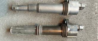
The ignition coil, which is located in the car, essentially converts the low voltage from the battery and generator into high voltage, to supply it individually to each spark plug. Roughly speaking, this is a miniature electrical transformer, the moment of failure of which is almost impossible to predict and repairs and diagnostics have to be carried out on the failed device. Below in our article we will tell you in detail how to check the ignition coil for a VAZ-2112 with your own hands.
The video describes in great detail the algorithm for checking the ignition coil on a VAZ-2112:
How to check the ignition coil? Replacing the ignition coil of a VAZ 2107
A little theory.
The ignition coil on cars is necessary to convert a low voltage current of 12 V into a high current - 11-20 kV, which is necessary to create a spark at the spark plugs. What happens next is probably known to everyone!? The spark ignites the working mixture and a release of energy occurs, which sets the pistons in motion. As I said in my previous articles, the ignition coil is a kind of transformer, which can also be called a miniature automotive “substation”.
On the “seven”, as a rule, contact ignition systems of the B-117 A type are used. The coil itself is located in the engine compartment and is attached to the left mudguard with two studs. Also found on the VAZ 2107 are non-contact ignition systems (BSZ), in this case, coils of type 27.3705 are used, oil-filled with an open magnetic circuit, as well as type 3122.3705 dry coils with a closed magnetic circuit.
Ignition coil device
It is known that on 8-valve engines an ignition module was used (module repair, diagnostics) with two channels and coils that are capable of transmitting a spark to a pair of spark plugs at once. However, on a 16-valve engine, the coils became individual for each spark plug.
Prices and articles
The ignition coil from the Russian manufacturer SOATE for the VAZ-2112 has article number 2112-3705010-12 and costs around 1,000 rubles . Analogs from Bosch can cost twice as much, but the quality of these parts is much higher. In any case, the choice is always yours.
Ignition coil from Bosch.
A little about prices
We have already noted which switch and transistor are used when repairing the ignition module of a dozen. The first costs about 3 dollars, and for the second you will have to pay about 6 dollars.
Some craftsmen use a domestic analogue of the transistor - model KT848A. Of course, it costs less. But its problem is its lower quality and larger size, which somewhat complicates the repair process.
We recommend watching:
- Replacing high-voltage wires Kalina 8 valves
- After warming up the engine runs intermittently
- Zil 130 shoots into the carburetor reasons
- Expiration date of spark plugs
- Why doesn't the starter start?
- Why does the car jerk at high speeds?
The process of checking all ignition coils on a VAZ-2112
The VAZ-2112 engine with 16 valves uses individual Bosch ignition coils and in order to check them, the following procedure must be followed:
- First of all, we remove each coil from its landing well.
The order of dismantling does not matter. - Then we turn off the power supply and remove them all together as an assembly.
- First of all, we pay attention to its external condition, the absence of cracks and various breaks.
If it is damaged, replace it - The same applies to the spring located inside the coil, look at its position, it should be exactly in the center.
Let's look at its correct location
Despite the fact that many people on the Internet talk about the impossibility of checking a coil with their own hands, it is possible to check it only by knowing their initial values, which are measured in ohms .
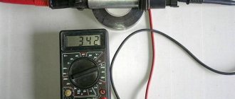
- In order not to make false measurements, first of all we check the internal resistance of the wires and the multimeter itself .
To do this, switch the device to the OM position and connect the probes to each other. What value the multimeter gives is its internal resistance. The value can range from 0.0 to 0.3 ohms. On the multimeter, a value of 00.3 Ohm is normal. - First of all, we “ring” the primary winding, which is located on the first and third contacts; when connecting, the polarity does not matter.
- Depending on the presence of error readings and coil readings, we add up the final indicators.
For example, if the internal resistance is 0.2 ohms and the coil value is 0.7 ohms, therefore the correct value would be 0.5 ohms. Which is the norm. The value of 00.8 ohms is subtracted from the resistance of the multimeter and we get 00.5, which is the norm. - We continue diagnostics with each of the coils.
- If it happens that there are no indications, then we once again check the quality of the connections and the correctness of the connection. If the readings are still zero, then the primary winding on this coil is faulty.
When the readings on the primary winding on all coils are correct and show their values, we proceed to checking the secondary winding.
- To do this, set the switch to 2000 kOhm mode.
- Next, we place the multimeter probe on the coil, observing the polarity, black to pin 2, which is located exactly in the middle of the connector, and the red probe to the spring, inside the rubber plug.
- Three-digit values will mean the coil is working properly, and infinity values will indicate its failure.
Such designations indicate the serviceability of the ignition coil.The number “1” stands for infinity and indicates a faulty ignition coil.
- Please note that if you cannot measure the resistance correctly the first time, you can wipe the fixed elements from dirt and deposits, since dirty parts can interfere with the signal output.
- When replacing old coils with new ones, you should strictly use analogues, taking the faulty part with you to the store in advance.
Checking the ignition coil of VAZ 2104, 2105, 2107 cars
The ignition coil on VAZ 2104, 2105, 2107 can be checked without removing it from the car.
However, for a complete inspection of the coil, it is necessary to remove it from the engine compartment and clean it of dirt, rinse it with white spirit or kerosene.
We will check the appearance of the coil and the presence of a “break” and short circuit in its primary and secondary windings (a multimeter or autotester is required).
Checking the ignition coil of VAZ 2104, 2105, 2107
— Check the appearance of the ignition coil
We inspect it for mechanical deformation, cracks in the cover, and oil leaks. We replace the coil that is deformed or has oil stains; the crack in the cover can be cleaned and filled with epoxy glue.
— We check the primary winding of the ignition coil 2104, 2105, 2107 for an open circuit
We connect the probes of a multimeter or autotester in ohmmeter mode to the side terminals of the coil. See photo above.
Resistance of a serviceable primary winding at a temperature of 20 degrees. should be:
3 - 3.5 Ohm (coil B-117A)
0.45 - 0.5 Ohm (coil 27.3705)
0.57±0.05 Ohm (coil 3122.3705).
— We check the secondary winding of the ignition coil 2104, 2105, 2107 for an open circuit
We connect the probes of a multimeter or autotester in ohmmeter mode: one to the side terminal “+B” of the coil, the other to its central high-voltage terminal.
Checking the secondary winding of the ignition coil for an open circuit
Resistance of a serviceable secondary winding at a temperature of 20 degrees. should be:
7.4 - 9.2 kOhm (coil B-117A)
4.7 - 5.5 kOhm (coil 27.3705)
6.5±0.65 kOhm (coil 3122.3705).
— Check the windings of coils 2104, 2105, 2107 for a short circuit
We connect the probes of a multimeter or autotester in ohmmeter mode: one multimeter probe to the “+B” terminal of the coil, the other to its body. Resistance should tend to infinity.
Checking the ignition coil for a short circuit
If deviations in the multimeter readings from the norm are detected, replace the ignition coil with a new one.
Notes and additions
— A malfunction of the ignition coil leads to the following problems in the operation of the car engine and its systems: the engine does not start, the engine starts and stalls, the engine “troubles.” Their reasons are either a decrease in the energy of the high-voltage current generated by a faulty coil (the spark on the candles is weak), or a complete cessation of its production of this very current.
TWOKARBURATORS VK -More information on the topic in our VKontakte group