Ignition module
As mentioned above, the “ten” has 4 engine types: 16 and 8 valve internal combustion engines, as well as with a volume of 1.5 and 1.6 liters. This will lead to differences in the ignition modules. Depending on the installed engine with a certain volume, its own ignition module will be installed.
Differences
The main differences between the modules will be the size and mounting holes. In a 1.5 liter internal combustion engine, the ignition module is larger in size in contrast to the 1.6 liter engine. The cost of the modules depends on the manufacturers, but it should be noted that the MZ from a 1.5 liter engine is always more expensive than a 1.6 liter one.
16 valve MZ
In a 16-valve internal combustion engine, the ignition module is installed on the valve cover near the oil filler neck.
8 valve MZ
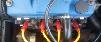
The MZ on an 8-valve engine is installed on the front of the cylinder block between the dipstick and the breather.
How to check the malfunction of the VAZ 2114 ignition module on your own?
The easiest way to check the device without removing it is to diagnose it at the moment the power unit is tripped. When the motor begins to operate unstably, it is necessary to disconnect the connector elements from each component of the module one by one. If the connector is disconnected from a functioning device, the operation of the engine will change. Dips will appear, and the unstable operation of the unit will increase. When the non-working element of the MH is disconnected, the motor will operate in the same way.
There is another simple diagnostic method, its principle is as follows:
- You will need an assistant to check. The spark plug is removed from the seat. The high-voltage cable is disconnected from the device.
- Then the disconnected wire is connected to a spark plug, which is applied to the body of the power unit.
- The machine motor is starting, you need to make sure that a spark hits the spark plug. If it passes, a blue light will appear between the device and the surface of the power unit, its formation is accompanied by a crackling sound. If there is no spark, then the spark plugs, high-voltage cable and module must be diagnosed.
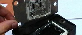
Device
The ignition module has a common structure regardless of engine size. Inside the switch there are two high-voltage coils and an electronic circuit with many keys.
The coils are designed to switch high voltage and supply it to the spark plug to form a reliable spark in the combustion chamber of the engine.
The ignition module produces a spark in pairs, that is, each of the coils located inside the module is responsible for generating a spark on two cylinders: the first-fourth, the second-third.
HOW TO SET THE IGNITION
Ignition timing directly affects the performance of the vehicle. From the correctness of the settings...
The correct functioning of the ignition module not only has a significant impact on the start of the vehicle’s power plant, but also ensures the stability of its operation in all modes. To carry out a complete diagnosis of this electronic device, you need quite complex equipment, available only in large specialized workshops. However, you can check the functionality of the ignition module yourself in an amateur garage. The only logistical support for this test will be a multimeter, or tester.
The first and simplest way to determine the functionality of the ignition module is to replace it with a known-good device.
Attention! When using a donor car for testing, do not forget that only the first Lada Samara models were equipped with the ignition module, as a separate device. Machines of later releases are equipped with separate type devices (the switch is included in the electronic control unit).
The procedure for replacing the ignition module includes the following steps:
- Preparation of the necessary tools: wrench 17 (open-end), wrench 13 (open-end), wrench 10 (socket), hexagon.
- De-energizing the vehicle by disconnecting the “-” terminal from the battery.
- Removing the wire block.
- Disconnecting high voltage wires.
- Unscrewing the fastenings to the power unit.
- Recess of the ignition module (unscrews from the holder using a hexagon).
Installing a replacement module involves connecting high-voltage wires (the module body contains hints). In addition, the wire terminals also have corresponding designations. We install the ignition module, performing the manipulations in the reverse order, followed by checking its functionality.
Symptoms of a problem
Based on some signs, it can be determined that the culprit of a malfunctioning internal combustion engine is the MZ. Below is a small list of symptoms indicating failure of the MH.
- Failure of two cylinders at once, namely 1-4 or 2-3;
- Increased fuel consumption;
- Detonation at idle speed;
- The engine does not develop power;
- Difficult starting on a hot internal combustion engine;
These signs indicate a malfunction in the ignition system. These signs also apply to other possible breakdowns: spark plugs, wires and even injectors, but first of all you need to pay attention to the MH.
Module check
After signs similar to failure of the ignition module appear, it must be checked before buying a new one, since its cost is not cheap.
There are three ways to check: substitution, visual inspection and a multimeter.
Substitution
The best and easiest way to check the MZ is to install another known good one from another exactly the same car. After which it will immediately become clear what the matter is and whether the Ministry of Health is to blame for this problem.
Visual inspection
It is necessary to inspect the module for chips, cracks, etc. There should be no damage to it. There should be no moisture or rust on the contact part.
Multimeter
Testing with a multimeter is carried out using the results of voltage and resistance measurements. This will help identify the cause of the failure of the module or its control circuit.
Step by step check
- Remove the power supply from the module. On the multimeter we set the DC voltage measurement limit to 20V. We turn on the ignition on the car and connect the multimeter contact on one side to the power block (namely to connector 15), and on the other side to the engine housing. The voltage between pin 15 and the motor housing must be at least 11-12V. Otherwise, the power supply circuit of the MH is faulty, or the battery is discharged.
- Next, we check the resistance on the VAZ 2110 ignition module itself. We set the multimeter to the resistance measurement parameter, namely 200 Ohms. We connect the multimeter probes to the high-voltage terminals of the MZ: 1-4, 2-3. The resistance of these coils, with a working MC, should be within 5 ohms.
- Then the resistance at the MC input is checked. One multimeter probe is connected to the central contact and the resistance is measured first on the leftmost contact and then on the rightmost one. The resistance should be in the 5 ohm range.
How to check input wires for serviceability
Following the recommendations of specialists, to check the condition of the wires at the input, they need to be “ringed”. What does it mean?
- Determine the operating format of the multitester in the voltmeter position, and then disconnect the wiring block from the VAZ-2114 ignition module.
- Focusing on contact A, mount the first dipstick, and fix the second one to the engine ground.
- Ask an assistant to start the car or, alternatively, crank the starter. At this time, your task is to observe the measurements on the display. Normal voltage is 12 volts.
- Carry out exactly the same actions with the remaining contact.
What to do if there is practically no voltage? Then evaluate the serviceability of the fuse - it is likely that it has blown. Find 3 safety mechanisms on the VAZ-2114 electronic control panel. So, the third 7.5 A is a device suitable for the car module.
Even if the fuse is intact and intact, there is a possibility of oxidation and wire breakage, as well as loose contacts.
What to do if there is no multitester available? A control light designed for 12 V will help solve the problem. One wiring of the lighting device is placed to the contact of the block, and the other is closed to the motor housing. After turning on the ignition, the light should flicker.
How to check the VAZ-2114 ignition module with your own hands is shown in the video instructions:
Cost and article
The table below shows the cost of the VAZ 2110 ignition module depending on the manufacturer and VAZ engine size.
| Engine volume | Number of valves | Manufacturer | vendor code | Price, (rubles) |
| 1,6 | 8 | JSC SOATE | 2111-3705010-03 | 905 |
| 1,5 | 8 | BOSCH | F000ZS0211 | 2600 |
| 1,5 | 16 | StarVolt | 2112-3705010 | 1600 |
| 1,5 | 16 | Omega | 2112-3705010 | 1590 |
We check the ignition module on the injection VAZ-2110 8 valves with our own hands
At different times, different engines were installed on the VAZ-2110 car, both carburetor and injection. However, regardless of the type of power system and the number of valves (8 or 16), all engines are assembled on the unit base of the old engine 21083 and 21093. The most progressive of these engines is the 16-valve 1.6-liter VAZ 21124 engine with a power of 89 horsepower. Today we will touch on the ignition module for 8-valve engines 2111 and 21114 (1.6 l), check its performance and find a suitable replacement for the failed module.
Getting to know the device
A multimeter for checking the ignition module, spark plugs, starter, parking sensors or other devices is a combined electrical measuring device that includes several options. The minimum set of the spark plug tester includes the options of a voltmeter, ohmmeter, and ammeter. In some cases, the device can be made in the form of current measuring leads.
Designation of all elements of the device
On sale you can find both analog and digital devices for diagnostics. By its design, the device can be portable, used for basic diagnostics and fault detection. Or it could be a complex device with many different capabilities.
Version of the module on the 8-valve VAZ-2110
The top ten was equipped with two 8-valve engines of different sizes - 1.5 (2111) and 1.6 liters (21114). The ignition modules for these engines are different.
- The one and a half liter engine has a module with article number 2112-3705010,
- and the 1600 cc is equipped with module 2111-3705010.
A module for a 1.5 liter engine costs about 1500-2100, and the second one is 500 rubles cheaper.
Which is better?
SOATE devices manufactured in Stary Oskol have proven themselves to be the most reliable ignition modules.
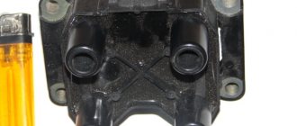
Module structure
The module consists of two ignition coils and two high-voltage switch switches.
Inside the module there is a board with radio components and ignition coils filled with compound.
The coil generates a high voltage pulse, and it is a simple transformer with two windings, primary (induction voltage about 500 V) and secondary (induction voltage at least 20 kV). All this is assembled in a single housing, on which there is a connector for signal wires (from the engine control unit) and four terminals for high-voltage wires.
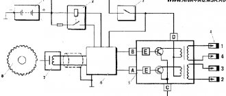
Schematic diagram of the module.
The module operates on the principle of an idle spark - it distributes sparks in pairs to cylinders 1-4 and 2-3 according to impulses transmitted from the ECU.
Methods for diagnosing device performance
The simplest method that will help determine the performance of the coil is to replace it with a similar working device. This is possible if there is somewhere to get it. Please note that the module must match the parameters of the device under test . If the engine with a working coil works as before the breakdown, the ignition module is definitely faulty.
The main testing method involves using a multimeter. It consists in determining the resistance of the secondary windings of the coils built into the ignition module. The method is simple and does not require additional skills. The device does not need to be removed for testing. The check is done with the engine turned off.
This is how you check the resistance of the secondary winding with a multimeter
- High-voltage wires are removed from the module sockets.
- The tester switch is set to the 20 kOhm position.
- The multimeter rods are placed in turn in the recesses of the corresponding contact pairs (1 and 4, 2 and 3).
- With an intact secondary winding, the performance in both cases is the same. Normally, the resistance should be about 5.4 kOhm (in some models the indicators differ, which needs to be clarified). If the resistance is much greater, then there is a winding break. The resistance is much lower - a breakdown. The coil is faulty and cannot be repaired.