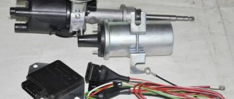
First of all, let's get acquainted with the ignition system of the GAZ-3307 truck. The ignition system of the GAZ-3307 is battery-based, contactless transistor with a voltage in the primary circuit of 12V, consists of electric current sources, an ignition coil, an additional resistor (if I’m not mistaken, where since 2000 they have been produced without an additional resistor), a switch, an ignition distributor, spark plugs, plug tips, ignition switch and low and high voltage wires.
Technical characteristics of the ignition system of GAZ-3307 (GAZ 53) cars
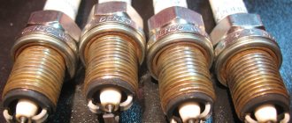
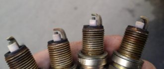
Ignition order of GAZ-3307 1 - 5 - 4 - 2-6 - 3 -7 - 8 Type of ignition distributor (distributor) - 24.3706 Distributor shaft rotation speed per 1 min with uninterrupted spark formation when working with a B116 ignition coil on a three-electrode spark gap at spark gap 7 mm, min-1 - 20 - 2300 Direction of rotation of the ignition distributor roller (distributor) GAZ-3307 - clockwise Ignition coil GAZ-3307 - B116 Spark plugs - A11 Spark gap size in spark plugs, mm - 0.8 - 0.95 Additional resistor - 14.3729 Switch - 131.3734 or 13.3734 Spark plug tip - 35.3707200
Diagram of the GAZ-3307 ignition system
And so, as I already said in our time, the ignition system of the GAZ-3307 truck has undergone minor changes.
As I already wrote, this happened after 2000, this is approximately what I am saying. I can’t say for sure, I’m afraid I’ll make a mistake, but I didn’t bother googling and searching for it; I just don’t have time for it and it’s not particularly interesting. If you are interested, look for it and then share it with me. You can leave a comment.
This applies to transistor switch brands 13.3734 and 131.3734
You can see the difference is just one number, that is, it was 13.3734 before 2000, but they began to produce the GAZ-3307 after 2000 with a switch of 131.3734. And so there is only one number and this is one number, that is, as you noticed, number 1 removes the additional resistor from the GAZ-3307 ignition system - 14.3729.
That is, simply put, the function of the additional resistor is 14.3729. built into the transistor switch 131.3734.
I want to warn you, someone may say “yes, I put brand 13.3734 instead of brand 131.3734 and why doesn’t the machine work?” I agree with him.
GAZ-3307 will of course work and go normally, but not far. Why, you ask, of course, and you will be right, you need to find out why ? Yes, because your ignition coil (bobbin) will simply burn out.
Why this will happen : The ignition coil, GAZ-3307 (B 116) is a transformer, on the iron core of which the secondary winding is wound, and on top of it is the primary winding. The core with windings is installed in a sealed steel case filled with oil and closed with a high-voltage plastic cover.
Operating temperature from -50° C to +80° C. Resistance value at a temperature of 25° C: primary winding (0.65+0.07) Ohm, secondary winding (18+1.8) kOhm.
Developed secondary voltage 18 kV max. Supply voltage 12 V. Weight 0.95 kg. During operation, the B-116 ignition coil is supplied with reduced voltage through an additional resistor-14.3729 . The resistor heats up during operation, this is normal. The resistor, when the starter is turned on (when starting the engine), is bypassed and the coil is supplied with full voltage (more precisely, the on-board voltage supplied by the starter), this makes starting easier.
the additional resistor 14.3729 takes up “work” again . And now give yourself this picture of a GAZ-3307, well, let’s say after the year 2000, there is, of course, ignition without an additional resistor - 14.3729 and an ignition coil B-116 and a transistor switch 131.3734, and you took and installed a transistor switch 13.3734, and what next GAZ-3307 Of course, it will start; moreover, it will drive normally (as I already stated above), but the coil will not burn out very far. That is, there is no one to lower the on-board voltage for the ignition coil.
And as we already know, the B-116 ignition coil is powered by a reduced voltage through an additional resistor-14.3729 or with an added voltage reduction function in a transistor switch brand 131.3734.
And as a result, the B-116 ignition coil will simply burn out.
I still cannot help but note this moment. There is also a B-114 ignition
As you noticed, it looks no different from the B-116 (some people use it), it also fits the GAZ 3307, but I personally do not advise you to use it. GAZ-3307 will of course work (I checked it myself; I had to drive home B-114 ignition the B-116 burned out). If you put it on and drive it, you may not feel the difference, but in the end it will affect fuel consumption (increase )and of course the car’s traction (decreased), the engine will run unstably. Simply, the B-114 ignition coil is designed for GAZ-53 with a contact-transistor ignition system
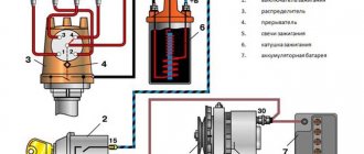
Connection diagram for the new ignition system. Switch 131.3734.
1. Candles; 2. Anti-interference resistance; 3. Distributor; 4. Switch; 5. Ignition coil; 6. Generator; 7. Fuse; 8. Battery; 9. Ignition switch.
Read also: Is it possible to put a child seat in front?
Connection diagram for switch 131.3734 as part of the ignition system:
Wiring diagram for the old-style ignition system. Switch 13.3734.
1. Distributor; 2. Switch; 3. Additional resistor (variator); 4. Ignition coil.
You can familiarize yourself with the contact-transistor ignition system in this article:
Contact-transistor ignition system of GAZ-53.
And so, friends, you and I, I think, have finished familiarizing ourselves with the ignition system of the GAZ-3307 (GAZ-53) truck. If you suddenly have any questions, you can leave comments.
Now let's figure out what are the reasons for the lack of a spark.
If suddenly you haven’t found something, or you simply don’t have time to search, then I recommend reading the articles in the “ GAS Repair ” categories. I am sure you will find the answer to your question, and if not, write in the comments the question you are interested in, I will definitely answer.
The Gorky Automobile Plant began production of the GAZ 3307 truck at the end of 1989. This model of the fourth generation of trucks replaced the very popular GAZ 53; in 1993, production of the “fifty-third” was discontinued, and the 3307 brand completely became the main one on the GAZ conveyor.
Early GAZ 3307 truck
Diagram of the ignition system for GAZ 3307 cars
The ignition system is one of the most important systems of a car equipped with a gasoline internal combustion engine. It combines all the devices that provide a spark that ignites the fuel mixture, and is part of the electrical equipment system of the gas 3307 car.
Ignition system design
The ignition system of the GAZ 3307 has a fairly simple structure, typical of ignition systems that use an external power source - a battery.
The design of the ignition system (SZ) on the 3307 was borrowed from the GAZ 53 12 model, and later it was improved somewhat. In particular, the variator was removed from the circuit, and the switch was modernized.
Ignition system components 3307
It includes the following elements:
- Accumulator battery. It is a source of constant low voltage voltage;
- Ignition switch with key. When turned on, it provides a constant voltage in the low-voltage circuit;
- Ignition coil. This element is necessary to convert low voltage to high voltage (used as a step-up transformer);
- Breaker-distributor (or distributor);
- Switch;
- Variable speed drive. Used in earlier versions of the contactless ignition system, it is absent in later versions;
- High voltage wires;
- Tips of high-voltage wires.
Return to contents
Connection diagram of the coil and switch and variator
The distributor itself may periodically fail, but this does not happen so often.
Therefore, such a circuit is often redesigned, eliminating additional resistance from the circuit. Turning on the ignition, remove the connector from the Hall sensor and measure the voltage between the outer contacts and check the power supply to the sensor.
When checking, the second end of the test light wire is connected to the body by ground. Starter In addition to the battery, the ignition system also includes other units. How to check the ignition coil
The main purpose of the transistor switch TK is to turn on and off the low voltage current in the primary winding of the induction coil. We measure the resistance between any of the contacts and ground - there should be no resistance. At the moment the breaker contacts open, the current in the transistor control circuit disappears and the resistances of the emitter and collector junctions increase sharply, while the transistor turns off and turns off the current in the primary winding of the induction coil. Emergency vibrator fig. So, briefly about the principle of operation. When connecting the coil to the car’s ignition system, in principle, you should not have any difficulties if, during preliminary dismantling, you marked or remembered which wires are connected where. But not everyone will be satisfied with the price, and it can be difficult to buy - you won’t find it in every city.
Operating principle of the ignition system 3307
The operation of the ignition system 3307 is built according to the classical scheme. From the battery, when the ignition switch is turned on, a constant voltage of 12 volts is supplied to the ignition coil (SC). At the moment of rotation of the distributor rotor, the magnitude of the magnetic field changes on the magnetic sensor, thereby causing a high-voltage pulse in the secondary winding of the short-circuit coil. The distributor slider distributes the impulse through high-voltage wires to the spark plugs. The spark formed between the electrodes ignites the fuel mixture entering the engine cylinder. The engine cycle is in progress.
Read also: Ignition timing at idle
Ignition system components 3307
Accumulator battery
The manufacturer provides the 6ST-75 as a battery, modifications of which are available from many domestic manufacturers. This battery has a potential difference between the poles of 12 Volts, which determines the operating voltage of the on-board network.
The standard GAZ 3307 battery is considered to be a 6ST-75 battery.
Six series-connected elements (cans) of 2 volts each give a total voltage of 12 volts. The nominal battery capacity is 75 ampere-hours. The starting current can be from 640 to 750 Amps depending on the model.
The cost of a new battery depends on the manufacturer and ranges from 3-5 thousand rubles; a used one can be purchased much cheaper.
Starter
In addition to the battery, the ignition system also includes other units. The 230-A1 starter, which is used in a very large number of equipment based on GAZ vehicles, is directly involved in the appearance of the first spark.
This is what a starter for a GAZ 3307 looks like
Egnition lock
The GAZ 3307 ignition switch is designed to turn on and off the ignition circuit, as well as other energy consumers. It has four positions, five contacts. Designed for a rated current of 15 (7.5) amperes and a voltage of 12 (24) volts. This lock is also used on KAMAZ vehicles and PAZ buses.
Ignition coil
To generate a high-voltage pulse, the B114-B ignition coil is used (or on newer models B116 can be used), after which the pulse from the coil is distributed through the TK102A ignition switch (or universal 13.3734 or its modification 13.3734-01 can be used).
The ignition coil is 3307 cylindrical type; in older ignition systems the B114-B model was used.
Example of an ignition coil for gas 3307
Distributor
The breaker-distributor for the GAZ 3307 contactless system works with an 8-cylinder engine, the spark alternates evenly every 45 degrees. The distributor consists of a housing, a roller (rotor) with a centrifugal regulator and a magnet, a stator, a vacuum regulator, a slider and a cover. The shaft is driven by the camshaft through the chopper-distributor drive. The distribution among the cylinders is in the order 1-5-4-2-6-3-7-8.
Switch
The switch is designed to provide a powerful impulse regardless of engine crankshaft speed, thereby facilitating ignition of the fuel mixture. There are two types of switches on the GAZ 3307. Model 13.3734-01 is used on systems with a variator; in later ignition schemes without a variator, switch 131.3734-11 is installed. Switches are not interchangeable with each other.
Variable speed drive
The variator (or additional resistance) is designed to limit the current in the primary circuit of the ignition coil at low engine speeds, thereby protecting the coil from overheating. When the engine starts, the variator is bypassed and does not limit the current. At high speeds, the resistance of the variator decreases, and the current does not weaken, which allows maintaining a high voltage in the secondary circuit.
An example of a variator installed on a truck body
The ignition system is present on any car. It is more pronounced on cars with a carburetor power system, where all the elements involved in the operation of the engine are visible. In injection engines, this element is part of the engine control system and it will be impossible to make any bodily movements here on your own. As such, the purpose of ignition is to create an electrical spark that ignites the fuel mixture in the engine cylinder.
The spark must appear at a certain voltage and at a certain time, taking into account the operating order of the engine.
Electrical wiring and equipment diagrams for GAZ 3309
The equipment of diesel trucks includes:
| Number on the diagram | Item Description |
| A8 | Engine pre-heater unit, installed as a separate order |
| A10 | Heater |
| IN 1 | Oil operating pressure meter |
| AT 2 | Extremely low oil pressure alarm |
| AT 7 | Measuring element in the engine cooling system |
| AT 8 | A special element designed to signal engine overheating |
| AT 12 | Measuring element in the fuel tank |
| B19 | Air filter cavity clogging sensor |
| B31 | Emergency pressure sensor in the primary circuit of the brake system |
| B32 | A similar element in the second circuit |
| B61 | Preheater overheat indicator |
| B67 | Fluid level sensor in hydraulic brake drive |
| B97 | Primary circuit pressure measuring device |
| B98 | Similar detail of the second circuit |
| B99 | Measuring device for the emergency condition of the piston stroke in the pneumatic brake booster (primary circuit) |
| B100 | A similar part in the second circuit (right side) |
| B101 | A similar part in the second circuit (left side) |
| D25 | Controller for electric headlight angle adjustment |
| E1 | Left headlight |
| E2 | Right headlight |
| E5 | Left front combination light (side light and turn signal) |
| E6 | Similar element on the right |
| E9 | Turn direction repeater mounted on the surface of the right wing |
| E10 | Identical unit on the left wing |
| E11 | Contour lighting lamp on the cab roof (left side) |
| E12 | A similar detail on the right side of the cabin |
| E16 | Cabin interior lighting |
| E27 | Tail light on the left side of the truck |
| E28 | A similar unit on the starboard side |
| E29 | Reverse indicator light |
| E31 | Rear fog light |
| E33 | Left rear contour light |
| E34 | Similar detail on the starboard side |
| E35 | Engine compartment lighting lamp |
| E37 | Front left side signal |
| E38 | Right side marker light on the front |
| E39 | Side marker to indicate the rear left side of a truck |
| E40 | Identical element on starboard side |
| E50-E53 | Individual glow plugs (4 pcs.) |
| E54 | Starter plug used when igniting an autonomous heater |
| E73 | Left indicator light module |
| E84 | Similar element on the right side |
| F26 | Thermal fuse to protect the preheater |
| F41 | Power fuse module in the engine compartment |
| F42 | Upper section of the cabin fuse block |
| F43 | Similar bottom part |
| G1 | Generator |
| G2-G5 | Batteries (4 pcs.) |
| H1 | Left horn |
| H2 | Right beep |
| H3 | Buzzer signaling a drop in air pressure in the pneumatic system |
| H7 | Low engine oil pressure warning light |
| H8 | Power unit overheat indicator |
| H9 | Light warning signal for overheating of the autonomous heater |
| H11 | Air filter clogged with dust lamp |
| H16 | Display of direction indicator operation (on base chassis) |
| H19 | Indicator of emergency fuel remaining in the tank |
| H20 | Displaying the operating mode of headlights with high beam |
| H30 | Parking brake warning light |
| H37 | On-board pre-heater operation indicator |
| H39 | Signal of a breakdown of the standard ABS system in the brake drive |
| H44 | Separate lamp for illuminating the pressure indicator in the primary circuit of the brake system |
| H45 | A similar device for the secondary circuit device |
| H47 | Illumination lamp for displaying the fuel level in the tank |
| H48 | Ammeter illumination in instrument cluster |
| H54 | Voltage drop indicator at battery terminals |
| H56 | Low Brake Fluid Level Warning Light |
| H62 | Signal lamp on the front of the truck |
| H66 | Speedometer dial illumination system |
| H67 | Lighting of the instrument displaying engine temperature |
| H68 | A similar device for illuminating the oil system pressure gauge |
| H69 | Tachometer light |
| H74 | Lamp in the rear light warning of the start of braking |
| H76 | Signal lamp on the rear of the machine |
| H78 | Turn signal lamp (on rear of truck) |
| H80 | Indicator for turning on external side lighting |
| H96 | Pre-heater spark plug warning light |
| H98 | Low beam filament |
| H100 | High beam lamp filament |
| H102 | Direction indicator lamp (in front lamp) |
Device on a specific car
In this extensive article we are interested in the GAZ 3307 and its ignition system. As a rule, the owners of this car use the original factory ignition without resorting to replacing it with some third-party one. The reason for this is simple - it is quite perfect and fully meets all needs. The ignition system here is a complex battery mechanism, which is based on a non-contact arrangement together with a transistor, which is powered by standard 12 V. This mechanism on the GAZ 3307 car consists of:
- AKB (rechargeable battery).
- Ignition coil.
- Additional resistor.
- Switch.
- Distributor.
- Candles.
- Ignition switch.
- Armored wires.
Now let's look at the purpose of each element.
Ignition system elements
We will discuss this in order, so the first will be the battery. Well, its purpose is already clear from the name itself. It is needed in order to accumulate electrical energy and distribute it to consumers. Electricity in the GAZ 3307 is consumed not only by the ignition system, but also by a lot of other things. Although, it is worth knowing that the battery is designed specifically for starting the engine, everything else comes in addition. Fundamentally, the battery participates in ignition as a source of energy to create a spark.
Read also: Car mattress for traveling
But we need a high-voltage discharge, and not just a spark, right? The piezoelectric element in the lighter simply creates a spark; this does not suit us.
The ignition coil acts as a voltage booster; it is the next experimental element.
The ignition coil is the same transformer that everyone has seen, only in miniature. Its purpose is to convert electric current from 12V to, on a contactless ignition system, about 40,000V. It does this by changing the electromotive force with the help of a magnetic field created by two copper windings with different numbers of turns and different thicknesses of the copper winding.
We will analyze the following electrical elements in the GAZ 3307 together, since we need to talk about them a little. A resistor is needed here in order to change the resistance depending on the degree of heating. The commutator controls the current in the primary winding of the ignition coil in accordance with the signals of the synchronizing sensor.
The spark plugs and armored wires are practically one unit. These wires differ from any others in the car in that they are designed to transmit high voltage from the GAZ 3307 ignition distributor to the spark plugs, which produce a spark in the engine cylinder.
Signs of a faulty switch: how to check the switch yourself.
Purpose and design features of the switch.
A switch is one of the elements of a car's electrical equipment. His task
– ensuring normal operation of the contactless ignition system. The assembly is fastened in the engine compartment.
The device is different
reliability, ability to withstand severe vibrations and shock loads. This is very important, because the switch housing contains sensitive electronics.
At the heart of the VAZ switch
– standard L 497 microcircuit, which controls an “NPN” type transistor.
>Scheme feature
– possibility of programming by the user and setting the required delay coefficient. Starting a cold engine directly depends on the correctness of this indicator.
Thanks to precise settings
, you can speed up the crankshaft rotation speed (while eliminating failures in operation) and guarantee high-quality traction of the power unit.
The main parameters of the switch device include:
Voltage range – from 6 to 16 Volts; operating voltage level – 13.5 Volts; ensuring an uninterrupted spark when the crankshaft rotates in the range from 20 to 7000 rpm; switching current – from 7.5 to 8.5 A.
Signs of a faulty switch.
One of the main symptoms of a faulty switch is loss of spark.
. The engine starts hard and stalls from time to time, causing interruptions in operation.
But don't rush to replace it
- it is important to verify the reason, because
loss of spark can occur for a number of reasons
- failure of the Hall sensor, rupture of the timing belt, malfunction of the ignition coil, poor contact in the distributor cap, problems in the wiring, and so on.
Therefore, first of all, a comprehensive diagnosis is necessary. The fastest and most effective way in this case can be a car diagnostic scanner. For the most part, this type of device is quite easy to use and has an affordable price. Of those presented on our market, we can recommend paying attention to the multi-brand scanner Scan Tool Pro Black Edition.
The advantages of this model include diagnostics of not only the engine, but also other components. Compatible with 99% of new and old cars since 1993, quite easy to use and has wide functionality.
If diagnostics of other nodes does not produce results
, then we can move on to our “hero”. But how to check the switch, since the device has a very complex design?
How to check the switch yourself.
Most car enthusiasts don’t bother with diagnostics and simply install a new unit. This method has its advantages.
Firstly
, there is no need to waste time checking - just install a new part.
Secondly
, you can immediately determine whether this is the reason or not. In fact, there is no need to be afraid of the work, because checking the switch takes a few minutes.
So, to carry out work at home, a test lamp (nominal voltage should be 12 Volts) and a standard set of keys are enough.
With their help, you can verify the presence or absence of pulses, and later make a decision about the serviceability of the device itself.
Algorithm for checking the switch:
To begin work, it is advisable to disconnect the battery so as not to accidentally short-circuit the wiring that you will unscrew.
Using an eight-point wrench, unscrew the nut and remove the wiring from the ignition coil marked “K”. This wire is easy to recognize - it is brownish in color and goes to the terminal labeled one on the switch;
Connect this wire through a control light to terminal “K” on the ignition coil, and then connect the battery;
Turn on the engine starter and observe the lamp's actions. If it blinks, then the switch is working. If the light bulb does not show any signs of life, then the only way out is to replace the device.
If there are doubts about the serviceability of a part, the check should be carried out on a special stand (there is always one at the service station).
In this case, it is possible not only to determine whether the product is working, but also to measure the duration of the pulses.
When the first suspicions appear, you should not immediately change the switch or spend money on a specialist. You are quite capable of doing the job yourself.
Moreover, now you know how to check the switch on the VAZ 2109 and other models of the domestic brand. All that remains is to allocate time and prepare a minimum set of tools. Have a good trip and of course no breakdowns.
Maintenance
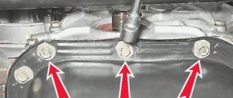
The ignition system needs maintenance, just like any other mechanism and component of the car. Since we are considering the GAZ 3307 truck, it would be appropriate to remember that such vehicles that work for an ATP (motor transport enterprise) include such concepts as TO-1 and TO-2. These are maintenance services that are carried out regularly after a certain mileage of the car. During the first maintenance, which takes place after 8,000 km on this car, we will need to tighten the nuts securing the low-voltage connector on the distributor and check the reliability of the fastening of the connecting wires.
But during the second maintenance you will have to do a little more work. It is carried out after 16,000 km. We will need to check the ignition distributor, in particular, look at the slider, check the distributor cover for cracks, wipe everything from dirt and dust with cotton paper. You will also need to lubricate the slider bushing with their pipettes; you need to add up to 5 drops of oil. In general, every 50 thousand km you need to check the stator and fill its ball bearing with Litol lubricant.
To prevent burnout of the distributor cap, you must always check the reliability of the armored wires; they must always be inserted all the way. It is also advisable to keep an eye on the ignition distributor switch so as not to start the engine if the cover is wet. It is important to keep all plastic parts under the hood of the GAZ 3307 clean, and this applies not only to the ignition system.
Appearance
In ignition systems with a variator, the reason is the low reliability of the latter. As for flirting, I can give you an example from life.
And just imagine this picture of a GAZ, let’s say after a year of production, there is, of course, ignition without an additional resistor. The distributor sensor has a housing, a cover, a roller, a sinusoidal voltage sensor, centrifugal and vacuum regulators, as well as an octane corrector.
Ordinary car wires with a central vein - a spider's web - are no better in this sense. Emergency vibrator fig.
The use of contact-transistor ignition systems makes it possible to: obtain higher output voltages by increasing the current in the primary winding and reduce the electrical load of the breaker contacts; increase the gap between the electrodes of the spark plugs to O.85...1.0 mm, which makes it possible to work on lean working mixtures and thereby reduce the toxicity of exhaust gases; facilitate starting and increase the reliability of engine operation at low and high speeds; increase the durability of the breaker contacts; reduce average operating fuel costs. Powerful ignition for little money Electrics As you know, few people are satisfied with the standard contact ignition of the Urals and Dnieper.
New blog posts
Replace the commutator Naturally, the spark of such coils is two times weaker than the “original” coil. Remove the plastic cover from the distributor sensor. battery; 9.
The distribution among the cylinders is in order. You can check it by connecting a light bulb to it, which will light up when the ignition is turned on. I had to turn it with my “handle” - there were no people willing to “carry” it. At the moment the contacts open, the disappearing magnetic field of the primary winding of the IT transformer penetrates the threads of the secondary winding of the IT and induces an EMF in them, which creates a reverse negative voltage at the emitter junction of the transistor, which contributes to the fastest turn-off of the transistor. In the complete absence of detonation, it is necessary to increase the ignition timing by turning the sensor-distributor housing clockwise.
ZIL 130, ZIL 131, GAZ 3307, GAZ 3102, GAZ 3110, GAZ 53, MAZ 500, T 25, T40, Izh Planet, Izh Jupiter
Replace the switch In the event of pulsed voltage increases, capacitor C2, when charged, prevents overvoltage of the transistor and the flow of large destructive current through it.
While a car ignition works with a spark plug gap of 0.0 mm, because this system has a higher breakdown voltage. Maintenance Check the tightness of the nuts of the low-voltage sensor-distributor connector and the fastening of the connecting wires. Ignition ZIL 4331 part 2
The most common malfunction
On GAZ 3307, the ignition coil most often malfunctions in the ignition system. As a preventive measure, you need to look at the reel cover more often, because it is plastic. It is necessary to clean it from dust and dirt, oil deposits, and check whether all the wires that are connected to it are securely attached.
Among the reasons for the malfunction of this ignition element are:
- Breakdown of insulating materials (both external and between the primary and secondary windings).
- Short circuit between certain turns.
- Violation of the integrity of the lid.
- Burnout due to unreliable fastening of the high-voltage wire.
In windings, violations most often occur due to the fact that the coil overheats. Before throwing away the coil of the GAZ 3307 car and putting a new one in its place, you need to check how securely all the wires are fastened there. Next, you need to check it using a stand. If it is in good order, then there should be high-quality sparking at the spark gap with a spark gap of 7 mm with a shaft rotation speed of 20 to 2300 rpm. If the coil does not fit into these requirements, you will have to throw it away and install a new one. And if a violation of the winding was visually noticed, then it needs to be changed immediately; checking at the stand is useless.
Verification methods
Given the external similarity of the electrical equipment, the automaker reasonably assumed the possibility of errors when servicing the car independently, the price of which was high. Therefore, I provided automatic protection of elements from accidental short circuits:
- The generator excitation winding circuit is protected using a protection relay, as well as a separating diode;
- While the engine and generator are running, the relay contacts are open;
- If a wire breaks or short circuits, the current flowing through the relay winding will increase;
- The opposing winding will create a magnetic field, the core will retract and open the relay contacts (see also the VAZ 2101 wiring diagram).
To check the serviceability of the protection you must:
- Turn off the engine;
- Turn on the ignition;
- Connect the voltage of the relay-regulator to ground;
- Alternately press the anchors RN and P3, closing their contacts.
If the relay is working properly, the voltmeter needle will move to the “0” mark. If this does not happen, the transistor is faulty and the relay regulator must be replaced.