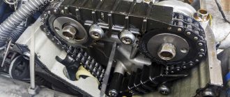
03/04/2022 44 408 Ignition system
Author: Ivan Baranov
The ZMZ 402 engine is one of the products of the Russian automotive industry, widely used in the automotive industry. These power units were equipped with certain models of Volga, UAZ, and Gazelle cars. To ensure normal engine operation, the machine must have the ignition set correctly. In this article we will tell you how to install a distributor on a 402 engine and what should be taken into account when performing the task.
[Hide]
How does the 402 ZMZ ignition system work?
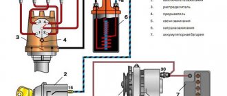
The contactless ignition system ZMZ-402 includes:
- ignition coil;
- breaker-distributor (distributor);
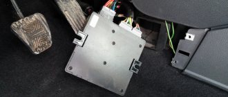
- switch;
- high-voltage and low-voltage wires;
- spark plug.
Using the battery's energy, the coil generates an electrical impulse. It works on the principle of a transformer. The commutator amplifies the distributor signals and controls the currents in the primary circuit of the coil.
The distributor is called differently, including a sensor-distributor (it includes a magnetoelectric sensor and a pulse distributor).
The distributor shaft is rigidly connected to the drive shaft, which is driven by the oil pump gear. A centrifugal ignition timing regulator (IAC) is installed on the shaft. As the crankshaft speed increases, the weights diverge and provide a larger advance angle. When the rotation speed decreases, the spark is supplied later.
However, this adjustment is not enough. The vacuum regulator is responsible for adjusting the OZ according to the load on the engine:
- When you press the gas pedal, the throttle valve opens, and the resulting vacuum acts on the diaphragm.
- The diaphragm moves a mechanical drive, which changes the SOP.
- With the new throttle position, the vacuum stabilizes. By this time, the correct angle is already maintained by the centrifugal regulator.
Together, both mechanisms correct the SOP in dynamics and in steady state. The initial, static position of the regulator body is set during installation.
Adjustment is carried out by turning the distributor body in the mounting hole. The position is fixed with a bolt passing through the scale plate. The scale division value is 2° of the PCV angle (crankshaft rotation).
A slider is installed on the top of the distributor shaft, which, rotating, in turn supplies voltage to the contacts in the distributor cover (they are routed to the high-voltage wires going to the spark plugs).
When installing wires, it is important to connect them correctly. The operating order of the cylinders is 1-2-4-3, on the ZMZ-402 it is different from the usual 1-3-4-2 (for example, on a Zhiguli).
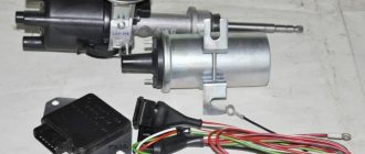
Before installing the distributor sensor on the vehicle, make sure it is in good working order. Carry out at least an external inspection, or better yet, measure important parameters:
- resistor resistance 5–8 kOhm;
- stator winding resistance 0.45–0.50 kOhm.
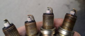
Note for beginners: If you have already adjusted timing valves, be aware that these spark plug probes will not work. Checking the spark plug gap is carried out using round feeler gauges.
- the gap between the spark plug electrodes is 0.8 mm;
- spark plug resistance is 4–7 kOhm.
A crack in the cover causes interruptions in the operation of the device. Without noticing it, you can adjust the SOP for a long time and uselessly.
What you need to know
In order to properly configure and adjust the ignition of the ZMZ 402, you need to know some nuances about the operation of the power unit. Such motors have a non-contact distributor installed, supplemented by a control signal generator and mounted advance regulators - vacuum and centrifugal (video author - smotri Vidik).
The distributor is designed to perform certain functions:
For the correct distribution of impulses, a slider mounted on the mechanism pulley is used. The slider is equipped with a resistor and is designed to suppress interference. The switching device performs the function of opening the ignition coil winding circuit, converting control signals from the regulator into short-circuit current signals.
To correctly install the ignition on a 402 engine, it is necessary to take into account the system characteristics presented below:
Installing the ignition on a 402 engine
You can correctly install the distributor on the 402 ZMZ engine with your own hands. It should be placed in such a position that the spark occurs at the end of the compression stroke, approximately 5 degrees of crankshaft rotation before top dead center. The ignition timing is set according to the first cylinder.
A distributor drive equipped with a helical gear is inserted into the cylinder block, and the breaker-distributor itself is inserted into it. Therefore, you need to consider two installation options:
- No drive. When the drive is inserted into the block, there is no need to install the crankshaft pulley according to the marks. At the end of the distributor shaft there are two protrusions that are offset from the center. Inside the drive, on the shaft there are slots corresponding to them. Thus, the distributor shaft is installed in only one position. The unit is located at the rear of the power unit. During installation, the distributor housing must be turned by the vacuum regulator towards the first cylinder.
- Complete with drive . When installing the distributor-distributor and its drive together, the position of the engine mechanisms must be correctly set.
Malfunctions and their elimination
Like any technical product, the Gazelle-Business motor is susceptible to breakdowns. Sometimes it needs repairs for various reasons. The most common problems that arise are:
- The motor does not start. Most likely there is no fuel supply to the injectors. It is necessary to use the appropriate fuel, rinse and clean the fuel intake.
- The tightness of the pipeline between the tank and the electric pump is broken. The connection points should be checked and the tightness restored.
- There are problems with the control electronics. It is necessary to replace faulty parts of the unit.
- Poor power delivery indicates problems in the electronic control system. After testing, it is necessary to replace the unusable element.
- The fine filter is clogged. In this case, the filter element must be replaced.
- Air appears in the fuel block. It is necessary to check and ensure the tightness of the system.
- If problems are detected in the fuel pump, the faulty injectors should be replaced.
How to set top dead center
During the working cycle, the piston passes the TDC position twice - the end of compression and the end of exhaust. We need the compression end. On a 402 motor, you can determine it in three ways:
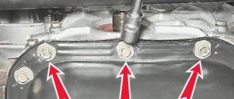
- If the valve cover is removed . This position should correspond to closed valves (both rocker arms are with gaps and approximately in the same position). In this case, the KV pulley is installed on the middle mark, opposite the fixed pointer - it corresponds to the ignition timing angle.
- If you remove the distributor with the drive , and then you have to mount it back, then with the distributor cover removed, manually rotate the crankshaft until the slider points to the contact of the first cylinder, and the familiar mark on the CV pulley is opposite the pointer. Now the distributor sensor can be removed. During repairs, the HF cannot be rotated, since it must be installed in the same position.
- When the distributor drive has already been removed , the crankshaft is in an arbitrary position, and there is no reason to remove the valve cover, you need to do the following: unscrew the spark plug of the first cylinder, close the spark plug hole with your finger and crank the engine until compression pressure is felt. All that remains is to bring the HF to the mark. The spark plug hole can be plugged with a homemade plug (chop), it is made from polyethylene, paper, rubber, or other available materials. When the piston begins to compress and the device flies up with a characteristic sound, also bring the KV pulley to the mark.
Now you can insert the distributor:
- Remove the distributor cover and install its shaft correctly, orienting the slider to the contact of the first cylinder. However, if you place the distributor in this position, the slider will turn counterclockwise. It's all about the helical gear: when installed, the inclined tooth, sliding in engagement, turns the shaft, so the slider must be installed by turning it about 45° and checking its position.
- Repeat the installation if a tooth is lost.
- Connect the wire from the pulse generator to the switch.
- Set the scale to zero.
- Having loosened the bolt securing the octane corrector plates, you need to align the red mark of the rotor with the stator mark. Lock the bolt in this position.
- Close the distributor cover (it has a protrusion that aligns with the distributor slot for installation in a single position).
- Connect the vacuum regulator hose.
- Install the first cylinder wire and the center wire.
- Connect and check the correct connection of the high-voltage wires of the remaining cylinders, taking into account the operating order 1-2-4-3.
After any assembly work, it is advisable to crank the motor manually two turns KV . If the crankshaft turns without complaints, you can turn on the ignition.
If the engine does not start, or maybe even “shoots” at the carburetor, then either the distributor is installed with an error of 180° and the spark jumps at the end of the exhaust, or the wires are mixed up. You should swap them or reinstall the sensor-distributor itself.
Finally, the car started up, warmed up (better while driving), and now you can finally adjust the ignition timing.
GAZ Club community
It’s almost worth using a strobe light on the VOLGA. The MH is installed at the middle mark (for the 92nd, or in the center between 3 and 2 for the 80th). If there is a BSZ, you need to combine the mark on the magnet with the arrow on the sensor coil body (at the same time, turn the magnet to the right until it stops). Before installing the MZ, set the middle mark of the octane corrector opposite the arrow of the washer under the fastening bolt, make the adjustment itself by releasing the bolt from the BOTTOM REAR of the pump body (if there is not enough adjustment space with the bottom bolt, use the octane corrector bolt). The final adjustment of the OZ should be carried out on the road (from a speed of 40 km/h, sharply press the gas to the floor. A short-term DETONATION should appear. The knocking can occur up to 65-70 km/h). Fortune.
Dude who helps from time to time Messages: 532 Registered: 05 Sep 2013, 16:54 From: Ryazan Contact information:
There is a factory annotation that is unclear.
This is a table for the 402nd motor.
1. Turn off the vacuum pump using a straw.
2. Specifically check -
600 rpm - 5 g advance, this is the middle or second mark on the crankshaft pulley. We look with a strobe light. 1st mark - TDC, 3rd - 12 deg.
Then we put the assistant in the cab, he uses the gas pedal to increase the speed to approximately 850. Looking at the table, it should be 10 g. Using a stroboscope, look at the marks somewhere between the 2nd and third marks of the crankshaft pulley.
Then the assistant increases the engine speed to approximately 1250. The stroboscope should show 12-14 degrees, i.e. 3rd mark on the c/v pulley.
Further 1750 rpm = 15-18 degrees, from the third mark you need to add a distance with a marker equal to the length between the first and 2nd marks, i.e. 125=17 g advance.
In fact, there is another method, I'll look for it at the moment.
Last edited by Dude on Sep 14, 2013, 01:26 pm, edited 1 time in total.
Dude who helps from time to time Messages: 532 Registered: 05 Sep 2013, 16:54 From: Ryazan Contact information:
It was like this: it jerks at 1500 rpm. on any transmission. And what’s most interesting is that it’s on gas. that on gasoline. What I did in the fight for stability: I replaced the spark plugs. I changed the wires, the trampler, the crosspieces, the rims and the wheels, but the problem was as it was
This is an incorrectly installed ignition and an unconfigured distributor. 99.9%.
It is easy to check - the distributor is 1-2 divisions in the later direction - counterclockwise. And at 1500 rpm we check whether the twitching is gone or not. How it drives in the rest of the spectrum is not yet interesting, so far only 1500 rpm.
If this is a problem, we begin to configure the distributor.
We turn on the second speed, try to move off at idle with 2nd or with a small throttle boost. We remember how the car started moving, sorry, here we can only measure it with a pomeranian, I don’t know the best method. Next, we first turn the trailer by 1 division clockwise, then counterclockwise. The point of all these actions is to find the position of the distributor for the best start at XX or min rpm, the best torque, and light pressure on the accelerator.
Next we set up a small distributor spring. This will be a spectrum from approximately idle to 1500 rpm. Everything is the same as we set up XX. Distributor one division clockwise, check, one division counterclockwise, check. Determines the best position of the brake for accelerating the XX-1500. If the positions of the distributor for the spectrum of a small spring and the spectrum of XX coincide, then great; if they do not coincide, then we bend or weaken the stand of the small spring in the distributor. There is a special window in the distributor for this. Just figure out in which case where to bend it. And similarly we adjust the huge spring of the distributor for the best acceleration and the highest traction and low pressure on the gas pedal. A large spring comes into operation here and there after 1500-2000 rpm.
Setting the ignition timing
It is necessary to adjust the OZ so that the engine produces full power, operates economically, has the proper dynamics and does not detonate. To organize an efficient internal combustion engine operating process, they try to burn fuel in a minimum volume - when the piston is positioned near TDC. This means that when it approaches the top position, the mixture should already be burning. To do this, the spark is applied before TDC.
Early ignition
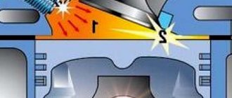
If you apply a spark too early, then when you sharply press the gas pedal we will hear the so-called “ringing of fingers”, they also say: “fingers crunch”. In reality, it is not a pin, but a piston that hits the cylinder liner with a throne (a skirt, as they said in the old days). This happens due to detonation - explosive combustion of fuel, the causes of which are low-octane gasoline and early ignition .
Detonation in the engine combustion chamber: 1 - normal combustion zone, 2 - detonation zone.
Some ignition distributors were equipped with octane correctors. The device made it possible to adjust the dispenser without unscrewing the distributor fasteners by rotating the adjustment wheel.
When detonation occurs, the fuel burns inefficiently and causes damage to the engine:
- The enormous energy of the explosion hits the piston and does not so much move it down as it tends to destroy it.
- The maximum cycle temperature also increases.
- Detonation leads to failure of the cylinder-piston group - the rings and inter-ring partitions of the pistons break.
Early ignited fuel resists the piston while it is still moving upward. This leads to excessive fuel consumption and strained engine operation.
With very early ignition, the piston is so braked during engine startup that the crankshaft is almost thrown back. The starter has difficulty cranking the engine, and the battery consumes a lot of energy.
Late ignition
If the spark is applied too late, the combustion process will shift to the expansion line - the bulk of the fuel will burn at a rapidly increasing volume. The gases press on the piston as if in pursuit, which is ineffective. The temperature of the exhaust gases increases because the mixture does not have time to burn out; sometimes the process ends in the muffler. Because of this, a lot of thermal energy is lost to the cooling system. The car consumes a lot of excess fuel and accelerates sluggishly.
Work principles.
Using the signal from the crankshaft position sensor, the control unit calculates the rotation speed, and the amount of cyclic air filling of each of the four engine cylinders is determined by measuring the absolute pressure. The ignition timing angle, which depends on the cyclic filling and rotation speed, and corresponding to the engine operating frequency, is stored in the unit’s memory device. These angular values have an additional adjustment depending on the coolant temperature. Providing good traction properties under these conditions is achieved by increasing the angular values of the ignition timing in a cold engine. Also, if a detonation fire is detected due to certain factors, such as changes in environmental conditions or the use of low-octane fuel, the control unit will adjust the SOP. If the absolute pressure or ambient temperature sensors are damaged, the control unit activates emergency programs and turns on diagnostic lamps. Reduced power, deterioration of dynamic properties, increased fuel consumption - all these are the results of operating a car engine with these malfunctions. In addition, in addition to ignition control, the functions of the unit include control of the economizer solenoid valve for forced idle speed, which, when the vehicle is braking by the engine, ensures that the fuel supply is turned off. The crankshaft rotation value to turn off the fuel supply is 1860 rpm, and to resume the supply - 1560 rpm.
Setting the ignition timing
The parameter is configured in two ways:
- By strobe light. This device allows you to check the correct installation of the OZ on the car. By connecting it, you can easily set the value prescribed by the manufacturer. However, it is designed for ideal gasoline and a standard engine, which is not always justified in practice.
- In move. Experienced mechanics recommend the following setup procedure: warm up the car and depress the gas pedal at a speed of 50–60 km/h. If the sound of detonation is not heard, it means that the ignition is late; with prolonged detonation, it means that the ignition is early. It is necessary to ensure that the “fingers crunch” for a short time (1–3 s) - this will be the optimal ignition timing.
Preparatory process
Before you begin adjustment work with your own hands, you need to prepare the necessary tools and consumables, which include:
- set of measurement probes;
- a set of wrenches (socket or ring);
- new valve cover gasket;
- crankshaft ratchet key;
- spark plug wrench Needed to remove spark plugs;
- Phillips and flathead screwdrivers;
- clean rags.
Upon completion of preparation, when all the required tools are prepared, you can proceed directly to the adjustment work.
Injection motor
In terms of technical characteristics and components, an engine with an injection power system is not very different from the carburetor analogue of the 405 model.
With proper operation, this unit is no less reliable and practical than with a carburetor, and in addition has its own advantages:
- Stable idle speed.
- Low level of harmful emissions into the atmosphere.
- The efficiency of the ZMZ-406 injector is much higher than its analogue with a carburetor, since the fuel mixture is supplied in a timely manner and in the right quantity. Accordingly, fuel savings are obvious.
- Improved fuel economy.
- Does not require prolonged engine warm-up in winter.
The only disadvantage of an injection engine is the high cost of repair and maintenance of the system.
Technical characteristics of the Volga
The engine is an in-line four, an eight-valve mechanism. Many parts of the gas 24 engine were made of aluminum-zinc alloy: the internal combustion engine block, the cylinder head, the intake manifold. The body was produced in two versions - sedan and station wagon.
The volume of the fuel tank was 55 liters, since the consumption was relatively large, the tank had to be not small. It was located under the bottom of the trunk. Another feature of the tank was two sensors for measuring the amount of fuel. Manually, by placing the car on a flat surface, you could unscrew the plate with divisions from the tank, which showed the remaining fuel on the instrument panel.
The latter often failed and car owners often used a manual one. Fuel consumption ranged from 10-13 liters per 100 km. Transmission - 4-speed with synchronizers for all gears, single disc clutch, dry with hydraulic drive. Chassis: front independent, multi-link, pivot type. Rear: dependent, spring. Shock absorbers are telescopic, double-sided. Braking system: drum, installed on all 4 wheels. Parking brake with rear wheel drive.
Source
Features of fuel ignition
Before installing and correctly setting the ignition order on the 402 engine, it is important to understand the design features of the distributor. This engine was equipped with an electric flow distributor without traditional metal contacts. The innovation is that the complex process is controlled together with the generator by a vacuum advance regulator.
The distributor sets the order in which the spark appears and the sequence in which the fuel is ignited in the cylinders. A mechanical slider helps to correctly “catch” the moments of the spark discharge. It is mounted directly on the pulley. Has a resistor to help mix noise. The switching device disconnects the circuit in the first coil. Subsequently, it converts electrical impulses emanating from the node into an intermittent short-circuit current.
Brief history of the car
The Volga was the dream of every Soviet family, but the average resident could not afford it. This car became the next generation of the GAZ-21 brand. Many developments and prototypes were made from 1960 to 1967.
Many engine options were considered, including a V-8 engine for gas 24, but in the end, only two options remained: an in-line four-cylinder with V = 2.5 liters and a 4-speed manual transmission and a 5.5 with a 3-automatic transmission. The body design was based on the American school and the car became similar to its American counterparts, such as: Plimutee Volare, Dodge Dart, Chevrolet Nova.
This is what the gearbox looks like for Volga GAZ 24
Over time, this model became widespread in taxi companies, medical institutions, police, and the famous “Black Volga” was used by officials and law enforcement services.
Instructions for connecting short circuit
The ZMZ 405, 406 and 409 engines use two short circuits - one of them works with cylinders 1 and 4, and the second with cylinders 2 and 3. The first of them is located closer to the intake manifold, and the second is located next to the exhaust manifold. To make the connection correctly, low voltage wires should be connected in pairs - those used for the first coil (cylinders 1-4) will be shorter in length. Since the short circuits themselves are not polar, it does not matter which contact the cable will be connected to; it also does not play a role within the pair to which cylinder the wire will be connected (the author of the video is the SpawnyXC90 channel).